US4553548A - Interrogator for muscle stimulator - Google Patents
Interrogator for muscle stimulator Download PDFInfo
- Publication number
- US4553548A US4553548A US06/524,851 US52485183A US4553548A US 4553548 A US4553548 A US 4553548A US 52485183 A US52485183 A US 52485183A US 4553548 A US4553548 A US 4553548A
- Authority
- US
- United States
- Prior art keywords
- counter
- signal
- level
- interrogator
- compliance
- Prior art date
- Legal status (The legal status is an assumption and is not a legal conclusion. Google has not performed a legal analysis and makes no representation as to the accuracy of the status listed.)
- Expired - Fee Related
Links
Images


Classifications
-
- A—HUMAN NECESSITIES
- A61—MEDICAL OR VETERINARY SCIENCE; HYGIENE
- A61N—ELECTROTHERAPY; MAGNETOTHERAPY; RADIATION THERAPY; ULTRASOUND THERAPY
- A61N1/00—Electrotherapy; Circuits therefor
- A61N1/02—Details
- A61N1/08—Arrangements or circuits for monitoring, protecting, controlling or indicating
-
- A—HUMAN NECESSITIES
- A61—MEDICAL OR VETERINARY SCIENCE; HYGIENE
- A61N—ELECTROTHERAPY; MAGNETOTHERAPY; RADIATION THERAPY; ULTRASOUND THERAPY
- A61N1/00—Electrotherapy; Circuits therefor
- A61N1/18—Applying electric currents by contact electrodes
- A61N1/32—Applying electric currents by contact electrodes alternating or intermittent currents
- A61N1/36—Applying electric currents by contact electrodes alternating or intermittent currents for stimulation
- A61N1/3604—Applying electric currents by contact electrodes alternating or intermittent currents for stimulation for correcting spinal deformities, e.g. scoliosis
Definitions
- the invention pertains generally to a pulse generation apparatus used for muscle stimulation and is more particularly directed to an interrogator for such muscle stimulators which are used in the treatment of Scoliosis and other related spinal deformities.
- the reference includes a means for sensing compliance with a therapeutic level of the treatment described therein.
- the compliance sensing means is implemented as a comparator generating a first output level if the intensity level setting of the stimulation is greater than a compliance level and a second output level if the intensity level is less than the compliance level.
- the compliance signal is thereafter used to visually indicate to the patient when the treatment level is in excess of the compliance level.
- the indication is useful in setting the intensity level of the treatment device such that the level can be adjusted upwardly as the tolerance level increases to the therapeutic level without overtreatment and unnecessary discomfort.
- the compliance indication is additionally useful in allowing the patient to record the period of time during which a therapeutic level of stimulation is applied.
- the clinician who is supervising a treatment regime has little way of confirming how concientiously the patient is adhering to the treatment schedule set out. Other than the times during an office visit, the clinician has little control over the course of the treatments.
- the clinician must interrpret the data given him by the patient as to compliance with the treatment regime and compare that with the actual progress being made. From the comparison he will attempt to make course corrections that will increase the progress of treatment and reduce the overall duration of the regime.
- the invention overcomes these problems and provides a means for accurately accummulating the amount of time that the intensity level of a treatment device, such as a muscle stimulator, is in excess of a therapeutic level.
- the invention additionally provides means for interrogating the accumulator, storing, and displaying the accumulated total time.
- a clinician using a muscle stimulator in the treatment of scoliosis or a related disease can make significantly better course corrections than one that has questionable data. Further, if a clinician has the patient keep substantially accurate records of a treatment regime, the data supplied by the invention can be used as a cross check to ensure treatment compliance.
- the invention comprises a counter contained internally within a muscle stimulator or treatment device to store counts of a clock waveform having a periodic rate.
- the clock waveform is enabled to the counter causing a count accumulation during the presence of a compliance signal indicating that the intensity level of the treatment device is in excess of a therapeutic level.
- the clock waveform is of a constant frequency and therefore causes a time count accumulation in units of the waveform period.
- the invention further comprises a means and method for interrogating the time accumulation in the internal counter.
- the interrogator comprises a means for clocking the internal counter for a full cycle of its maximum count i.e. from zero to overflow, means for receiving an overflow signal from the internal counter, and means for counting from the overflow to the end of a cycle. In this manner the counting means and the internal counter will both initiate counting at the same count (zero), and accumulate counts to the same count (that which was previously stored in the internal counter). A duplication of the count stored in the internal counter is thereby transferred to the counting means.
- the invention in response to a reset signal, includes means to terminate the clocking cycle upon the receipt of the overflow signal. This provides a means for clearing the internal counter such that a new treatment record can be started.
- FIG. 1 is a detailed block diagram of a muscle stimulator used for the treatment of Scoliosis and other related spinal deformities;
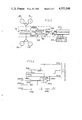
- FIG. 2 is a detailed block diagram of a muscle stimulator system including the muscle stimulator illustrated in FIG. 1, an elapsed time counter for accumulating the time of treatment at a therapeutic level, and an interrogator for reading, storing, and displaying the accumulation;
- FIG. 4 is a detailed electrical schematic diagram of the interrogator illustrated in FIG. 2;
- FIGS. 5A-J are pictorial representations of waveforms at various places in the circuitry illustrated in detail in FIGS. 3 and 4;
- FIG. 6 is a pictorial representation of the muscle locations used in a course of treatment with the muscle stimulator illustrated in FIG. 1;
- FIG. 7 is a flow diagram of the necessary steps for the treatment of scoliosis or other spinal deformities using the muscle stimulator illustrated in FIG. 1.
- FIG. 1 there is shown a detailed block diagram of a dual channel muscle stimulator or therapy device 10 which can advantageously be used with the invention.
- the muscle stimulator is contemplated as a portable hand held device which can be conveniently used in the home setting of the patient.
- the device is usually battery powered to provide greater flexibility in its use.
- the packaging and power supply of the device have not been illustrated since it is not relevant to a description of the invention, but it should be noted that the circuitry described will be compatible with this context.
- the muscle stimulator 10 develops burst of pulses having "on” and “off” periods from the outputs of two channel driver circuits 18, 36.
- the channel 1 driver circuit 36 for example generates pulses to terminals 42, 44 of an input jack into which a plug 46 connected to the lead terminals 27 of an electrode pair 48, 50 is inserted.
- the electrodes 48, 50 are positioned on a patient in a manner which will be more fully described with reference to the procedure for the treatment of deformity.
- the channel 2 driver circuit 18 is connected to electrodes 32, 34 via input jack terminals 24, 26; plug 28, and lead terminals 30.
- Each channel driver transforms a logic level pulse train or timing signal generated from timing generator 12 into a higher level output pulse train of a predetermined pulse width and with a constant current level.
- the channel 1 driver circuit 36 transforms the pulse train P1, P1 into a higher level waveshape and the channel 2 driver circuit 18 transforms the pulse train P2, P2 into a higher level waveshape.
- the step up in power is accomplished by providing each channel driver circuit 18, 36 with a high DC potential Vh. Basically, the high potential Vh is applied to the electrodes during the presence of a timing pulse and the current of each resulting high level pulse controlled to a predetermined value.
- the high DC potential Vh is obtained from a DC-DC converter 16 which transforms battery potential into a supply potential of approximat 180 V DC at its peak.
- the converter 16 utilizes a 3 KHZ signal input from the timing generator 12 in the voltage step up process.
- the wave shape of the attenuated high voltage potential Vh is generated as always greater than or equal to the waveshape of an input signal RAMP generated from a ramp generator 14.
- the DC-DC converter 16 thus acts as a means of amplifying or stepping up the power and voltage of the output of the ramp generator 14.
- the trapezoidal waveform period is based on the period of a square wave master clock signal MCLK input to the ramp generator 14 from the timing generator 12.
- the trapezoid is generated by linearly ramping from a zero level to a base level at one transition of the MCLK signal and then by linearly ramping from the base level to a zero level at the other transition of the master clock signal MCLK.
- each driver circuit for example channel 1 circuit 36, is a compliance detector 38 and a fault detector 40.
- the compliance circuit 38 receives the signal RAMP and a signal ILS which is an indication of the current intensity level of the driver circuit 36.
- the RAMP signal is used to generate a compliance current level which is set during a visit to the clinician. These levels are compared and a compliance signal COMP1 is generated when the intensity level of the pulses is greater than the level set by the clinician.
- a compliance detector 20 is connected and operates similarly to the compliance detector 38 to generate the signal COMP2 for channel 2 compliance.
- the compliance signals COMP1, COMP2 are received by a compliance indicator circuit 54 which is adapted to visually indicate whether compliance or noncompliance is taking place with respect to the intensity setting for each channel.
- the signal MCLK is used by the compliance indicator 54 to differentiate between the two separate channels and the 1.5 HZ signal used to drive an indicating device.
- the muscle stimulator system according to the invention is set out more clearly in block diagram form in FIG. 2.
- the dual channel stimulator 10 previously described in FIG. 1 has contained within the same physical case 62 an elapsed time counter 60.
- the elapsed time counter receives the compliance signals COMP1, COMP2, and the master clock signal MCLK.
- the elapsed time counter will be incremented at the rate of the master clock signal MCLK. Because this signal has a predetermined frequency the count in the elapsed time counter 60 will be representative of the time the compliance signal are present.
- the time units of the count are equivalent to the period of the master clock signal MCLK.
- the elapsed time counter 60 can be read by an interrogator 66 connected remotely via a transmission line 64.
- the interrogator performs the interrogation by transmitting an interrogate signal INTS to the elapsed time counter 60 via the trnasmission line 64.
- the elapsed time counter is adapted to reply via the transmission line 64 with an overflow signal OFS.
- the communication interface between the interrogater and the elapsed time counter additionally includes a common connection to the negative battery voltage -V for a reference.
- FIG. 3 Detailed circuitry comprising the elapsed time counter circuit 60 is more fully illustrated in FIG. 3 where a counter 382 is used to record cycles of the treatment device which are in excess of the compliance level.
- the counter 382 is incremented by a driver, NOR gate 390, which has its output connected to the clock input IN2 of the counter via resistors 384, and 388.
- One input of the NOR gate 390 receives the channel 1 compliance signal COMP1 via diode 392 and the other diode 394.
- the cathodes of the diodes 392, 394 are joined to provide a wired AND function.
- the other input of gate 390 is connected to the junction of the serial connection of a capacitor 396 and a resistor 398 connected between the master clock signal MCLK and positive battery voltage +V.
- both of the compliance signal COMP1, COMP2 provide an enabling signal (low logic level) to the NOR gate 390 indicating that compliance with a therapeutic level is taking place on both channels, then a pulse generated by the differentiator formed by capacitor 396 and resistor 398 passes through the gate 390 and clocks the counter 382. If only one channel is being used then that is the only compliance signal necessary to enable the counter 382. If enough counts have accumulated to cause the counter 382 to overflow, as sensed by a high logic level from the 2 20 output, then this bit is used as an overflow bit signal OFS for transmission to the interrogator 66. A resistor 386 feeds the OFS signal back to the input of the gate 390 such that the gate is disabled in the event of an overflow.
- the counter 382 is adapted to have its contents read by the external interrogator circuit 66 by having the interrogator signal INTS connected to its clock input IN2.
- the interrogator includes a four digit display counter 418 which drives four seven segment displays 420, 424, 426 and 434 connected in parallel with the inputs S1-S7 of the counter.
- Each display 420, 424, 426, 434 is enabled by a separate NPN transistor 436, 438, 444, 442 respectively, by having the collector of the transistor connected to common cathode input EN of the display.
- the emitters of the transistors 436, 438, 444, 442 are commonly connected to the negative battery voltage -V via the collector emitter path of a transistor 450 while their base terminals receives enabling signals directly from selector outputs A, B, C, D respectively of the counter 418.
- Th four digits of an internal counter are placed output lines S1-S7 sequentially in the code of the seven segment displays. Each digit is simultaneously accompanied by an enabling output signal from one of the outputs A-D.
- the activation and transfer of the digits is at a frequency such that the display appears as a solid readout.
- the four digit contents of the display driver is refreshed by the internal counter 418 whenever the load enable input LE is activated and remains displayed until the next sequence.
- the internal counter of the display counter 418 is incremented by a signal applied to the clock input C of the display counter 418 and is reset by a signal applied to the reset input R of the display counter.
- the display counter 418 is clocked by the 2 9 output of a divider counter 412.
- the divider counter 412 has its 2 3 , 2 5 , 2 7 , and 2 9 outputs decoded by an 410 whose output drives the D input of flip flop 414.
- the Q output of the flip-flop 414 is connected to the reset input R of counter 412.
- the clock input C of the flip flop 414 and the divider counter 412 are commonly connected to a clock line carrying the interrogator clock signal ICLK.
- the divider counter is incremented by the signal ICLK and generates its clock signal to the counter 418 every predetermined number of increments.
- the number of counts in the divider counter 412 is decoded by the AND gate 410 which provides a high level output to the D input of flip flop 414 when that number is reached. Because of the high logic level provided to the D input, the next ICLK pulse to the flip-flop 414 sets the Q output thereby resetting the divider counter 412.
- the divider counter thereby divides the frequency of the ICLK signal by a predetermined constant. In the present embodiment this constant is 534 which is a conversion factor to changes the ICLK pulses representing counts of the MCLK signal to hours.
- a cycle counter 416 is additionally provided to determine when one full cycle of interrogation has been accomplished.
- the clock input C of the cycle counter 416 is driven by the signal ICLK and complete signal COMP is generated from its 2 22 output .
- the cycle counter is twice the length of the elapsed time counter in the therapeutic device. A complete interrogation cycle is therefore a clocking from a zero condition to an overflow of the cycle counter corresponding to an analogous complete cycle for the elapsed time counter.
- the cycle complete signal COMP is applied to the D input of an interrogate flip flop 494.
- the clock input C of the flip flop 494 receives the signal ICLK and the reset input R of the flip flop 494 receives an interrogate command INTC in the form of a pulse from a differentiator circuit and an interrogate button 498.
- the interrogate button 498 connects positive battery voltage +V through terminals 496, 500 to a capacitor 504.
- the capacitor 504 is connected to the negative battery voltage -V through a resistor 502 and at the other terminal is connected to negative battery voltage -V through a resistor 506.
- the rising edge of the positive voltage is differentiated by the resistor-capacitor combination, 502, 504 and 506 to become a positive pulse interrogate command INTC.
- the interrogate command INTC is additionally applied to the clock input C of a reset flip flop 490 and to the reset input R of an overflow flip flop 480.
- the reset flip flop 490 of an overflow its D input the reset signal RST.
- the signal RST is generated by a push button 482 connecting positive battery voltage +V via terminals 482, 484 to one terminal of a resistor 486 whose other terminal is connected to negative battery voltage -V.
- the Q output of the reset flip flop is connected to one input of AND gate 492 whose other input is the Q output of the overflow flip flop 480. Therefore, if the reset button is depressed and held, and subsequently an interrogate command is given, then the reset flip flop 490 is set. If the reset flip flop 490 is set at the time the overflow signal is received the cycle is terminated. The internal counter of the therapy device is thereby cleared to a zero count.
- the overflow flip flop 480 records the occurance of an overflow of the elapsed time counter 60 by having its clock input connected to the OFS signal via a NPN buffer transistor 478 and its D input connected to positive battery voltage +V.
- the base of the transistor 478 is connected to the external transmission line via resistor 476 and its collector-emitter path connected between the clock input C of the flip flop 480 and negative battery voltage -V.
- a pullup resistor 474 is also provided between the collector terminal of the transistor 478 the positive battery voltage +V.
- An initial power on reset is applied to the set inputs S of the overflow flip flop 480 and the reset flip flop 490 via a reset circuit comprising a capacitor 404, a resistor 400, and an on/off switch 402.
- the capacitor 404 is connected between the positive battery voltage +V and one terminal of a resistor 400 whose other terminal is connected to the negative battery voltage -V.
- the on/off switch 402 shorts the capacitor 404 when in the on position.
- the set terminals S upon power up therefore, initially have positive battery voltage +V applied to them causing a predetermined state transition.
- the voltage on the capacitor 404 charges lowering the voltage at the junction of the capacitor 404 and resistor 400 thereby removing the reset.
- the initial power on reset is additionally applied through diode 406 to the set input S of flip flop 414 and the reset input R of the display counter 418.
- a reset signal from the output Q of the overflow flip flop 480 via resistor 408.
- the interrogator clock signal ICLK is generated by an oscillator 508 at a much higher frequency than the master clock signal used for incrementing the elapsed time counter. In the preferred embodiment the interrogator clock frequency is 2 MHZ.
- the interrogator clock signal ICLK is transmitted to the clock inputs C of the cycle counter 416, the divider counter 412, the interrogate flip flop 494, and the decoder flip flop 414 via the output of a NOR gate 510.
- a companion NOR gate 512 transmits the interrogator clock signal ICLK to a transmission line driver circuit via its output.
- the NOR gates 510, 512 are each enabled and disabled by the logic level signal CEND which is generated as by the Q output of the interrogate flip flop 494 which and is indicative of the start and end of a cycle.
- the line driver circuit comprises a PNP transistor 520 connected in a inverter configuration in order to drive the transmission line between the interrogator and the elapsed time counter of the therapy device.
- the ICLK signal is delivered to the base of the transistor 520 via the capacitive coupling of a capacitor 514 and a resistor 516 from the output of NOR gate 512.
- a diode 518 is poled between the base and collector terminal of the transistor 520 to provide drive only for positive pulse transitions.
- a load resistor 524 is coupled to the collector terminal of the transistor to generate a driving voltage.
- the voltage generated between the negative battery voltage -V and the output at the collector terminal is trasmitted via the parallel connection of a capacitor 526 and a resistor 528 to the transmission line.
- the output of the line driver circuit at the transmission line connection is termed the interrogate signal INTS and is a buffered clock to the internal elapsed time of the muscle stimulator.
- a low battery voltage protection circuit is used to alert personel utilizing the interrogator when battery voltage begins to drop below a certain point and thereafter disables the display if the voltage continues to drop. Since the display draws the largest amount of power from the batteries this feature provides protection from completely discharging the batteries and also provides a protection feature for the count stored in the elapsed time counter 60.
- the warning from the low battery protection circuit is provided by the output of a comparator 464. The output is connected to positive battery voltage +V through resistor 466 and additionally to the input for the decimal point 422 of display 420. When the decimal point is activated the battery voltage is safe and comparator 464 will be nonconducting.
- the comparator 464 when the battery voltage +V drops below a predetermined level the comparator 464 will become conducting thereby sinking current from resistor 466 and turning off the decimal point indication.
- the reference voltage for this operation is provided at the junction of the serial connection of a resistor 460 and a band gap reference, Zener diode 462, connected between the battery rail +V, -V. This reference voltage is input to the inverting input of the comparator 464 which has a portion of the battery voltage +V input to its noninverting input.
- the portion of the actual battery voltage is developed at the junction of a set of divider resistors 468, 472 connected in series with a resistor 452.
- a capacitor 470 is provided in parallel connection with resistor 472 to provide filtering.
- a comparator 458 disables the display by comparing the reference voltage developed at the junction of the Zener 462 and resistor 460 with the voltage developed at the junction of resistor 452 and resistor 468.
- a capacitor 456 is connected in parallel across resistors 468, 472 to provide filtering for this voltage.
- the comparator 458 will sink current away from the base of transistor 450. This action will cause a high impedance path between the transistors 436, 438, 444, and 442 which enable the displays and the neagative battery voltage -V thereby disabling the displays. Since the voltage at the junction of resistors 468, 452 is greater than the voltage at the junction of resistors 468, 472, the comparator 458 becomes conducting after the comparator 464 becomes conducting due to the battery voltage dropping.
- the clinician connects the interrogator to the therapy device via the transmission line whereby the signal INTS can be transmitted to the elapsed time counter of the device and the siqnal OFS can be received by the interrogator circuit from the device.
- the power is then turned on which generates the power on reset to set flip flops 480, 490 which thereafter sets flip flop 492 via AND gate 494.
- the power on reset sets flip flop 414 to produce a clearing of counter 412 directly resets counter 418.
- the setting of flip flop 494 generates a high level logic signal which disables NOR gates 510 and 512, resets counter 416, and enables the display counter input LE.
- the interrogator is now initialized and in an idle mode such that displays 422, 424, 426, and 434 are all displaying zeros.
- the interrogate switch 498 is momentarily depressed.
- the interrogate command pulse figure 5B resets overflow flip flop 480 thereby holding the display counter 418 reset with its Q output.
- the reset flip flop 490 is cleared at this time by the interrogate command pulse clocking the low level voltage applied to it D input into its Q output. This action also resets the flip flop 494 bringing the Q output of the device to a low logic level FIG. 5D.
- the NOR gates 410, 512 are enabled by the low level Q output to transmit the ICLK signal to the therapy device and to the cycle counter 416.
- the elapsed time counter of the therapy device and the cycle counter of the interrogator are thus counted or clocked together until the elapsed time counter overflows.
- the overflow condition causes the overflow signal OFS (FIG. 5E) to be generated over the transmissions line to set overflow flip flop 480 thereby causing its Q output to go low, FIG. 5F.
- the setting of flip flop 480 removes the reset conditions on counter 412 and counter 418 allowing them now to initiate counting clock cycles FIGS. 5 G, H.
- the divider counter 412 counts clock cycles of the interrogator clock signal ICLK while the display counter 418 counts cycles of the divider counter. This part of the cycle continues until the cycle counter 416 overflows thereby setting the interrogator flip flop 494 via its D input FIG. 5C.
- the setting of flip flop 494 FIG. 5D disables the interrogator clock ICLK and counters 416 and 418 via its Q output.
- the display counter 418 therefore counts from the overflow of the elapsed time counter to the end of a cycle where stored count of the elapsed time counter is reestablished.
- the count in the display counter is therefore a reproduction of the accumulated count in the elapsed time counter which has been converted to absolute time in hours.
- patients who have been diagnosed as suffering from scoliosis, lordosis, lordoscoliosis, kyphosis, or kyphoscoliosis are initially screened to determine whether the transcutaneous electrical muscle stimulation method of treating the disease can be utilized.
- an AP (or PA) standing X-ray of the patient is taken for scoliosis, lateral standing X-ray for lordosis and kyphosis, or an AP (or PA) and lateral standing X-rays for lordoscoliosis and kyphoscoliosis, and measurements are made thereon to determine the location of the primary and compensatory curve(s) and to determine the degree of curvature of each (degrees determined by Cobb measurement method).
- the rib joining this apical vertebra becomes the center reference in the treatment of scoliosis, lordoscilisis and lordosis.
- the location of the apical is palpated from the apical vertebra so that site of stimulation is marked on the skin.
- the apical vertebra of the primary curve is located relative to, for example, the C 7 vertebra in the neck region, the latter being a vertebra which is easily located on the patient's back by touch.
- the stimulating electrodes are then placed in a symmetrical fashion above and below this center reference with the negative electrode preferably being the uppermost.
- the distance between the electrodes may be determined by the following guideline found from a study of 40 patients: (a) a distance of 1 centimeter or less between electrode edges normally causes insufficient muscle contraction, (b) short curves of only few segments (3 to 5) or patients with short trunks normally require a distance between electrode edges of 2 to 4 centimeters, (c) based upon the most prevalent curve encountered, a distance of 5 centimeters between electrodes edges will normally suffice, (d) long single curves of patients with extremely long trunks will require a distance between electrode edges of from 6 to 11 centimeters.
- round electrodes 5 centimeters in diameter are used, but any electrode type of reasonable size and shape is acceptable.
- the aforementioned distances between edges translate into the following distances between electrode centers: (a) 6 centimeters, (b) 7 to 9 centimeters, (c) 10 centimeters, (d) 11 to 16 centimeters.
- the electrodes are located symmetrically around the reference center according to the following guideline: (a) In scoliosis, the stimulation target muscles lie in the band which stretches from the edge of the paraspinal muscles to the anterior axillary line. Routinely, muscles in the area of the posterior axillary line or the mid axillary line are selected, thus note the electrode position 3, 3 of FIG.
- lordosis the anterior midline the rectus abdominus muscle as the target is normally selected;
- lordoscoliosis the stimulation target muscles lie betweem the anterior axillary line and the anterior midline;
- kyphosis the posterior midline with the paraspinal musculature on both sides of the spinal column as target is normally selected;
- kyphoscoliosis the target muscles are the paraspinal musculature around the apex of the curvature.
- the intensity amplitude is adjusted to produce suitable muscle contractions, but without causing the patient undue distress or discomfort.
- the patient is then advised to use the stimulator during an initial two-week familiarization and muscle conditioning phase, where the amplitude of stimulation is increased every day according to the increasing level of comfort.
- the patient uses the stimulator during daytime only according to the following schedule in order to prevent muscle fatique: Day 1-1/2 hour three separate times; Day 2-1 hour two separate times; Day 3-3 hours continuously; Day 4-4 hours; Day 5-5 hours; Day 6-6 hours; Day 7-7 hours.
- the main objective of the treatment is not to strengthen the muscles being stimulated, but to cause asymmetrical pressures to be exerted on the affected growth zones so as to effect a biomechanical straightening of the spine. Specifically, by applying electrical stimulation to the surface of the skin proximate specific trunk muscles rather significant mechanical forces can be applied to the spine.
- the amplitude of the stimulating pulses should be approximately 60-80 milliamperes, this value having been found to be a compromise between good muscle contractions and the lower pain threshold.
- the amplitude is adjustable so that greater or lesser stimulating currents may be utilized.
- the daily treatment time may be in the range of from about four hours to about sixteen hours per day.
- the patient is expected to return to the clinician so that progress may be monitored.
- further X-rays may be taken to ensure that electrode placement is proper, that treatment of the major curve does not adversely affect the curvature of the compensatory curve and that the curve angle has not increased further.
Landscapes
- Health & Medical Sciences (AREA)
- Radiology & Medical Imaging (AREA)
- Neurology (AREA)
- Engineering & Computer Science (AREA)
- Biomedical Technology (AREA)
- Nuclear Medicine, Radiotherapy & Molecular Imaging (AREA)
- Life Sciences & Earth Sciences (AREA)
- Animal Behavior & Ethology (AREA)
- General Health & Medical Sciences (AREA)
- Public Health (AREA)
- Veterinary Medicine (AREA)
- Heart & Thoracic Surgery (AREA)
- Orthopedic Medicine & Surgery (AREA)
- Electrotherapy Devices (AREA)
Abstract
Description
Claims (25)
Priority Applications (1)
| Application Number | Priority Date | Filing Date | Title |
|---|---|---|---|
| US06/524,851 US4553548A (en) | 1983-08-19 | 1983-08-19 | Interrogator for muscle stimulator |
Applications Claiming Priority (1)
| Application Number | Priority Date | Filing Date | Title |
|---|---|---|---|
| US06/524,851 US4553548A (en) | 1983-08-19 | 1983-08-19 | Interrogator for muscle stimulator |
Publications (1)
| Publication Number | Publication Date |
|---|---|
| US4553548A true US4553548A (en) | 1985-11-19 |
Family
ID=24090912
Family Applications (1)
| Application Number | Title | Priority Date | Filing Date |
|---|---|---|---|
| US06/524,851 Expired - Fee Related US4553548A (en) | 1983-08-19 | 1983-08-19 | Interrogator for muscle stimulator |
Country Status (1)
| Country | Link |
|---|---|
| US (1) | US4553548A (en) |
Cited By (9)
| Publication number | Priority date | Publication date | Assignee | Title |
|---|---|---|---|---|
| US4793353A (en) * | 1981-06-30 | 1988-12-27 | Borkan William N | Non-invasive multiprogrammable tissue stimulator and method |
| US5425752A (en) * | 1991-11-25 | 1995-06-20 | Vu'nguyen; Dung D. | Method of direct electrical myostimulation using acupuncture needles |
| US5800458A (en) * | 1996-09-30 | 1998-09-01 | Rehabilicare, Inc. | Compliance monitor for monitoring applied electrical stimulation |
| US5974339A (en) * | 1997-11-26 | 1999-10-26 | Procath Corporation | High energy defibrillator employing current control circuitry |
| US6119043A (en) * | 1995-12-28 | 2000-09-12 | Cardiac Pacemakers, Inc. | Atrial and ventricular cardiac lead having a mechanical bias |
| US6152954A (en) * | 1998-07-22 | 2000-11-28 | Cardiac Pacemakers, Inc. | Single pass lead having retractable, actively attached electrode for pacing and sensing |
| US6915169B2 (en) | 1998-07-22 | 2005-07-05 | Cardiac Pacemakers, Inc. | Extendable and retractable lead having a snap-fit terminal connector |
| US6983185B2 (en) | 1998-07-22 | 2006-01-03 | Cardiac Pacemakers, Inc. | Lead with terminal connector assembly |
| US20100198102A1 (en) * | 2008-09-19 | 2010-08-05 | Terry William Burton Moore | Method and device for reducing muscle tension through electrical manipulation |
Citations (7)
| Publication number | Priority date | Publication date | Assignee | Title |
|---|---|---|---|---|
| US3946210A (en) * | 1975-03-21 | 1976-03-23 | Veeder Industries, Inc. | Resettable electronic counter employing a calculator chip |
| US4026301A (en) * | 1975-04-21 | 1977-05-31 | Medtronic, Inc. | Apparatus and method for optimum electrode placement in the treatment of disease syndromes such as spinal curvature |
| US4114628A (en) * | 1977-05-31 | 1978-09-19 | Rizk Nabil I | Demand pacemaker with self-adjusting threshold and defibrillating feature |
| US4315503A (en) * | 1976-11-17 | 1982-02-16 | Electro-Biology, Inc. | Modification of the growth, repair and maintenance behavior of living tissues and cells by a specific and selective change in electrical environment |
| US4392496A (en) * | 1981-03-13 | 1983-07-12 | Medtronic, Inc. | Neuromuscular stimulator |
| US4459988A (en) * | 1982-02-22 | 1984-07-17 | Biolectron, Inc. | Electrical stimulating apparatus |
| US4467433A (en) * | 1980-07-31 | 1984-08-21 | Hans List | Device for determining a trigger point on an electric signal with given amplitude distribution over time |
-
1983
- 1983-08-19 US US06/524,851 patent/US4553548A/en not_active Expired - Fee Related
Patent Citations (7)
| Publication number | Priority date | Publication date | Assignee | Title |
|---|---|---|---|---|
| US3946210A (en) * | 1975-03-21 | 1976-03-23 | Veeder Industries, Inc. | Resettable electronic counter employing a calculator chip |
| US4026301A (en) * | 1975-04-21 | 1977-05-31 | Medtronic, Inc. | Apparatus and method for optimum electrode placement in the treatment of disease syndromes such as spinal curvature |
| US4315503A (en) * | 1976-11-17 | 1982-02-16 | Electro-Biology, Inc. | Modification of the growth, repair and maintenance behavior of living tissues and cells by a specific and selective change in electrical environment |
| US4114628A (en) * | 1977-05-31 | 1978-09-19 | Rizk Nabil I | Demand pacemaker with self-adjusting threshold and defibrillating feature |
| US4467433A (en) * | 1980-07-31 | 1984-08-21 | Hans List | Device for determining a trigger point on an electric signal with given amplitude distribution over time |
| US4392496A (en) * | 1981-03-13 | 1983-07-12 | Medtronic, Inc. | Neuromuscular stimulator |
| US4459988A (en) * | 1982-02-22 | 1984-07-17 | Biolectron, Inc. | Electrical stimulating apparatus |
Cited By (14)
| Publication number | Priority date | Publication date | Assignee | Title |
|---|---|---|---|---|
| US4793353A (en) * | 1981-06-30 | 1988-12-27 | Borkan William N | Non-invasive multiprogrammable tissue stimulator and method |
| US5425752A (en) * | 1991-11-25 | 1995-06-20 | Vu'nguyen; Dung D. | Method of direct electrical myostimulation using acupuncture needles |
| US6119043A (en) * | 1995-12-28 | 2000-09-12 | Cardiac Pacemakers, Inc. | Atrial and ventricular cardiac lead having a mechanical bias |
| US5800458A (en) * | 1996-09-30 | 1998-09-01 | Rehabilicare, Inc. | Compliance monitor for monitoring applied electrical stimulation |
| US5974339A (en) * | 1997-11-26 | 1999-10-26 | Procath Corporation | High energy defibrillator employing current control circuitry |
| US6345204B1 (en) | 1998-07-22 | 2002-02-05 | Cardiac Pacemakers, Inc. | Single pass lead having retractable, actively attached electrode for pacing and sensing |
| US6152954A (en) * | 1998-07-22 | 2000-11-28 | Cardiac Pacemakers, Inc. | Single pass lead having retractable, actively attached electrode for pacing and sensing |
| US6915169B2 (en) | 1998-07-22 | 2005-07-05 | Cardiac Pacemakers, Inc. | Extendable and retractable lead having a snap-fit terminal connector |
| US6983185B2 (en) | 1998-07-22 | 2006-01-03 | Cardiac Pacemakers, Inc. | Lead with terminal connector assembly |
| US7392095B2 (en) | 1998-07-22 | 2008-06-24 | Cardiac Pacemakers, Inc. | Extendable and retractable lead having a snap-fit terminal connector |
| US7774934B2 (en) | 1998-07-22 | 2010-08-17 | Cardiac Pacemakers, Inc. | Method for making a terminal connector |
| US8209035B2 (en) | 1998-07-22 | 2012-06-26 | Cardiac Pacemakers, Inc. | Extendable and retractable lead having a snap-fit terminal connector |
| US8285398B2 (en) | 1998-07-22 | 2012-10-09 | Cardiac Pacemakers, Inc. | Lead with terminal connector assembly |
| US20100198102A1 (en) * | 2008-09-19 | 2010-08-05 | Terry William Burton Moore | Method and device for reducing muscle tension through electrical manipulation |
Similar Documents
| Publication | Publication Date | Title |
|---|---|---|
| US5800458A (en) | Compliance monitor for monitoring applied electrical stimulation | |
| US5233987A (en) | System and method for monitoring patient's compliance | |
| EP0101513B1 (en) | Electrical stimulating apparatus | |
| US4723552A (en) | Transcutaneous electrical nerve stimulation device | |
| US4612934A (en) | Non-invasive multiprogrammable tissue stimulator | |
| AU736686B2 (en) | Percutaneous intramuscular stimulation system | |
| US4793353A (en) | Non-invasive multiprogrammable tissue stimulator and method | |
| EP0641230B1 (en) | Electrical stimulation for treatment of incontinence and other neuro-muscular disorders | |
| US4509520A (en) | Electrical stimulating apparatus | |
| US5653739A (en) | Electronic pain feedback system and method | |
| US5836995A (en) | Portable muscle stimulator with pulse width control | |
| US4326534A (en) | Transcutaneous electrical muscle stimulation for treatment of scoliosis and other spinal deformities | |
| US4448203A (en) | Electromyographic diagnostic device | |
| US3662758A (en) | Stimulator apparatus for muscular organs with external transmitter and implantable receiver | |
| US4232679A (en) | Programmable human tissue stimulator | |
| US4838272A (en) | Method and apparatus for adaptive closed loop electrical stimulation of muscles | |
| US4083366A (en) | Heart beat rate monitor | |
| US4553548A (en) | Interrogator for muscle stimulator | |
| EP0025222A2 (en) | Apparatus for monitoring neuromuscular transmission | |
| US4693254A (en) | Transcutaneous nerve stimulation device using a common controller for pulse production and parameter display | |
| US3986496A (en) | Apparatus for sensing and transmitting a pacemaker's stimulating pulse | |
| CN101018517A (en) | Device for preventing bruxism | |
| JPS5995062A (en) | Frequent pulse stopping cardiac pace maker and driving thereof | |
| Andreassen et al. | Impaired regulation of the firing pattern of single motor units | |
| US6564091B2 (en) | Method and memory means for storing cardiac rhythm information |
Legal Events
| Date | Code | Title | Description |
|---|---|---|---|
| AS | Assignment |
Owner name: INTERMEDICS CORPORATION 240 TARPON INN VILLAGE, FR Free format text: ASSIGNMENT OF ASSIGNORS INTEREST.;ASSIGNORS:VARRICHIO, ANTHONY J.;GORDON, PAT LA MAR;REEL/FRAME:004167/0498 Effective date: 19830818 |
|
| AS | Assignment |
Owner name: NEUROMEDICS, INC., 1027 DIXIE DRIVE, COUTE, TX. A Free format text: ASSIGNMENT OF ASSIGNORS INTEREST.;ASSIGNORS:VARRICHIO, ANTHONY J.;GORDON, PAT LA MAR;REEL/FRAME:004190/0629 Effective date: 19831031 |
|
| AS | Assignment |
Owner name: CITIBANK, N.A., AS AGENT Free format text: SECURITY INTEREST;ASSIGNORS:INTERMEDICS, INC.;INTERMEDICS CARDIASSIST, INC.;INTERMEDICS INTRAOCULAR, INC.;AND OTHERS;REEL/FRAME:004303/0077 Effective date: 19840726 Owner name: FIRST FREEPORT NATIONAL BANK Free format text: SECURITY INTEREST;ASSIGNORS:INTERMEDICS, INC.;INTERMEDICS CARDIASSIST, INC.;INTERMEDICS INTRAOCULAR, INC.;AND OTHERS;REEL/FRAME:004303/0077 Effective date: 19840726 Owner name: BANK OF AMERICA NATIONAL TRUST AND SAVINGS ASSOCIA Free format text: SECURITY INTEREST;ASSIGNORS:INTERMEDICS, INC.;INTERMEDICS CARDIASSIST, INC.;INTERMEDICS INTRAOCULAR, INC.;AND OTHERS;REEL/FRAME:004303/0077 Effective date: 19840726 Owner name: CHASE MANHATTAN BANK, N.A., THE Free format text: SECURITY INTEREST;ASSIGNORS:INTERMEDICS, INC.;INTERMEDICS CARDIASSIST, INC.;INTERMEDICS INTRAOCULAR, INC.;AND OTHERS;REEL/FRAME:004303/0077 Effective date: 19840726 Owner name: FIRST NATIONAL BANK OF CHICAGO, THE Free format text: SECURITY INTEREST;ASSIGNORS:INTERMEDICS, INC.;INTERMEDICS CARDIASSIST, INC.;INTERMEDICS INTRAOCULAR, INC.;AND OTHERS;REEL/FRAME:004303/0077 Effective date: 19840726 Owner name: BRAZOSPORT BANK OF TEXAS Free format text: SECURITY INTEREST;ASSIGNORS:INTERMEDICS, INC.;INTERMEDICS CARDIASSIST, INC.;INTERMEDICS INTRAOCULAR, INC.;AND OTHERS;REEL/FRAME:004303/0077 Effective date: 19840726 Owner name: TRUST COMPANY BANK Free format text: SECURITY INTEREST;ASSIGNORS:INTERMEDICS, INC.;INTERMEDICS CARDIASSIST, INC.;INTERMEDICS INTRAOCULAR, INC.;AND OTHERS;REEL/FRAME:004303/0077 Effective date: 19840726 |
|
| AS | Assignment |
Owner name: CITICORP MILTILEASE (SEF), INC. Free format text: SECURITY INTEREST;ASSIGNORS:INTERMEDICS, INC.;INTERMEDICS CARDIASSIST, INC.;INTERMEDICS INTRAOCULAR, INC., A CORP. OF TEXAS;AND OTHERS;REEL/FRAME:004452/0900 Effective date: 19850703 Owner name: CITIBANK, N.A. Free format text: SECURITY INTEREST;ASSIGNORS:INTERMEDICS, INC., A TX CORP;INTERMEDICS CARDIASSIST, INC., A TX CORP.;INTERMEDICS INTRAOCULAR, INC., A TX CORP.;AND OTHERS;REEL/FRAME:004434/0728 Effective date: 19850703 Owner name: CHASE COMMERCIAL CORPORATION Free format text: SECURITY INTEREST;ASSIGNORS:INTERMEDICS, INC., A CORP. OF TEXAS;INTERMEDICS CARDIASSIST, INC., A CORP OF TX.;INTERMEDICS INTRAOCULAR, INC., A CORP. OF TEXAS;AND OTHERS;REEL/FRAME:004449/0501 Effective date: 19850703 Owner name: B.A. LEASING CORPORATION Free format text: SECURITY INTEREST;ASSIGNORS:INTERMEDICS, INC., A CORP. OF TEXAS;INTERMEDICS CARDIASSIST, INC.;INTERMEDICS INTRAOCULAR, INC., A CORP. OF TEXAS;AND OTHERS;REEL/FRAME:004449/0424 Effective date: 19850703 |
|
| AS | Assignment |
Owner name: ELECTRO-BIOLOGY, INC., Free format text: ASSIGNMENT OF ASSIGNORS INTEREST.;ASSIGNOR:INTERMEDICS INC., A TX. CORP.;REEL/FRAME:004446/0095 Effective date: 19850730 |
|
| AS | Assignment |
Owner name: INTERMEDICS, INC., INTERMEDICS CARDIASSIST, INC., Free format text: SECURED PARTY HEREBY RELEASE THE SECURITY INTEREST IN AGREEMENT RECORDED AUGUST 5, 1985. REEL 4434 FRAMES 728-782;ASSIGNOR:CITIBANK, N.A.;REEL/FRAME:004592/0394 Effective date: 19860502 Owner name: INTERMEDICS, INC., INTERMEDICS CARDIASSIST, INC., Free format text: SAID PARTIES RECITES OBLIGATIONS RECITED IN SECURITY AGREEMENT RECORDED SEPTEMBER 17, 1984 REEL 4303 FRAMES 077-127 HAVE BEEN PAID IN FULL ALL;ASSIGNOR:CITIBANK, N.A., INDIVIDUALLY AND AS AGENT FOR BANK OF AMERICA NATIONAL TRUST AND SAVINGS ASSOCIATION, THE CHASE MANHATTAN BANK, N.A., THE FIRST NATIONAL BANK OF CHICAGO, TRUST COMPANY BANK, FIRST FREEPORT NATIONAL BANK OF BRAZOSPORT BANK OF TEXAS;REEL/FRAME:004592/0424 Effective date: 19860502 Owner name: INTERMEDICS, INC. Free format text: RELEASED BY SECURED PARTY;ASSIGNOR:CITICORP MULTILEASE (SEF), INC.;REEL/FRAME:004576/0516 Effective date: 19860515 |
|
| AS | Assignment |
Owner name: INTERMEDICS, INC., A TEXAS CORP. Free format text: RELEASED BY SECURED PARTY;ASSIGNOR:B. A. LEASING CORPORATION;REEL/FRAME:004603/0607 Effective date: 19860813 Owner name: INTERMEDICS CARDIASSIST, INC., A TEXAS CORP. Free format text: RELEASED BY SECURED PARTY;ASSIGNOR:B. A. LEASING CORPORATION;REEL/FRAME:004603/0607 Effective date: 19860813 Owner name: INTERMEDICS INTRAOCULAR, INC., A TEXAS CORP. Free format text: RELEASED BY SECURED PARTY;ASSIGNOR:B. A. LEASING CORPORATION;REEL/FRAME:004603/0607 Effective date: 19860813 Owner name: SURGITRONICS CORPORATION, A TEXAS CORP. Free format text: RELEASED BY SECURED PARTY;ASSIGNOR:B. A. LEASING CORPORATION;REEL/FRAME:004603/0607 Effective date: 19860813 Owner name: CARBOMEDICS, INC., A TEXAS CORP. Free format text: RELEASED BY SECURED PARTY;ASSIGNOR:B. A. LEASING CORPORATION;REEL/FRAME:004603/0607 Effective date: 19860813 Owner name: NEUROMEDICS, INC., A TEXAS CORP. Free format text: RELEASED BY SECURED PARTY;ASSIGNOR:B. A. LEASING CORPORATION;REEL/FRAME:004603/0607 Effective date: 19860813 Owner name: CALCITEK, INC., A TEXAS CORP. Free format text: RELEASED BY SECURED PARTY;ASSIGNOR:B. A. LEASING CORPORATION;REEL/FRAME:004603/0607 Effective date: 19860813 Owner name: AMERICAN PACEMAKER CORPORATION, A MASSACHUSETTS CO Free format text: RELEASED BY SECURED PARTY;ASSIGNOR:B. A. LEASING CORPORATION;REEL/FRAME:004603/0607 Effective date: 19860813 Owner name: INTERMEDICS, INC. Free format text: RELEASED BY SECURED PARTY;ASSIGNOR:CHASE COMMERCIAL CORPORATION;REEL/FRAME:004605/0581 Effective date: 19860804 Owner name: INTERMEDICS CARDIASSIST, INC. Free format text: RELEASED BY SECURED PARTY;ASSIGNOR:CHASE COMMERCIAL CORPORATION;REEL/FRAME:004605/0581 Effective date: 19860804 Owner name: INTERMEDICS INTRAOCULAR, INC. Free format text: RELEASED BY SECURED PARTY;ASSIGNOR:CHASE COMMERCIAL CORPORATION;REEL/FRAME:004605/0581 Effective date: 19860804 Owner name: SURGITRONICS CORPORATION Free format text: RELEASED BY SECURED PARTY;ASSIGNOR:CHASE COMMERCIAL CORPORATION;REEL/FRAME:004605/0581 Effective date: 19860804 Owner name: CARBO-MEDICS, INC. Free format text: RELEASED BY SECURED PARTY;ASSIGNOR:CHASE COMMERCIAL CORPORATION;REEL/FRAME:004605/0581 Effective date: 19860804 Owner name: NEUROMEDICS, INC. Free format text: RELEASED BY SECURED PARTY;ASSIGNOR:CHASE COMMERCIAL CORPORATION;REEL/FRAME:004605/0581 Effective date: 19860804 Owner name: CALCITEK, INC., ALL TEXAS CORPS Free format text: RELEASED BY SECURED PARTY;ASSIGNOR:CHASE COMMERCIAL CORPORATION;REEL/FRAME:004605/0581 Effective date: 19860804 Owner name: AMERICAN PACEMAKER CORPORATION A CORP OF MA Free format text: RELEASED BY SECURED PARTY;ASSIGNOR:CHASE COMMERCIAL CORPORATION;REEL/FRAME:004605/0581 Effective date: 19860804 Owner name: INTERMEDICS, INC., A TEXAS CORP., STATELESS Free format text: RELEASED BY SECURED PARTY;ASSIGNOR:B. A. LEASING CORPORATION;REEL/FRAME:004603/0607 Effective date: 19860813 Owner name: INTERMEDICS CARDIASSIST, INC., A TEXAS CORP., STAT Free format text: RELEASED BY SECURED PARTY;ASSIGNOR:B. A. LEASING CORPORATION;REEL/FRAME:004603/0607 Effective date: 19860813 Owner name: INTERMEDICS INTRAOCULAR, INC., A TEXAS CORP., STAT Free format text: RELEASED BY SECURED PARTY;ASSIGNOR:B. A. LEASING CORPORATION;REEL/FRAME:004603/0607 Effective date: 19860813 Owner name: SURGITRONICS CORPORATION, A TEXAS CORP., STATELESS Free format text: RELEASED BY SECURED PARTY;ASSIGNOR:B. A. LEASING CORPORATION;REEL/FRAME:004603/0607 Effective date: 19860813 Owner name: CARBOMEDICS, INC., A TEXAS CORP., STATELESS Free format text: RELEASED BY SECURED PARTY;ASSIGNOR:B. A. LEASING CORPORATION;REEL/FRAME:004603/0607 Effective date: 19860813 Owner name: NEUROMEDICS, INC., A TEXAS CORP., STATELESS Free format text: RELEASED BY SECURED PARTY;ASSIGNOR:B. A. LEASING CORPORATION;REEL/FRAME:004603/0607 Effective date: 19860813 Owner name: CALCITEK, INC., A TEXAS CORP., STATELESS Free format text: RELEASED BY SECURED PARTY;ASSIGNOR:B. A. LEASING CORPORATION;REEL/FRAME:004603/0607 Effective date: 19860813 |
|
| FPAY | Fee payment |
Year of fee payment: 4 |
|
| REMI | Maintenance fee reminder mailed | ||
| LAPS | Lapse for failure to pay maintenance fees | ||
| FP | Lapsed due to failure to pay maintenance fee |
Effective date: 19930912 |
|
| STCH | Information on status: patent discontinuation |
Free format text: PATENT EXPIRED DUE TO NONPAYMENT OF MAINTENANCE FEES UNDER 37 CFR 1.362 |