US4552527A - Nozzle assembly - Google Patents
Nozzle assembly Download PDFInfo
- Publication number
- US4552527A US4552527A US06/659,161 US65916184A US4552527A US 4552527 A US4552527 A US 4552527A US 65916184 A US65916184 A US 65916184A US 4552527 A US4552527 A US 4552527A
- Authority
- US
- United States
- Prior art keywords
- nozzle assembly
- parison
- defining
- expansible chamber
- opening
- Prior art date
- Legal status (The legal status is an assumption and is not a legal conclusion. Google has not performed a legal analysis and makes no representation as to the accuracy of the status listed.)
- Expired - Fee Related
Links
Images
Classifications
-
- B—PERFORMING OPERATIONS; TRANSPORTING
- B29—WORKING OF PLASTICS; WORKING OF SUBSTANCES IN A PLASTIC STATE IN GENERAL
- B29C—SHAPING OR JOINING OF PLASTICS; SHAPING OF MATERIAL IN A PLASTIC STATE, NOT OTHERWISE PROVIDED FOR; AFTER-TREATMENT OF THE SHAPED PRODUCTS, e.g. REPAIRING
- B29C49/00—Blow-moulding, i.e. blowing a preform or parison to a desired shape within a mould; Apparatus therefor
- B29C49/42—Component parts, details or accessories; Auxiliary operations
- B29C49/58—Blowing means
-
- B—PERFORMING OPERATIONS; TRANSPORTING
- B29—WORKING OF PLASTICS; WORKING OF SUBSTANCES IN A PLASTIC STATE IN GENERAL
- B29C—SHAPING OR JOINING OF PLASTICS; SHAPING OF MATERIAL IN A PLASTIC STATE, NOT OTHERWISE PROVIDED FOR; AFTER-TREATMENT OF THE SHAPED PRODUCTS, e.g. REPAIRING
- B29C49/00—Blow-moulding, i.e. blowing a preform or parison to a desired shape within a mould; Apparatus therefor
- B29C49/42—Component parts, details or accessories; Auxiliary operations
- B29C49/4236—Drive means
-
- B—PERFORMING OPERATIONS; TRANSPORTING
- B29—WORKING OF PLASTICS; WORKING OF SUBSTANCES IN A PLASTIC STATE IN GENERAL
- B29C—SHAPING OR JOINING OF PLASTICS; SHAPING OF MATERIAL IN A PLASTIC STATE, NOT OTHERWISE PROVIDED FOR; AFTER-TREATMENT OF THE SHAPED PRODUCTS, e.g. REPAIRING
- B29C49/00—Blow-moulding, i.e. blowing a preform or parison to a desired shape within a mould; Apparatus therefor
- B29C49/42—Component parts, details or accessories; Auxiliary operations
- B29C2049/4294—Sealing means
-
- B—PERFORMING OPERATIONS; TRANSPORTING
- B29—WORKING OF PLASTICS; WORKING OF SUBSTANCES IN A PLASTIC STATE IN GENERAL
- B29C—SHAPING OR JOINING OF PLASTICS; SHAPING OF MATERIAL IN A PLASTIC STATE, NOT OTHERWISE PROVIDED FOR; AFTER-TREATMENT OF THE SHAPED PRODUCTS, e.g. REPAIRING
- B29C49/00—Blow-moulding, i.e. blowing a preform or parison to a desired shape within a mould; Apparatus therefor
- B29C49/42—Component parts, details or accessories; Auxiliary operations
- B29C49/58—Blowing means
- B29C2049/5806—Means for fixing the blowing means with the mould
- B29C2049/5817—Pneumatic
-
- B—PERFORMING OPERATIONS; TRANSPORTING
- B29—WORKING OF PLASTICS; WORKING OF SUBSTANCES IN A PLASTIC STATE IN GENERAL
- B29C—SHAPING OR JOINING OF PLASTICS; SHAPING OF MATERIAL IN A PLASTIC STATE, NOT OTHERWISE PROVIDED FOR; AFTER-TREATMENT OF THE SHAPED PRODUCTS, e.g. REPAIRING
- B29C49/00—Blow-moulding, i.e. blowing a preform or parison to a desired shape within a mould; Apparatus therefor
- B29C49/42—Component parts, details or accessories; Auxiliary operations
- B29C49/58—Blowing means
- B29C2049/5827—Blowing means not touching the preform
-
- B—PERFORMING OPERATIONS; TRANSPORTING
- B29—WORKING OF PLASTICS; WORKING OF SUBSTANCES IN A PLASTIC STATE IN GENERAL
- B29C—SHAPING OR JOINING OF PLASTICS; SHAPING OF MATERIAL IN A PLASTIC STATE, NOT OTHERWISE PROVIDED FOR; AFTER-TREATMENT OF THE SHAPED PRODUCTS, e.g. REPAIRING
- B29C49/00—Blow-moulding, i.e. blowing a preform or parison to a desired shape within a mould; Apparatus therefor
- B29C49/42—Component parts, details or accessories; Auxiliary operations
- B29C49/58—Blowing means
- B29C2049/5893—Mounting, exchanging or centering blowing means
- B29C2049/5898—Regulation of the blowing means clamp force
-
- B—PERFORMING OPERATIONS; TRANSPORTING
- B29—WORKING OF PLASTICS; WORKING OF SUBSTANCES IN A PLASTIC STATE IN GENERAL
- B29C—SHAPING OR JOINING OF PLASTICS; SHAPING OF MATERIAL IN A PLASTIC STATE, NOT OTHERWISE PROVIDED FOR; AFTER-TREATMENT OF THE SHAPED PRODUCTS, e.g. REPAIRING
- B29C2949/00—Indexing scheme relating to blow-moulding
- B29C2949/07—Preforms or parisons characterised by their configuration
- B29C2949/0715—Preforms or parisons characterised by their configuration the preform having one end closed
-
- B—PERFORMING OPERATIONS; TRANSPORTING
- B29—WORKING OF PLASTICS; WORKING OF SUBSTANCES IN A PLASTIC STATE IN GENERAL
- B29C—SHAPING OR JOINING OF PLASTICS; SHAPING OF MATERIAL IN A PLASTIC STATE, NOT OTHERWISE PROVIDED FOR; AFTER-TREATMENT OF THE SHAPED PRODUCTS, e.g. REPAIRING
- B29C49/00—Blow-moulding, i.e. blowing a preform or parison to a desired shape within a mould; Apparatus therefor
- B29C49/02—Combined blow-moulding and manufacture of the preform or the parison
- B29C49/06—Injection blow-moulding
Definitions
- the present invention relates to machines for blow molding of hollow plastic articles such as containers comprised of thermoplastic material.
- Hollow thermoplastic containers have long been produced by the blowing of an extruded tube or preformed parison captured between two mold halves.
- the present invention has particular utility and is intended for use principally with the blow molding of preformed, and typically injection molded parisons.
- a nozzle or blow pin is brought into contact with the neck opening which provides a conduit for the introduction of blow air into the interior of the captured parison. Blow air is then introduced through the nozzle or blow pin to inflate the captured parison to the shape of the mold.
- Blow air is then introduced through the nozzle or blow pin to inflate the captured parison to the shape of the mold.
- a tight frictional fit is maintained between the inside surface of the neck opening and the outside of the nozzle or blow pin so as to maintain a pressure seal during the blowing operation. While this frictional contact presents no significant problems so long as the nozzle or blow pin is without blemish, the presence of scratches or machining errors on the nozzle or blow pin can easily be transferred to the inside surface of the neck opening during the blowing operation.
- the transfer of minor blemishes or machining imperfections by mechanical abrasion during the blowing process presents no problem so long as the closures being employed with the containers thus formed include a soft deformable seal.
- the one piece molded plastic caps typically include an inner seal which contacts the inside surface of the neck immediately below the lip of the container. Imperfections and in particular vertical scratches even one or two-thousandths of an inch is depth are sufficient to permit the gas of a bottled carbonated beverage to escape past the seal, which is of course totally unsatisfactory.
- a nozzle assembly of the present invention has been constructed for blow molding machines for introducing a pressurized gas into an opening of a parison to conform the parison to the shape of the mold.
- the nozzle assembly comprises generally a connecting means for attachment to an outlet of pressurized gas on the blow molding machine, a contacting means for contacting the opening of the parison including a seal means for preventing the escape of pressurized gas, and means defining an expansible chamber between the connecting means and contacting means for ensuring engagement between the contacting means and the parison opening.
- the seal means comprises an elastomeric ring adapted to contact a top annular surface defining the opening of a parison.
- the elastomeric ring is captured within an annular recess surrounding a central opening in a nosepiece.
- the nosepiece is secured to the lower end of an annular piston received in an annular chamber.
- the annular chamber is defined by a stem threadably connected to the blow molding machine having a downwardly extending sleeve and a circumferential cuff surrounding the sleeve.
- a plurality of ports lead to the expansible chamber from a central opening extending longitudinally through the stem.
- means are provided for biasing the piston within the chamber to a lower position so as to provide an initial contact between the seal and the upper surface of the parison lip.
- One feature of the present invention is the presence of inclined ports between the central stem passage and the surrounding annular chamber.
- the inclined ports function to direct the incoming high pressure blow gas toward the expansion chamber before the gas pressure within the parison has an opportunity to build to any significant level thereby pneumatically forcing the elastomeric seal in secure contact with the upper lip of the parison.
- nozzle assembly of the present invention is the sleeve portion of the stem having a lengthwise dimension sufficiently long as to provide a continuous inner bearing surface for the annular piston within the expansible chamber yet sufficiently short as to provide for slight variations in the height of the lip on the parison finish and thereby avoid any compression deformation of the finish which could detrimentally affect the seal surface.
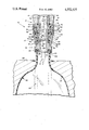
- a nozzle assembly 10 is shown in the accompanying FIGURE to consist generally of a connecting means 12 which connects the assembly to an outlet 14 of pressurized gas.
- a connecting means 12 which connects the assembly to an outlet 14 of pressurized gas.
- four such outlets are provided linearly adjacent to each other and adapted for reciprocal motion above four adjacent blow molds.
- An appropriate nozzle assembly such as that illustrated can be engaged on the outlet or stem support 14 by means of threads 16 for other equivalent engaging features adjacent a lower end 18 of the outlet.
- the nozzle assembly 10 further includes a contacting means 20 for contacting the opening 22 of the parison 24 which is illustrated in phantom prior to the blowing operation and as a bottle 25 conforming to the interior surface 26 of mold 28.
- the contacting means 20 includes a seal means 30 for preventing the escape of pressurized gas during the blowing operation.
- the nozzle assembly 10 further includes between the connecting means 12 and the contacting means 20 means 32 defining an expansible chamber 34 for ensuring engagement between the contacting means 20 and the parison opening 22.
- the expansible chamber 34 is defined by a first member 36 having an inner surface which defines an outer wall of the chamber 34 and a second member 38 which defines a piston movable with respect to member 36 so as to change the volume of the expansible chamber 34.
- the connecting means 12 is seen to include a stem 40 having a threaded outer surface 42 on its upper end 44.
- the threaded surface 42 is adapted to engage the threaded surface 16 of stem support 14.
- a major axial passageway 46 extends downwardly through the center of the stem 40 toward the parison 24. Air or other pressurized gas emanating from the outlet 14 passes through the passageway 46 as shown by arrows A.
- An O-ring or other appropriate seal 48 can be positioned at the base of the threaded surface 42 to prevent the unwanted escape of gas between the stem support 14 and the stem 40.
- a radially outwardly extending flange 50 At the base of the threaded portion 42 of stem 40 is a radially outwardly extending flange 50.
- the flange includes on a lower surface an annualr channel 52 surrounded by a depending wall 54 having a threaded outer surface 56.
- the wall 54 and channel 52 form the upper annular surface of the expansible chamber 34.
- Downwardly angled ports 51 extend from axial passageway 46 through inner wall 53 into the chamber 34.
- the expansible chamber 34 is further defined by cuff 36 which is secured at its upper end 58 to flange 50 by threads 60 engaging the threads 56 of the depending wall 54.
- An inside surface 62 of cuff 36 defines the outer wall of expansible chamber 34.
- the inside surface 62 of cuff 36 includes a step 64 between a larger diametered upper portion containing thread 60 and a smaller diametered lower portion 66 which is right cylindrical in shape and provides a smooth mating surface for the radially outer surface 68 of piston 38.
- the piston 38 includes in its outermost surface 68 a seal 70 shown as a channel containing an O-ring.
- the uppermost surface 72 of piston 38 includes a step 74 separating a radially inward upper portion 76 from the radially outward lower portion 78.
- a compression spring 80 is arranged to extend between channel 52 on the lower surface of flange 50 and the radially outer portion 78 of upper surface 72 of piston 38.
- the spring 80 biases the piston 38 toward a lower position and is intended to ensure initial contact between the seal means 30 and the upper lip of opening 22 of parison 24.
- the piston 38 includes a smooth cylindrical inner surface 82 which includes a seal 84 shown again to be an O-ring within a channel which is slidably engaged on an outer surface 86 of the lower portion 88 of stem 40.
- a lower outer surface 90 defining a skirt of piston 38 having a smaller diameter than outermost surface 68 of piston 38 is slidably engaged with inner surface 92 on the lower portion 94 of cuff 36.
- Surface 90 of piston 38 includes yet another seal 96 shown again as a channel containing an O-ring.
- the contacting means 20 is shown to further include a central axial bore 106 which directs air received from the bore 46 of stem 40 into the open mouth 22 of parison 24 as shown by arrow B.
- the seal means 30 is included within an annular channel 108 on lower surface 110 of the contacting means 20.
- the annular channel 108 includes an inner lip 112 which acts to retain the seal within the channel.
- the seal means 30 is preferably an elastomeric polymer having a durometer of between about 40 and 100 Shore A.
- a particularly usable material is GE RTV silicone which can be cast in the annular channel with the contacting means in a position inverted from that illustrated.
- the nozzle assembly is caused to descend by vertical motion of stem support 14 until the seal means 30 contacts the upper lip of opening 22 of the parison 24.
- the lower extent of motion of the stem support 14 is preferably adjusted such that the contacting means 20 and hence piston 38 moves upwardly with respect to stem 40 and cuff 36 through approximately one-half or more of the free travel. In a typical installation, a variation of up to one-quarter of an inch can be tolerated. In general, parisons are formed with sufficient regularity that variations are generally less than about ten-thousandths of an inch.
- a gaseous blowing medium typically air
- air is quickly injected through outlet 14 and into axial passageway 46.
- the downwardly angled ports 51 extending from the axial passageway 46 through the inner wall 53 of chamber 34 causes a quick increase in pressure within the chamber 34.
- This increase in pressure within chamber 34 exerts a force on the annular pressure surface 72 of piston 38 causing it to press downwardly to ensure a complete and full seal by the sealing means 30 on the upper lip of opening 22.
- the pressure within the parison builds causing it to expand outwardly to conform to the walls 26 of mold 28 and form bottle 25.
- the pressure within the nozzle assembly and blown bottle 25 is relieved through a relief valve, not shown, and the stem support 14 moved vertically upward so as to remove contact between the blown bottle 25 and the contacting means 20.
- the blown bottle 25 is then removed from the mold 28 and a new parison 24 situated therein ready for a repeat of the blowing cycle.
Landscapes
- Engineering & Computer Science (AREA)
- Manufacturing & Machinery (AREA)
- Mechanical Engineering (AREA)
- Blow-Moulding Or Thermoforming Of Plastics Or The Like (AREA)
Abstract
Description
Claims (8)
Priority Applications (1)
| Application Number | Priority Date | Filing Date | Title |
|---|---|---|---|
| US06/659,161 US4552527A (en) | 1984-10-09 | 1984-10-09 | Nozzle assembly |
Applications Claiming Priority (1)
| Application Number | Priority Date | Filing Date | Title |
|---|---|---|---|
| US06/659,161 US4552527A (en) | 1984-10-09 | 1984-10-09 | Nozzle assembly |
Publications (1)
| Publication Number | Publication Date |
|---|---|
| US4552527A true US4552527A (en) | 1985-11-12 |
Family
ID=24644297
Family Applications (1)
| Application Number | Title | Priority Date | Filing Date |
|---|---|---|---|
| US06/659,161 Expired - Fee Related US4552527A (en) | 1984-10-09 | 1984-10-09 | Nozzle assembly |
Country Status (1)
| Country | Link |
|---|---|
| US (1) | US4552527A (en) |
Cited By (24)
| Publication number | Priority date | Publication date | Assignee | Title |
|---|---|---|---|---|
| US4923385A (en) * | 1986-07-09 | 1990-05-08 | Krauss-Maffei A.G. | Blow molding machine |
| FR2764544A1 (en) * | 1997-06-16 | 1998-12-18 | Sidel Sa | NOZZLE FOR BLOWING PLASTIC CONTAINERS AND INSTALLATION PROVIDED WITH SUCH A NOZZLE |
| US20020037338A1 (en) * | 2000-07-24 | 2002-03-28 | Lisch G. David | Apparatus for stabilizing bottle upon demolding |
| US20050175731A1 (en) * | 2004-02-09 | 2005-08-11 | Fu-Chuan Chiang | Nozzle for a blow molding machine |
| FR2876942A1 (en) * | 2004-10-22 | 2006-04-28 | Sidel Sas | BLOWING INSTALLATION FOR THE MANUFACTURE OF THERMOPLASTIC CONTAINERS |
| FR2889673A1 (en) * | 2005-08-12 | 2007-02-16 | Sidel Sas | BLOWING INSTALLATION COMPRISING A PIPE EQUIPPED WITH A LIP SEAL |
| EP1970190A2 (en) * | 2007-03-14 | 2008-09-17 | Krones Ag | Device for handling containers |
| WO2008101468A3 (en) * | 2007-02-23 | 2008-11-13 | Khs Corpoplast Gmbh & Co Kg | Method and apparatus for blow-molding receptacles |
| FR2922809A1 (en) * | 2007-10-24 | 2009-05-01 | Nestle Waters Man & Technology | AIR CARTRIDGE DEVICE, BLOW MOLDING APPARATUS, METHOD FOR UPGRADING SUCH APPARATUS, AND METHOD OF BLOWING BOTTLE |
| EP2127851A1 (en) * | 2008-05-29 | 2009-12-02 | Krones AG | Device and method for expanding containers with seal at the opening of the container |
| WO2009007315A3 (en) * | 2007-07-10 | 2010-01-21 | Krones Ag | Blowing apparatus for expanding containers |
| DE102008036103A1 (en) * | 2008-08-04 | 2010-02-11 | Krones Ag | Device for expanding containers |
| US20100143531A1 (en) * | 2007-02-16 | 2010-06-10 | Sidel Paarticipations | Nozzle for a container manufacturing machine |
| US20110287126A1 (en) * | 2010-05-20 | 2011-11-24 | Florian Geltinger | Apparatus for shaping plastic preforms, comprising a sterile chamber |
| US20120114783A1 (en) * | 2009-04-21 | 2012-05-10 | Sidel Participations | nozzle for a machine for manufacturing containers |
| WO2013107657A1 (en) * | 2012-01-19 | 2013-07-25 | Khs Corpoplast Gmbh | Method and device for blow-moulding containers |
| US20140091500A1 (en) * | 2005-03-08 | 2014-04-03 | Silgan Plastics Llc | Bottle with extended neck finish and method of making same |
| CN104039526A (en) * | 2011-12-21 | 2014-09-10 | 阿美科有限责任公司 | Sealing systems for molding machines |
| WO2014166895A1 (en) * | 2013-04-09 | 2014-10-16 | Nestec S.A. | Apparatus and method for fabricating and filling containers |
| EP2801469A1 (en) * | 2013-05-07 | 2014-11-12 | Nestec S.A. | Apparatus and method for fabricating containers |
| US20150151468A1 (en) * | 2012-03-27 | 2015-06-04 | Sidel Participations | Nozzle for forming containers provided with an interchangeable tip in which elements matching the format of the neck of the container are embedded |
| US20150328824A1 (en) * | 2012-12-28 | 2015-11-19 | Yoshino Kogyosho Co., Ltd. | Blow molding device |
| DE102006039962B4 (en) * | 2006-08-25 | 2016-02-18 | Khs Corpoplast Gmbh | Method and apparatus for blow molding containers |
| EP3778185A4 (en) * | 2018-04-03 | 2021-12-15 | Nissei Asb Machine Co., Ltd. | BLOW MOLDING DIE AND BLOW MOLDING DEVICE |
Citations (18)
| Publication number | Priority date | Publication date | Assignee | Title |
|---|---|---|---|---|
| US890013A (en) * | 1907-09-04 | 1908-06-09 | Lloyd S Atkinson | Railway-switch lock. |
| UST890013I4 (en) | 1971-02-01 | 1971-09-21 | Apparatus for blow molding undercut articles | |
| US3712784A (en) * | 1970-03-27 | 1973-01-23 | M Siard | Apparatus for blow molding a preform in a mold with a sterile gas |
| US3737275A (en) * | 1972-01-17 | 1973-06-05 | Owens Illinois Inc | Blow needle and valve |
| US3866636A (en) * | 1973-01-15 | 1975-02-18 | Dover Corp | Sealing arrangement for liquid dispensing nozzle having vapor recovery |
| US3884277A (en) * | 1970-08-29 | 1975-05-20 | Holstein & Kappert Maschf | Apparatus for filling beer cans or the like |
| US3895897A (en) * | 1974-03-04 | 1975-07-22 | Monsanto Co | Blow needle assembly |
| US3974865A (en) * | 1975-01-21 | 1976-08-17 | Emco Wheaton Inc. | Vapor collecting nozzle |
| US4009980A (en) * | 1975-07-23 | 1977-03-01 | Package Machinery Company | Injection blow molding machine having movable parison pins |
| US4056131A (en) * | 1975-02-27 | 1977-11-01 | Healy James W | Vapor control in a fuel dispensing nozzle |
| US4070141A (en) * | 1976-11-26 | 1978-01-24 | Leonard Benoit Ryder | Apparatus for injection blow molding |
| US4196759A (en) * | 1976-06-17 | 1980-04-08 | Dover Corporation | Liquid dispensing nozzle having a sealing arrangement for vapor recovery |
| US4224913A (en) * | 1979-08-13 | 1980-09-30 | General Motors Corporation | Vehicle air-fuel controller having hot restart air/fuel ratio adjustment |
| US4382760A (en) * | 1981-04-24 | 1983-05-10 | Cincinnati Milacron Inc. | Apparatus for high rate production of biaxially oriented thermoplastic articles |
| US4403940A (en) * | 1981-10-28 | 1983-09-13 | The Continental Group, Inc. | Blow head valve |
| US4412806A (en) * | 1981-05-15 | 1983-11-01 | The Broadway Companies, Inc. | Parison ejector for an injection molding apparatus |
| US4422843A (en) * | 1981-03-13 | 1983-12-27 | Katashi Aoki | Injection stretching blow molding machine |
| US4456447A (en) * | 1982-03-05 | 1984-06-26 | Cincinnati Milacron Inc. | Carrier with exchangeable chuck |
-
1984
- 1984-10-09 US US06/659,161 patent/US4552527A/en not_active Expired - Fee Related
Patent Citations (18)
| Publication number | Priority date | Publication date | Assignee | Title |
|---|---|---|---|---|
| US890013A (en) * | 1907-09-04 | 1908-06-09 | Lloyd S Atkinson | Railway-switch lock. |
| US3712784A (en) * | 1970-03-27 | 1973-01-23 | M Siard | Apparatus for blow molding a preform in a mold with a sterile gas |
| US3884277A (en) * | 1970-08-29 | 1975-05-20 | Holstein & Kappert Maschf | Apparatus for filling beer cans or the like |
| UST890013I4 (en) | 1971-02-01 | 1971-09-21 | Apparatus for blow molding undercut articles | |
| US3737275A (en) * | 1972-01-17 | 1973-06-05 | Owens Illinois Inc | Blow needle and valve |
| US3866636A (en) * | 1973-01-15 | 1975-02-18 | Dover Corp | Sealing arrangement for liquid dispensing nozzle having vapor recovery |
| US3895897A (en) * | 1974-03-04 | 1975-07-22 | Monsanto Co | Blow needle assembly |
| US3974865A (en) * | 1975-01-21 | 1976-08-17 | Emco Wheaton Inc. | Vapor collecting nozzle |
| US4056131A (en) * | 1975-02-27 | 1977-11-01 | Healy James W | Vapor control in a fuel dispensing nozzle |
| US4009980A (en) * | 1975-07-23 | 1977-03-01 | Package Machinery Company | Injection blow molding machine having movable parison pins |
| US4196759A (en) * | 1976-06-17 | 1980-04-08 | Dover Corporation | Liquid dispensing nozzle having a sealing arrangement for vapor recovery |
| US4070141A (en) * | 1976-11-26 | 1978-01-24 | Leonard Benoit Ryder | Apparatus for injection blow molding |
| US4224913A (en) * | 1979-08-13 | 1980-09-30 | General Motors Corporation | Vehicle air-fuel controller having hot restart air/fuel ratio adjustment |
| US4422843A (en) * | 1981-03-13 | 1983-12-27 | Katashi Aoki | Injection stretching blow molding machine |
| US4382760A (en) * | 1981-04-24 | 1983-05-10 | Cincinnati Milacron Inc. | Apparatus for high rate production of biaxially oriented thermoplastic articles |
| US4412806A (en) * | 1981-05-15 | 1983-11-01 | The Broadway Companies, Inc. | Parison ejector for an injection molding apparatus |
| US4403940A (en) * | 1981-10-28 | 1983-09-13 | The Continental Group, Inc. | Blow head valve |
| US4456447A (en) * | 1982-03-05 | 1984-06-26 | Cincinnati Milacron Inc. | Carrier with exchangeable chuck |
Cited By (56)
| Publication number | Priority date | Publication date | Assignee | Title |
|---|---|---|---|---|
| US4923385A (en) * | 1986-07-09 | 1990-05-08 | Krauss-Maffei A.G. | Blow molding machine |
| US6464486B1 (en) * | 1997-06-16 | 2002-10-15 | Sidel | Nozzle for blow molding plastic containers and installation provided with same |
| FR2764544A1 (en) * | 1997-06-16 | 1998-12-18 | Sidel Sa | NOZZLE FOR BLOWING PLASTIC CONTAINERS AND INSTALLATION PROVIDED WITH SUCH A NOZZLE |
| WO1998057794A1 (en) * | 1997-06-16 | 1998-12-23 | Sidel S.A. | Nozzle for blow moulding plastic containers and installation provided with same |
| CN1080183C (en) * | 1997-06-16 | 2002-03-06 | 赛德尔公司 | Nozzle for blow moulding plastic containers and installation provided with same |
| US20020037338A1 (en) * | 2000-07-24 | 2002-03-28 | Lisch G. David | Apparatus for stabilizing bottle upon demolding |
| US6709624B2 (en) * | 2000-07-24 | 2004-03-23 | Schmalbach-Lubeca Ag | Apparatus for stabilizing bottle upon demolding |
| US20050175731A1 (en) * | 2004-02-09 | 2005-08-11 | Fu-Chuan Chiang | Nozzle for a blow molding machine |
| FR2876942A1 (en) * | 2004-10-22 | 2006-04-28 | Sidel Sas | BLOWING INSTALLATION FOR THE MANUFACTURE OF THERMOPLASTIC CONTAINERS |
| WO2006045925A1 (en) * | 2004-10-22 | 2006-05-04 | Sidel Participations | Blow moulding system for the manufacture of thermoplastic receptacles |
| US7563092B2 (en) | 2004-10-22 | 2009-07-21 | Sidel Participations | Blow molding system for the manufacture of thermoplastic receptacles |
| US20080286402A1 (en) * | 2004-10-22 | 2008-11-20 | Sidel Participations | Blow Molding System for the Manufacture of Thermoplastic Receptacles |
| US20140091500A1 (en) * | 2005-03-08 | 2014-04-03 | Silgan Plastics Llc | Bottle with extended neck finish and method of making same |
| US10035292B2 (en) | 2005-03-08 | 2018-07-31 | Silgan Plastics Llc | Bottle with extended neck finish and method of making same |
| US10589454B2 (en) | 2005-03-08 | 2020-03-17 | Silgan Plastics Llc | Bottle with extended neck finish and method of making same |
| US9248603B2 (en) * | 2005-03-08 | 2016-02-02 | Silgan Plastics Llc | Bottle with extended neck finish and method of making same |
| US7922962B2 (en) | 2005-08-12 | 2011-04-12 | Sidel Participations | Blowing plant comprising a nozzle provided with a lip sealing joint |
| US20100151073A1 (en) * | 2005-08-12 | 2010-06-17 | Sidel Partiipations | Blowing plant comprising a nozzle provided with a lip sealing joint |
| FR2889673A1 (en) * | 2005-08-12 | 2007-02-16 | Sidel Sas | BLOWING INSTALLATION COMPRISING A PIPE EQUIPPED WITH A LIP SEAL |
| WO2007020137A1 (en) * | 2005-08-12 | 2007-02-22 | Sidel Participations | Blowing plant comprising a nozzle provided with a lip sealing joint |
| CN101237983B (en) * | 2005-08-12 | 2010-05-19 | 西德尔合作公司 | Blowing installation with a blow pipe fitted with a lip seal |
| DE102006039962B4 (en) * | 2006-08-25 | 2016-02-18 | Khs Corpoplast Gmbh | Method and apparatus for blow molding containers |
| US20100143531A1 (en) * | 2007-02-16 | 2010-06-10 | Sidel Paarticipations | Nozzle for a container manufacturing machine |
| US8297966B2 (en) * | 2007-02-16 | 2012-10-30 | Sidel Participations | Nozzle for a container manufacturing machine |
| WO2008101468A3 (en) * | 2007-02-23 | 2008-11-13 | Khs Corpoplast Gmbh & Co Kg | Method and apparatus for blow-molding receptacles |
| US20080224362A1 (en) * | 2007-03-14 | 2008-09-18 | Hansjoerg Halbo | Device for treating containers |
| US7758333B2 (en) | 2007-03-14 | 2010-07-20 | Krones Ag | Device for treating containers |
| EP1970190A2 (en) * | 2007-03-14 | 2008-09-17 | Krones Ag | Device for handling containers |
| CN101801642A (en) * | 2007-07-10 | 2010-08-11 | 克朗斯股份公司 | Blowing apparatus for expanding containers |
| US20100176540A1 (en) * | 2007-07-10 | 2010-07-15 | Wolfgang Sperka | Blowing apparatus for expanding containers |
| US8349246B2 (en) | 2007-07-10 | 2013-01-08 | Krones Ag | Blowing apparatus for expanding containers |
| CN101801642B (en) * | 2007-07-10 | 2013-08-28 | 克朗斯股份公司 | Blowing apparatus for expanding containers |
| WO2009007315A3 (en) * | 2007-07-10 | 2010-01-21 | Krones Ag | Blowing apparatus for expanding containers |
| FR2922809A1 (en) * | 2007-10-24 | 2009-05-01 | Nestle Waters Man & Technology | AIR CARTRIDGE DEVICE, BLOW MOLDING APPARATUS, METHOD FOR UPGRADING SUCH APPARATUS, AND METHOD OF BLOWING BOTTLE |
| EP2127851A1 (en) * | 2008-05-29 | 2009-12-02 | Krones AG | Device and method for expanding containers with seal at the opening of the container |
| DE102008036103A1 (en) * | 2008-08-04 | 2010-02-11 | Krones Ag | Device for expanding containers |
| EP2151310A3 (en) * | 2008-08-04 | 2014-01-29 | Krones AG | Device for expanding containers |
| US20120114783A1 (en) * | 2009-04-21 | 2012-05-10 | Sidel Participations | nozzle for a machine for manufacturing containers |
| US8579626B2 (en) * | 2009-04-21 | 2013-11-12 | Sidel Participations | Nozzle for a machine for manufacturing containers |
| US8708680B2 (en) * | 2010-05-20 | 2014-04-29 | Krones Ag | Apparatus for shaping plastic preforms, comprising a sterile chamber |
| US20110287126A1 (en) * | 2010-05-20 | 2011-11-24 | Florian Geltinger | Apparatus for shaping plastic preforms, comprising a sterile chamber |
| CN104039526B (en) * | 2011-12-21 | 2017-08-08 | 帝斯克玛股份有限公司 | Sealing systems for molding machines |
| CN104039526A (en) * | 2011-12-21 | 2014-09-10 | 阿美科有限责任公司 | Sealing systems for molding machines |
| WO2013107657A1 (en) * | 2012-01-19 | 2013-07-25 | Khs Corpoplast Gmbh | Method and device for blow-moulding containers |
| US20150151468A1 (en) * | 2012-03-27 | 2015-06-04 | Sidel Participations | Nozzle for forming containers provided with an interchangeable tip in which elements matching the format of the neck of the container are embedded |
| US9364991B2 (en) * | 2012-03-27 | 2016-06-14 | Sidel Participations | Nozzle for forming containers provided with an interchangeable tip in which elements matching the format of the neck of the container are embedded |
| US20150328824A1 (en) * | 2012-12-28 | 2015-11-19 | Yoshino Kogyosho Co., Ltd. | Blow molding device |
| US9579841B2 (en) * | 2012-12-28 | 2017-02-28 | Yoshino Kogyosho Co., Ltd. | Blow molding device |
| US10040237B2 (en) | 2013-04-09 | 2018-08-07 | Discma Ag | Apparatus and method for fabricating and filling containers |
| WO2014166895A1 (en) * | 2013-04-09 | 2014-10-16 | Nestec S.A. | Apparatus and method for fabricating and filling containers |
| JP2016520454A (en) * | 2013-05-07 | 2016-07-14 | 株式会社吉野工業所 | Apparatus and method for manufacturing containers |
| WO2014180805A1 (en) * | 2013-05-07 | 2014-11-13 | Nestec S.A. | Apparatus and method for fabricating containers |
| EP2801469A1 (en) * | 2013-05-07 | 2014-11-12 | Nestec S.A. | Apparatus and method for fabricating containers |
| US10183438B2 (en) | 2013-05-07 | 2019-01-22 | Discma Ag | Apparatus and method for fabricating containers |
| EP3778185A4 (en) * | 2018-04-03 | 2021-12-15 | Nissei Asb Machine Co., Ltd. | BLOW MOLDING DIE AND BLOW MOLDING DEVICE |
| US11247382B2 (en) | 2018-04-03 | 2022-02-15 | Nissei Asb Machine Co., Ltd. | Blow molding mold and blow molding apparatus |
Similar Documents
| Publication | Publication Date | Title |
|---|---|---|
| US4552527A (en) | Nozzle assembly | |
| AU698217B2 (en) | Sealing device between a parison for a recipient made of plastic material and a blow moulding nozzle, and machine for blow moulding recipients equipped with such a device | |
| CA1213111A (en) | Parison stretcher | |
| EP0184264B1 (en) | Method for blow-molding a container having a neck-portion with internal attachment means | |
| EP0870593B1 (en) | Method for injection and stretch blow molding articles | |
| MX2007014948A (en) | HOLLOW BODY BLOWING INSTALLATION. | |
| US4397629A (en) | Apparatus for drawing mouth-neck portions of synthetic resin bottles | |
| US7758333B2 (en) | Device for treating containers | |
| US4753591A (en) | Apparatus for forming the neck finish of blow molded containers | |
| CN105102334A (en) | Stretch-blow moulded plastic container and stretch-blow moulding method | |
| US5124110A (en) | Temperature adjusting and compressing in injection stretch blow molding for forming raised portions in the container produced | |
| WO1995029804A1 (en) | Biaxial orientation blow molding method and preform holding jig | |
| US4317793A (en) | Process for the production of oriented hollow bodies | |
| US4497758A (en) | Method of forming bottle neck finish for accepting a snap-in closure | |
| US7922962B2 (en) | Blowing plant comprising a nozzle provided with a lip sealing joint | |
| US5454707A (en) | Non-scuffing, non-sticking blow core for stretch blow molding machines | |
| US4662928A (en) | Apparatus for forming a glass bottle finish | |
| US5792231A (en) | Baffle assembly | |
| GB1517414A (en) | Process for the production of blow-moulded oriented hollow synthetic resin material bodies and apparatus for use in this process | |
| US3466701A (en) | Apparatus for blow molding bottles | |
| CN215750700U (en) | Neck mold mechanism of blow molding machine | |
| US4575331A (en) | Transport neck ring | |
| ES2181881T3 (en) | REFRIGERATION SYSTEM FOR MOLDS USED IN THE GLASS MANUFACTURING INDUSTRY, SUCH MOLD MACHINING PROCEDURE AND ADAPTATION PROCEDURE OF THE COOLING SYSTEM TO DIFFERENT MOLDS TO PASS THE PRODUCTION OF A GLASS CONTAINER TO ANOTHER GLASS | |
| CN101653984B (en) | Blow molding device (1) of containers | |
| CN113165252B (en) | Blow molding device |
Legal Events
| Date | Code | Title | Description |
|---|---|---|---|
| AS | Assignment |
Owner name: SEWELL PLASTICS, INC., 445 GREAT SOUTHWEST PARKWAY Free format text: ASSIGNMENT OF ASSIGNORS INTEREST.;ASSIGNOR:HUNTER, BURNIS L.;REEL/FRAME:004323/0315 Effective date: 19840926 |
|
| CC | Certificate of correction | ||
| AS | Assignment |
Owner name: NEW HOLLAND INC., 500 DILLER AVE., NEW HOLLAND, PA Free format text: ASSIGNMENT OF ASSIGNORS INTEREST.;ASSIGNOR:SPERRY CORPORATION A CORP. OF DE;REEL/FRAME:004700/0042 Effective date: 19860326 Owner name: NEW HOLLAND INC., A CORP. OF DE,PENNSYLVANIA Free format text: ASSIGNMENT OF ASSIGNORS INTEREST;ASSIGNOR:SPERRY CORPORATION A CORP. OF DE;REEL/FRAME:004700/0042 Effective date: 19860326 |
|
| AS | Assignment |
Owner name: FORD NEW HOLLAND, INC., 500 DILLER AVENUE, NEW HOL Free format text: ASSIGNMENT OF ASSIGNORS INTEREST.;ASSIGNOR:NEW HOLLAND INC., A CORP. OF DE.;REEL/FRAME:004879/0501 Effective date: 19871222 Owner name: FORD NEW HOLLAND, INC., A CORP. OF DE., PENNSYLVAN Free format text: ASSIGNMENT OF ASSIGNORS INTEREST;ASSIGNOR:NEW HOLLAND INC., A CORP. OF DE.;REEL/FRAME:004879/0501 Effective date: 19871222 |
|
| FPAY | Fee payment |
Year of fee payment: 4 |
|
| AS | Assignment |
Owner name: CONSTAR PLASTICS INC. Free format text: CHANGE OF NAME;ASSIGNOR:SEWELL PLASTICS, INC.;REEL/FRAME:006085/0656 Effective date: 19911203 |
|
| AS | Assignment |
Owner name: CONSTAR PLASTICS INC. Free format text: CHANGE OF NAME;ASSIGNOR:SEWELL PLASTICS, INC.;REEL/FRAME:006115/0054 Effective date: 19911203 |
|
| FPAY | Fee payment |
Year of fee payment: 8 |
|
| REMI | Maintenance fee reminder mailed | ||
| LAPS | Lapse for failure to pay maintenance fees | ||
| FP | Lapsed due to failure to pay maintenance fee |
Effective date: 19971112 |
|
| STCH | Information on status: patent discontinuation |
Free format text: PATENT EXPIRED DUE TO NONPAYMENT OF MAINTENANCE FEES UNDER 37 CFR 1.362 |