US454151A - The honnis peters co - Google Patents
The honnis peters co Download PDFInfo
- Publication number
- US454151A US454151A US454151DA US454151A US 454151 A US454151 A US 454151A US 454151D A US454151D A US 454151DA US 454151 A US454151 A US 454151A
- Authority
- US
- United States
- Prior art keywords
- water
- chamber
- pipe
- vessel
- pump
- Prior art date
- Legal status (The legal status is an assumption and is not a legal conclusion. Google has not performed a legal analysis and makes no representation as to the accuracy of the status listed.)
- Expired - Lifetime
Links
- XLYOFNOQVPJJNP-UHFFFAOYSA-N water Substances O XLYOFNOQVPJJNP-UHFFFAOYSA-N 0.000 description 28
- 238000004891 communication Methods 0.000 description 14
- 230000007246 mechanism Effects 0.000 description 6
- 238000010276 construction Methods 0.000 description 5
- 238000005086 pumping Methods 0.000 description 4
- 230000033001 locomotion Effects 0.000 description 3
- 241000251468 Actinopterygii Species 0.000 description 2
- 238000005188 flotation Methods 0.000 description 2
- 238000009432 framing Methods 0.000 description 2
- 241000507564 Aplanes Species 0.000 description 1
- 241000220317 Rosa Species 0.000 description 1
- 229910000831 Steel Inorganic materials 0.000 description 1
- 238000013459 approach Methods 0.000 description 1
- 230000003190 augmentative effect Effects 0.000 description 1
- 238000007599 discharging Methods 0.000 description 1
- YDTFRJLNMPSCFM-YDALLXLXSA-M levothyroxine sodium anhydrous Chemical compound [Na+].IC1=CC(C[C@H](N)C([O-])=O)=CC(I)=C1OC1=CC(I)=C(O)C(I)=C1 YDTFRJLNMPSCFM-YDALLXLXSA-M 0.000 description 1
- 230000001105 regulatory effect Effects 0.000 description 1
- 230000000630 rising effect Effects 0.000 description 1
- 235000002020 sage Nutrition 0.000 description 1
- 239000007787 solid Substances 0.000 description 1
- 239000010959 steel Substances 0.000 description 1
- 239000002023 wood Substances 0.000 description 1
Images


Classifications
-
- B—PERFORMING OPERATIONS; TRANSPORTING
- B63—SHIPS OR OTHER WATERBORNE VESSELS; RELATED EQUIPMENT
- B63H—MARINE PROPULSION OR STEERING
- B63H25/00—Steering; Slowing-down otherwise than by use of propulsive elements; Dynamic anchoring, i.e. positioning vessels by means of main or auxiliary propulsive elements
- B63H25/46—Steering or dynamic anchoring by jets or by rudders carrying jets
Definitions
- TH Num-us sans on., Fumo-umu., wwmnamn, n, c.
- OurV invention relates to the propulsion of floating craft by hydraulic power7 alid more particularly to that inode of propulsion in Which Water is drawn in at one end of the vessel and ejected at the otherin an unbroken stream and under pressure; and it consists in structural features'and combinations of cooperative elements, as Will now be fully described, reference being had to the accompanying drawings, in Whicl Figure 1 is a sectional side elevation, and Fig. 2, a plan of a vessel Iitted with our improved apparatus for propelling ⁇ it and for other purposes. In both these views the pumping engines,7 as they may be called, are drawn larger in proportion to the size of the vessel than would actually be the case in practice, While the boilers, on the other hand,
- Fig. 3 is a front elevation
- Fig. 4 a side elevation
- Fig. 5 aplan
- Fig. 6 is a side elevation illustrating similar apparatus arranged horizontally
- Fig. 7 is a detail-view of a certain valve-operating gear, hereinafter described.
- Fig. S is a plan of the end of the dischargeconduit, illustrating the steering devices and the valves connected therewith. Figs.
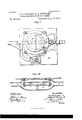
- Figs. 9 and l0 are respectivelya side elevation and a sectional plan of a guard which is provided over the end of the orifice of the inlet-conduit for the purpose of preventing the entrance of any floating bodies, such as fish or logs of Wood.
- Fig. 11 is a side elevation of a valve and raising-gear therefor, which We provide in the main conduits to enable Water to be pumped out of the hold in the event of the ship springing a leak.
- Figs. 12 and 13 are diagrainniatic views illustrating the operation of our pumping engines or apparatus
- Fig. 14 is a detached side elevation of a portion of our improved apparatus, illustrating a modified construction of saine.
- the water of flotation is drawn in, at the lowest possible point forward, as at A in Fig. 1, forcing suoli Water in one unbroken stream in the form of a rope, as it were, through the vessel and eventually discharging it with augmented force through the tapering tube or conduit B at the stern.
- this tube B With a gradually-decreasing area in cross-section the pressure of the Water therein Will be increased and it will form what may be described as a solid piston of Water, which will act against the water of flotation in a very eifective manner.
- conduit C leading from the bows to the pump, and the conduit B, leading from said pump to the stern, are bolted or riveted to the ribs or framing of the vessel and constitute the keelson thereof, and by reason of their tubular form impart a strength and rigidity to the vessel, which have hitherto been unattainable.
- valves hereinbefore mentioned as being provided for the purpose of allowing the vessel to be pumped free of Water in the event'of a leak being sprung or a collision taking place are illustrated in position at D in Figs. 1 and 2. They may consist, as shown in detail in Fig. l1, of a simple disk-valve adapted to be raised or lowered by a screwthreaded rod d, passing up through a protecting tube or sleeve d. to the deck E of the vessel, Where said rod may be rotated by means of a suitable key fitted over its squared end d2, Which is preferably let in ush with said deck, as shown. The Water so pumped out of the vessels hold would thus be employed for propelling her.
- a rolled-steel grating F formed of bars f, Figs. 9 and 10, of triangular section, set with their apexes in the direction of the vessels travel, so that they IOO will offer but very little resistance thereto.
- These bars are connected with a framing adapted to be moved vertically in the guides f secured on either side of the bows, in order that the grating may be drawn up out of the way when not required-as, for instance, when the vessel is going astern.
- the rod f2 is provided for such raising and lowering purposes and is so arranged that by its 1o means the grating F can readily be dropped into position over the orifice of the conduit C, in order to prevent large fish, floating logs, or other obstacles from being drawn therein.
- the conduit B is connected at the stern of I5 the vessel with two other shorter conduits G G, Figs. 2 and S, which pass out at said stern on either side of the main conduit B, and are each provided with a suitable valve, such as g g, either of which may be opened as a pas- 2o sage for the outrushing water at the same time that the main conduit B is closed or partially so.
- a suitable valve such as g g, either of which may be opened as a pas- 2o sage for the outrushing water at the same time that the main conduit B is closed or partially so.
- These two valves g g are preferably connected with some gearing or apparatus whereby they maybe worked in unisonthat is, they may be so arranged that when one of theln is open, whether partially or entirely so, the other will be completely shutthus enabling the vessel to be rapidly turned in either direction by simply regulating the 3o flow of water therethrough.
- the hydraulic 6o chamber In some convenient position-as, for instance, beneath the platform K, supporting the pumping-engines-we provide what will hereinafter be referred to as the hydraulic 6o chamber. It is indicated by the let-ter L and is in communication with both conduits B and C, as well as with both the upper and lower portions of the pump-cylinder I. It may be of any convenient construction and may, for example, be either square, as illustrated in the majority of the figures, or may bc oval, as illustrated in Fig. li, so as to better allow the flow of water therethrough.
- the opening 1*, connecting this chamber L with the lower portion of the pump-cylinder, is provided with an outlet-valve lof any suitable construetion, and the lower end of the pipe I', connecting said chamber with thevupper end of said cylinder, is similarly furnished with a corresponding valve l2.
- the ends of the two conduits B and C may the one be opened and the other closed, or both be partially opened by means of the double elack-valve l) c, which is pivoted between a pair of lugs b', projecting upwardly from the bottom of the chamber L in such a manner that said valve may be partially rotated upon its pivot, so as to throw it over from one side to the other in order to close one conduit and open the other, or (under some circumstances) to partially open both of these valves.
- This latter provision is made for the purpose of enabling the engines to be tested, so as to ascertain whether they are in proper workin g order before starting the vessel upon her voyage-that is, while she is stationary-as, for instance, when moored alongside a pier.
- any convenient position alongside the pump-cylinder I we arrange a condensing receiving-chamber M, which is in communication with both the upper and lower ends of the pump-cylinder I through the two tubes i2 and t3, whose ends are closed by inlet-valves i" and i5 within said pump-cylinder.
- This condensing and receiving chamber M is also in communication with the two conduits B and C through the two branch tubes nz and m', whose ends where they project into the said condensing-chamber are either closed or opened by means of a double clack-valve mi m3, which is similar in construction to the valve b c in the hydraulic chamber L.
- This condensing and receiving chamber is capable of holding suiiieient water to fill the pumpcylinder at any time and at any part of the stroke in order that the engines may start work immediately to propel the vessel either backward or forward.
- the exhaust-pipe yn passes from the exhaust-port of the steam-cylinder Il down to the upper portion N of the condensing and receiving chamber.
- This upper portion is in communication with the lower portion of said chamber by a small snift-valve 71,', which prevents the incoming water from rising in the exhaust-tube, while the steam is drawn olf at each stroke into the receiving-chamber M and will be condensed in so eifective a manner (owing to the immense volume of water passin through) that we shall be enabled to work our cylinders with steam at a very high pressure-in fact, at a pressure which will only be limited by considerations of safety.-
- An arm o upon a throttle-valve provided in the steam-pipe O is connected by rod o with a short arm o2 of the tappet-leverj, so that said throttle-valve will be caused to work as IOO IIO
- valves such, for instance, as that illustrated in Fig. 14, which consists of a pair of stop-valves, connected the one to the other and operated by means of a pinion gearing with a rack formed'upon the under side of their connecting-piece.
- IVe provide against fire by connecting small pipes P, Fig. 1, to the conduits B and C, leading them into different parts of the vessel and providing them with rose or other j ets p and with stop-cocks p', whereby water may be pumped into the hold or wherever else the re may have started.
- valves c and m2 are closed and the valves b and m3 are opened to passage of the water, which will be drawn through the conduit C into the condensing and receiving chamber M, and will from thence pass into either the upper or the lower part of the pump-cylinder I, according to Whether the p ump-piston is traveling' up or down, and will finally be forced into the hydraulic chamber L, and from thence out through the conical discharge-conduit B at the stern of the vessel.
- This operation will be clearly understood by reference to Figs. 12 and 13, wherein the path of the water is clearly indica-ted by arrows in both the up and down stroke of the pump-piston, respectively.
- Vhen it is required to reverse the motion of the vessel, it is only necessary to alter the positions of the two double clack-valves b c and m2 m3, so that the water will be drawn in through the conduit B and expelled through conduit C, thus reversing the travel of the vessel without stopping' the engines for a single revolution. It will be readily understood that these facilities for reversal will be of very great practical utility in stopping the vessel quickly in the case of a collision or when some other similar danger appears to be imminent.
- a suction and force pipe having its inlets and outlets at the bow and stern, respectively, in substantially the same horizontal plane, the forcing end of said pipe being provided with a valved port opening into the hold of the vessel, in combination with a suction and force pump interposed in said pipe between the suction end thereof and said valved port, receivin g and delivery chambers, both in communication with the suction and .force pipe, connections provided with suitable check-valves between the chambers and both ends of the pum p-cylinder, and a valve mechanism in each of said chambers adapted to reverse the flow of water through said devices, for the purpose set forth.
- a suction and force pipe having its inlets and outlets at the bow and stern, respectively, in substantially the same horizontal plane, the forcing end of said pipe being provided with a valved port opening into the hold of the vessel, a stand-pipe connected with the suction and force pipe forward of said valved port, said pipe having valved branches provided with j et-nozzles extending to the various compartments of the vessel, in combination with a pump interposed in the suction and force-pipe forward of the stand-pipe, receiving and delivery chambers both in communication with the suction and force pipe, and with both ends of the pump-cylinder, and a valve mechanism adapted to reverse the iiow of water through the.suction and force pipe, for the purpose set forth.
- a suction and force pump As a means for propelling vessels, a suction and force pump, a water-chamber in communication with the opposite ends of the pump-cylinder through the medium of valved communications, a suction-pipe having its inlet at the bows and its outlet within the water-chamber, a forcing-pipe having its outlet at the stern and its inlet also within the water-chamber, and a double valve interposed between the outlet of the suction-pipe and the inlet of the forcing-pipe and adapted to co-operate therewith and direct and control the flow of water therethrough, substantially as and for t-he purposes specified.
- a suction and force pump As a means for propelling vessels, a suction and force pump, a water-chamber in communication with the opposite ends of the pu nip-cylinder through the medium of valved communications, a suction-pipe having its inlet at the bows and its outlet within the water-chamber, a forcing-pipe having its outlet at the stern and its inlet also within the water-chamber, and a double Valve interposed between the outlet of the suction-pipe and the inlet of the forcing-pipe and adapted to co-operate therewith and direct and control the flow of water therethrough, an auxiliary water-chamber, valved connections between the same and the opposite ends of the pump-cylinder, the branches m and fm, con necting said auxiliary Water-chamber with the suction and forcing pipes, respectively, and a double valve m3 m2, arranged within the auxiliary water-chamber and adapted to co-operate with said branches m and fm, to direct and cont-rol the fiow of Water
- a suction and force pump As a means for propelling vessels, a suction and force pump, a water-chamber in communication with the opposite ends of the pu nip-cylinder through the medium of valved connections, avsuctionpipe having its inlet at the bows and its outlet within the waterchamber, a forcing-pipe provided with a valved port opening into the hold ot' the vessel, said pipe having its outlet at the stern and its inlet also within the water-chamber, and a double valve interposed between the outlet of the suction-pipe and the inlet of the forcing-pipe and adapted to co-operate therewith and direct and control the How of water therethrough, an auxiliary water-chamber, valved connections between the same and the opposite ends of the pump-cylinder, the branches m and m, connecting said auxiliary water-chamber with the suction and forcing pipes, respectively, and a double valve m3 m2, arranged within the auxiliary water-chamber and adapted to co-operate with said branches m and
Landscapes
- Chemical & Material Sciences (AREA)
- Engineering & Computer Science (AREA)
- Combustion & Propulsion (AREA)
- Mechanical Engineering (AREA)
- Ocean & Marine Engineering (AREA)
- Other Liquid Machine Or Engine Such As Wave Power Use (AREA)
Description
7 Sheets-Sheet 1.
Patented June 16,1891.
(No Model.)
J. C. BOWRING 8u A. NEWGOMB.
HYDRAULIC PROPULSION 0F VESSELS.
(No Model.) 7 Sheets-Sheet 2. J. C. BOWRING in A. NBWCOMB.
HYDRAULIC PROPULSION 0F VBSSELS.
110.454,151. PatentedJune 16,1891.
vo-urno.. wAsnmeroN n c (No Model.) 7 Sheets-Sheet 3. J..G. BOWRING 8v A. NBWCOMB.
HYDRAULIC PROPULSION 015'v VBSSELS.
Patented June 16,1891.
TH: Num-us sans on., Fumo-umu., wwmnamn, n, c.
(No Model.) 7 Sheets-Sheet 4.
J. G. BOWRING 8v A. NEWGOMB. HYDRAULIC PRoPULsIoN o11 VBSSELS.
110. 454,151. PatentedJune 16,1891.
jaar
his umm: ruins co., rum'ofuma., wnsumnm, n. c.
(No Model.) 'z sheetssheet 5. J'. C. BOWRING & A; NEWCOMB.
HYDRAULIC PROPULSION 0F VESSELS.
PatentedJun 15,1891.
(No Mcdel.) 'z sheets-sheet e.
J. C. BOWRING 8v A. NEWGOMB. HYDRAULIC PROPULSION 0F VBSSELS.
. figg TME nonms evans eo.. mom-umu., msumcrrcn, o. c.
(No Model.) 7 sheets-sheet .7.
J. o. Bowmm s A'. NBWGOMB. HYDRAULIC PROPULSION OP VBSSELS.
No. 454.151. Patented June. 163, 1891.
VUNITED f STATES PATENT OFFICE.
JOHN CHARLES BOVRING AND ALFRED NEIVCOMB, OF MELBOURNE, VICTORIA.
HYDRAULIC PROPULSION OF VESSELS.
SPECIFICATION forming part of Letters Patent No. 454,151, dated June 16, 1891.
Application filed September 16, 1889. Serial No. 324,011.
(No model.) Patented in Victoria June 14, 1889, No. 6,816.
ino @ZZ whom it may concern: Beit. known that we, JOHN CHARLES Bow- RING and ALFRED NEWcoMB, engineers, subjects of the Queen of Great Britain, residing at Melbourne, in the British ColonyV of Victoria, have invented new and useful Improvements in and Relating to the Hydraulic Propulsion of Vessels and in Apparatus Therefor, (for which We have obtained Letters Patent in the British Colony of Victoria, No. (5,816, bearing date June 14, 1889,) of which the following is a specification.
OurV invention relates to the propulsion of floating craft by hydraulic power7 alid more particularly to that inode of propulsion in Which Water is drawn in at one end of the vessel and ejected at the otherin an unbroken stream and under pressure; and it consists in structural features'and combinations of cooperative elements, as Will now be fully described, reference being had to the accompanying drawings, in Whicl Figure 1 is a sectional side elevation, and Fig. 2, a plan of a vessel Iitted with our improved apparatus for propelling` it and for other purposes. In both these views the pumping engines,7 as they may be called, are drawn larger in proportion to the size of the vessel than would actually be the case in practice, While the boilers, on the other hand,
are drawn smaller in proportion; This has been done the better to illustrate the construction of these pumping engines or apparatus. Fig. 3 is a front elevation,Fig. 4 a side elevation, and Fig. 5 aplan, of a vertical type of our apparatus, While Fig. 6 is a side elevation illustrating similar apparatus arranged horizontally. Fig. 7 is a detail-view of a certain valve-operating gear, hereinafter described. Fig. S is a plan of the end of the dischargeconduit, illustrating the steering devices and the valves connected therewith. Figs. 9 and l0 are respectivelya side elevation and a sectional plan of a guard which is provided over the end of the orifice of the inlet-conduit for the purpose of preventing the entrance of any floating bodies, such as fish or logs of Wood. Fig. 11 is a side elevation of a valve and raising-gear therefor, which We provide in the main conduits to enable Water to be pumped out of the hold in the event of the ship springing a leak. Figs. 12 and 13 are diagrainniatic views illustrating the operation of our pumping engines or apparatus, and Fig. 14 is a detached side elevation of a portion of our improved apparatus, illustrating a modified construction of saine.
Similar letters of reference indicate the same or corresponding parts throughout the figures.
The water of flotation is drawn in, at the lowest possible point forward, as at A in Fig. 1, forcing suoli Water in one unbroken stream in the form of a rope, as it were, through the vessel and eventually discharging it with augmented force through the tapering tube or conduit B at the stern. By constructing this tube B with a gradually-decreasing area in cross-section the pressure of the Water therein Will be increased and it will form what may be described as a solid piston of Water, which will act against the water of flotation in a very eifective manner.
The conduit C, leading from the bows to the pump, and the conduit B, leading from said pump to the stern, are bolted or riveted to the ribs or framing of the vessel and constitute the keelson thereof, and by reason of their tubular form impart a strength and rigidity to the vessel, which have hitherto been unattainable.
The valves hereinbefore mentioned as being provided for the purpose of allowing the vessel to be pumped free of Water in the event'of a leak being sprung or a collision taking place are illustrated in position at D in Figs. 1 and 2. They may consist, as shown in detail in Fig. l1, of a simple disk-valve adapted to be raised or lowered by a screwthreaded rod d, passing up through a protecting tube or sleeve d. to the deck E of the vessel, Where said rod may be rotated by means of a suitable key fitted over its squared end d2, Which is preferably let in ush with said deck, as shown. The Water so pumped out of the vessels hold Would thus be employed for propelling her.
Over the orifice of the conduit C at the bows of the vessel We arrange a rolled-steel grating F, formed of bars f, Figs. 9 and 10, of triangular section, set with their apexes in the direction of the vessels travel, so that they IOO will offer but very little resistance thereto. These bars are connected with a framing adapted to be moved vertically in the guides f secured on either side of the bows, in order that the grating may be drawn up out of the way when not required-as, for instance, when the vessel is going astern. The rod f2 is provided for such raising and lowering purposes and is so arranged that by its 1o means the grating F can readily be dropped into position over the orifice of the conduit C, in order to prevent large fish, floating logs, or other obstacles from being drawn therein.
The conduit B is connected at the stern of I5 the vessel with two other shorter conduits G G, Figs. 2 and S, which pass out at said stern on either side of the main conduit B, and are each provided with a suitable valve, such as g g, either of which may be opened as a pas- 2o sage for the outrushing water at the same time that the main conduit B is closed or partially so. These two valves g g are preferably connected with some gearing or apparatus whereby they maybe worked in unisonthat is, they may be so arranged that when one of theln is open, whether partially or entirely so, the other will be completely shutthus enabling the vessel to be rapidly turned in either direction by simply regulating the 3o flow of water therethrough.
In the vertical arrangement of our pumping apparatus (illustrated in Figs. 1 to 5) the steam cylinder II is supported above the pump-cylinder I by standards h 7L, and its slide-valve h is arranged to be operated by a small vertical donkey-engine J, whose slidevalve j is preferably worked by a tappet-levcr j', which is in its turn operated by the forked lever f engaging with a pin jg, projecting from 4o the cross-head t', which serves to connect the piston-rod h2 of the steam-cylinder with the two piston-rods 'i' t" of the pump-cylinder. By this means we obviate the employment of cranks and the necessity for working engines in pairs or triplets. le employ two pistonrods for the pump-cylinder in place of only one, as is ordinarily the ease, in order to insure a steady movement of the pump-piston, and in order to render such piston still more 5o Smooth and regular in its operation we prefer to groove the inner walls ofthe pump-cylinder, as indicated at t* it, Fig. 3, and to work the said piston-rods up and down in such grooves, the piston itself being of course constructed to correspond therewith.
In some convenient position-as, for instance, beneath the platform K, supporting the pumping-engines-we provide what will hereinafter be referred to as the hydraulic 6o chamber. It is indicated by the let-ter L and is in communication with both conduits B and C, as well as with both the upper and lower portions of the pump-cylinder I. It may be of any convenient construction and may, for example, be either square, as illustrated in the majority of the figures, or may bc oval, as illustrated in Fig. li, so as to better allow the flow of water therethrough. The opening 1*, connecting this chamber L with the lower portion of the pump-cylinder, is provided with an outlet-valve lof any suitable construetion, and the lower end of the pipe I', connecting said chamber with thevupper end of said cylinder, is similarly furnished with a corresponding valve l2. The ends of the two conduits B and C may the one be opened and the other closed, or both be partially opened by means of the double elack-valve l) c, which is pivoted between a pair of lugs b', projecting upwardly from the bottom of the chamber L in such a manner that said valve may be partially rotated upon its pivot, so as to throw it over from one side to the other in order to close one conduit and open the other, or (under some circumstances) to partially open both of these valves. This latter provision is made for the purpose of enabling the engines to be tested, so as to ascertain whether they are in proper workin g order before starting the vessel upon her voyage-that is, while she is stationary-as, for instance, when moored alongside a pier.
ln any convenient position alongside the pump-cylinder I we arrangea condensing receiving-chamber M, which is in communication with both the upper and lower ends of the pump-cylinder I through the two tubes i2 and t3, whose ends are closed by inlet-valves i" and i5 within said pump-cylinder. This condensing and receiving chamber M is also in communication with the two conduits B and C through the two branch tubes nz and m', whose ends where they project into the said condensing-chamber are either closed or opened by means of a double clack-valve mi m3, which is similar in construction to the valve b c in the hydraulic chamber L. This condensing and receiving chamber is capable of holding suiiieient water to fill the pumpcylinder at any time and at any part of the stroke in order that the engines may start work immediately to propel the vessel either backward or forward.
The exhaust-pipe yn passes from the exhaust-port of the steam-cylinder Il down to the upper portion N of the condensing and receiving chamber. This upper portion is in communication with the lower portion of said chamber by a small snift-valve 71,', which prevents the incoming water from rising in the exhaust-tube, while the steam is drawn olf at each stroke into the receiving-chamber M and will be condensed in so eifective a manner (owing to the immense volume of water passin through) that we shall be enabled to work our cylinders with steam at a very high pressure-in fact, at a pressure which will only be limited by considerations of safety.-
An arm o upon a throttle-valve provided in the steam-pipe O is connected by rod o with a short arm o2 of the tappet-leverj, so that said throttle-valve will be caused to work as IOO IIO
an expansion-valve, and will regulate the su pply of steam to the cylinder II as its piston approaches either end of its stroke.
The` two double @lack-valves l) c and 1mg/m3 are connected together and operated in unison by a rack mi, Fig. 7, engaging with the teeth of two pinions m4 and b2, keyed each upon one of the spindles of said valves in such a manner that when the inlet from the forward conduit C into the condensing and receiving chamber 1\I is opened the conduit B will be in open communication with the hydraulic chamber L, and vice versa, as will hereinafter be explained.
Instead of employing clack-valves to close the various conduits, we may employ other suitable valves, such, for instance, as that illustrated in Fig. 14, which consists of a pair of stop-valves, connected the one to the other and operated by means of a pinion gearing with a rack formed'upon the under side of their connecting-piece.
The horizontal arrangement of our pumping-engine,illustratedin Fig. 6, is similar as regards the construction and operation of the various parts to the vertical type hereinbefore described. It will therefore, with the aid of the drawings, be readily understood'from the description of the said vertical arrangement.
IVe provide against lire by connecting small pipes P, Fig. 1, to the conduits B and C, leading them into different parts of the vessel and providing them with rose or other j ets p and with stop-cocks p', whereby water may be pumped into the hold or wherever else the re may have started.
The operation of our invention is as follows: If it be desired to drive the vessel ahead, the valves c and m2 are closed and the valves b and m3 are opened to passage of the water, which will be drawn through the conduit C into the condensing and receiving chamber M, and will from thence pass into either the upper or the lower part of the pump-cylinder I, according to Whether the p ump-piston is traveling' up or down, and will finally be forced into the hydraulic chamber L, and from thence out through the conical discharge-conduit B at the stern of the vessel. This operation will be clearly understood by reference to Figs. 12 and 13, wherein the path of the water is clearly indica-ted by arrows in both the up and down stroke of the pump-piston, respectively. Vhen it is required to reverse the motion of the vessel, it is only necessary to alter the positions of the two double clack-valves b c and m2 m3, so that the water will be drawn in through the conduit B and expelled through conduit C, thus reversing the travel of the vessel without stopping' the engines for a single revolution. It will be readily understood that these facilities for reversal will be of very great practical utility in stopping the vessel quickly in the case of a collision or when some other similar danger appears to be imminent.
Having now particularly described and ascertained the nature of our said invention and in what manner the same is to be performed, we declare that what we claim is- 1. In the propulsion oi' vessels by hydraulic power, the combination of a suction and force pipe having its inlet and outlet at the bow and stern, respectively, in substantially the same horizontal plane, a pump-cylinder and piston, a receiving-chamber and a deliverychamber, connections provided with suitable check-valves between said chambers and the opposite ends. of the pump-cylinder, and a valve mechanism in each of said chambers adapted to reverse the iiow of water through said devices, for the purpose set forth.
2. In the propulsion of vessels by hydraulic power, a suction and force pipe having its inlets and outlets at the bow and stern, respectively, in substantially the same horizontal plane, the forcing end of said pipe being provided with a valved port opening into the hold of the vessel, in combination with a suction and force pump interposed in said pipe between the suction end thereof and said valved port, receivin g and delivery chambers, both in communication with the suction and .force pipe, connections provided with suitable check-valves between the chambers and both ends of the pum p-cylinder, and a valve mechanism in each of said chambers adapted to reverse the flow of water through said devices, for the purpose set forth.
3. In the propulsion of vessels by hydraulic power, a suction and force pipe having its inlets and outlets at the bow and stern, respectively, in substantially the same horizontal plane, the forcing end of said pipe being provided with a valved port opening into the hold of the vessel, a stand-pipe connected with the suction and force pipe forward of said valved port, said pipe having valved branches provided with j et-nozzles extending to the various compartments of the vessel, in combination with a pump interposed in the suction and force-pipe forward of the stand-pipe, receiving and delivery chambers both in communication with the suction and force pipe, and with both ends of the pump-cylinder, and a valve mechanism adapted to reverse the iiow of water through the.suction and force pipe, for the purpose set forth.
4. In the propulsion of vessels by hydraulic power, the combination of a suction and force pipe, a pump-cylinder interposed therein, receiving and delivery chambers in communication with the suction and force pipe, connections provided with suitable check-valves between said chambers and both ends of the pump-cylinder, a valve mechanism in each of said chambers operating to reverse the flow of water through said devices, a connection between said valve mechanisms, and a single operating-lever adapted to operate bot-h valve mechanisms through the medium. of said connection, for the purpose set forth.
5. In the propulsion of vessels by hydraulic power, the combination, with the receiving and IOC IIO
IZO
delivery chambers L and l\l for the pump, and the branched suction and force pipe entering both chambers at opposite ends, of a slide-valve in each of said chambers having a reciprocating mot-ion in the plane of the oppositely-enteringpipes and adapted to sever communication therewith, a shaft carrying cams in engagement with the slide-valves, and an operating-lever on said shaft, for the purpose set forth.
G. The combination, with a vessel having an openingin its bow, the receiving-chamber of the pump, and the suction-pipe, respectively connected with said receiving-chamber and the bow-opening of the vessel, of a grating arranged to cover said openingat the outside, said grating being composed of gratebars of prismatic form in cross-section arranged with their apices in the direction of travel of the vessel, for the purpose set forth.'
7. The combination, with a vessel having an opening in the bow, the receiving-chamber of the pump, and the suction-pipe, respectively connected with said chamber and opening, of a vertically-movable grate arranged to cover said opening on the outside, said grate having substantially the form of a basket composed of grate-bars of prismatic form in cross-section arranged with their apiees in the direction of travel of the vessel, for the purpose set forth.
S. As a means for propelling vessels, a suction and force pump, a water-chamber in communication with the opposite ends of the pump-cylinder through the medium of valved communications, a suction-pipe having its inlet at the bows and its outlet within the water-chamber, a forcing-pipe having its outlet at the stern and its inlet also within the water-chamber, and a double valve interposed between the outlet of the suction-pipe and the inlet of the forcing-pipe and adapted to co-operate therewith and direct and control the flow of water therethrough, substantially as and for t-he purposes specified.
9. As a means for propelling vessels, a suction and force pump, a water-chamber in communication with the opposite ends of the pu nip-cylinder through the medium of valved communications, a suction-pipe having its inlet at the bows and its outlet within the water-chamber, a forcing-pipe having its outlet at the stern and its inlet also within the water-chamber, and a double Valve interposed between the outlet of the suction-pipe and the inlet of the forcing-pipe and adapted to co-operate therewith and direct and control the flow of water therethrough, an auxiliary water-chamber, valved connections between the same and the opposite ends of the pump-cylinder, the branches m and fm, con necting said auxiliary Water-chamber with the suction and forcing pipes, respectively, and a double valve m3 m2, arranged within the auxiliary water-chamber and adapted to co-operate with said branches m and fm, to direct and cont-rol the fiow of Water there through, substantially as and for the purposes specified.
l0. As a means for propelling vessels,a suction and force pump, a water-chamber in communication with the opposite ends of the pu nip-cylinder through the medium of valved connections, avsuctionpipe having its inlet at the bows and its outlet within the waterchamber, a forcing-pipe provided with a valved port opening into the hold ot' the vessel, said pipe having its outlet at the stern and its inlet also within the water-chamber, and a double valve interposed between the outlet of the suction-pipe and the inlet of the forcing-pipe and adapted to co-operate therewith and direct and control the How of water therethrough, an auxiliary water-chamber, valved connections between the same and the opposite ends of the pump-cylinder, the branches m and m, connecting said auxiliary water-chamber with the suction and forcing pipes, respectively, and a double valve m3 m2, arranged within the auxiliary water-chamber and adapted to co-operate with said branches m and m, to direct and control the fiow of water therethrough, substantially as and for the purposes specified.
JOHN CHARLES BOWRING. ALFRED NEWCOMI.
\Vituesses:
WALTER SMv'rHE BAYsroN, WILLIAM GUEST HOLDEN.
Publications (1)
| Publication Number | Publication Date |
|---|---|
| US454151A true US454151A (en) | 1891-06-16 |
Family
ID=2523030
Family Applications (1)
| Application Number | Title | Priority Date | Filing Date |
|---|---|---|---|
| US454151D Expired - Lifetime US454151A (en) | The honnis peters co |
Country Status (1)
| Country | Link |
|---|---|
| US (1) | US454151A (en) |
-
0
- US US454151D patent/US454151A/en not_active Expired - Lifetime
Similar Documents
| Publication | Publication Date | Title |
|---|---|---|
| US708332A (en) | Steering apparatus for vessels. | |
| US454151A (en) | The honnis peters co | |
| US115425A (en) | Improvement in propulsion of vessels | |
| US4716A (en) | Improvement in propelling vessels | |
| US1820A (en) | Improvement in the manner of propelling boats upon canals or other shoal water by the | |
| US789334A (en) | Apparatus for propelling ships or boats. | |
| US437523A (en) | Hydraulic steering apparatus | |
| US426300A (en) | morton | |
| US830356A (en) | Propelling and steering mechanism for vessels. | |
| US441965A (en) | Propulsion of vessels | |
| US452742A (en) | David welch | |
| US203006A (en) | Improvement in marine engines | |
| US117504A (en) | Improvement in hydraulic motors | |
| US585116A (en) | Apparatus for forming and preserving channels | |
| US55773A (en) | Improved propeller for steamships | |
| US177801A (en) | Improvement in hydraulic propellers for vessels | |
| US210055A (en) | Improvement in pumps | |
| US564265A (en) | wiring | |
| US988697A (en) | Marine propulsion. | |
| US752247A (en) | No model | |
| US803175A (en) | Ballast apparatus for submarine vessels. | |
| US207018A (en) | Improvement in propelling vessels | |
| US121469A (en) | Improvement in propulsion of canal-boats | |
| US662210A (en) | Dredging apparatus. | |
| US200923A (en) | Improvement in lift and force pumps |