US4533427A - Device for making grooves in cigarette filters - Google Patents
Device for making grooves in cigarette filters Download PDFInfo
- Publication number
- US4533427A US4533427A US06/631,961 US63196184A US4533427A US 4533427 A US4533427 A US 4533427A US 63196184 A US63196184 A US 63196184A US 4533427 A US4533427 A US 4533427A
- Authority
- US
- United States
- Prior art keywords
- fingers
- horizontal top
- articulated
- grooving
- top flight
- Prior art date
- Legal status (The legal status is an assumption and is not a legal conclusion. Google has not performed a legal analysis and makes no representation as to the accuracy of the status listed.)
- Expired - Fee Related
Links
Images

Classifications
-
- A—HUMAN NECESSITIES
- A24—TOBACCO; CIGARS; CIGARETTES; SIMULATED SMOKING DEVICES; SMOKERS' REQUISITES
- A24D—CIGARS; CIGARETTES; TOBACCO SMOKE FILTERS; MOUTHPIECES FOR CIGARS OR CIGARETTES; MANUFACTURE OF TOBACCO SMOKE FILTERS OR MOUTHPIECES
- A24D3/00—Tobacco smoke filters, e.g. filter-tips, filtering inserts; Filters specially adapted for simulated smoking devices; Mouthpieces for cigars or cigarettes
- A24D3/02—Manufacture of tobacco smoke filters
- A24D3/025—Final operations, i.e. after the filter rod forming process
- A24D3/0258—Means for making grooves
-
- Y—GENERAL TAGGING OF NEW TECHNOLOGICAL DEVELOPMENTS; GENERAL TAGGING OF CROSS-SECTIONAL TECHNOLOGIES SPANNING OVER SEVERAL SECTIONS OF THE IPC; TECHNICAL SUBJECTS COVERED BY FORMER USPC CROSS-REFERENCE ART COLLECTIONS [XRACs] AND DIGESTS
- Y10—TECHNICAL SUBJECTS COVERED BY FORMER USPC
- Y10T—TECHNICAL SUBJECTS COVERED BY FORMER US CLASSIFICATION
- Y10T156/00—Adhesive bonding and miscellaneous chemical manufacture
- Y10T156/10—Methods of surface bonding and/or assembly therefor
- Y10T156/1002—Methods of surface bonding and/or assembly therefor with permanent bending or reshaping or surface deformation of self sustaining lamina
- Y10T156/1039—Surface deformation only of sandwich or lamina [e.g., embossed panels]
Definitions
- the present invention relates to the manufacture of filters for cigarettes and more particularly to the making of grooves in cigarette filters.
- Cigarettes are often provided with filter devices at one end remove materials from the smoke stream coming from the tobacco column during smoking. These filters, which are attached to the tobacco column, come in many different sizes, shapes and forms. Some filters which are presently on the market include grooves. In some filter constructions, the grooves facilitate the by-passing of smoke around the filter. In other filter constructions, the grooves provide a channel for mixing ventilating air and by-passed smoke. In still other constructions, the grooves provide a path for only ventilating air to pass therealong without mixing with smoke.
- U.S. Pat. No. 3,804,695 shows the use of a pair of parallel rollers in pressure engagement defining a nip therebetween wherein one of the rollers is provided with a circumferential or a helical grooved surface so that, as a filter rod passes therethrough, permanent depressions are made along the longitudinal dimensions of the filter rod.
- U.S. Pat. No. 4,075,936 shows a die having cam manipulated radially reciprocating pins that periodically move into and out of the longitudinal path of a filter rod as the filter rod tow moves past. When the pins extend into the path of the tow they impress grooves in the filter rod.
- No. 4,149,546 shows an apparatus for making grooves in a cigarette filter wherein a filter rod is moved in an arcuate path transverse to a heated forming means, the filter rod being supported and conveyed for relative movement at the periphery of a drum-shaped inner rotor and the forming means compresses a heated arcuate outer strator element or elements projecting inwardly toward the rotor.
- U.S. Pat. No. 4,324,540 teaches an apparatus for making grooves in filters which comprises a plurality of fixed position groove forming blades and a filter plug conveying device located next to the groove forming blades. Cigarette filters to be grooved are moved along the path between the conveyor device and blades, rolling past the blades whereupon grooves are formed in the filters by the blades.
- the present invention provides an apparatus for making grooves in cigarette filter rods.
- the present invention further provides a device for concurrently forming a plurality of elongated grooves in the peripheral surface of a filter rod.
- the present invention provides an apparatus for making grooves in the peripheral surface of a filter rod comprising endless conveyor means having a generally horizontal top flight for intermittently moving filter rods through the apparatus, means associated with the endless conveyor means for holding the filter rods at predetermined spaced apart intervals on the horizontal top flight of the endless conveyor means, and groove forming means disposed at the top flight of the endless conveyor means for forming grooves in the peripheral surface of the filter rods in the holding means.
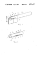
- FIG. 1 is a perspective view of a cigarette including a filter rod, the apparatus of the present invention being capable of manufacturing the filter rod;
- FIG. 2 is a perspective view of a filter tow from which the representative filter rod of FIG. 1 is made, the apparatus of the present invention being capable of manufacturing the filter tow;
- FIG. 3 is a side view of an apparatus embodying the present invention in a groove forming position
- FIG. 4 is a side view of a portion of the apparatus enclosed by the phantom circle 4 in FIG. 3 illustrating a dwell position.
- FIG. 5 is a cross-sectional view of the apparatus of FIG. 3 as viewed in the direction of arrows 5--5 in FIG. 3.
- Novel cigarette filters 8 of the type illustrated in FIG. 1 comprise a generally cylindrically shaped filter rod 10 fabricated of an air and smoke permeable material and a circumscribing wrapper 12 fabricated of an air and smoke impermeable material.
- the wrapper 12 extends longitudinally of the filter rod 10 from end 14 of the filter rod to the other end 16 thereof so that the filter rod ends 14 and 16 are in mutual flowthrough relationship.
- the filter 8 includes a plurality of grooves 18 formed in the wrapper 12 and embedded into the filter rod 10. Each of the grooves 18 is open, as designated by the number 20, at the mouth end 16 of the filter rod 10 and extends therefrom in a generally longitudinal direction of the filter rod 10 for a distance less than the length of the filter rod 10.
- the grooves 18 are illustrated as being four in number, and equally spaced from each other about the circumference of the filter rod 10.
- the filter rod 10 is attached to a tobacco column 23 by means of an air permeable tipping material 24 which circumscribes the filter rod and overlaps a portion of the tobacco column 23 in a manner known in the art to form a filtered cigarette.
- the tipping material is shown in a partially unwrapped position to more clearly show details of the wrapped filter rod.
- individual filter rods 10 are manufactured from a filter tow 26.
- the filter tow 26 is of a generally cylindrical shape and is as long as a preselected number of filter rods 10.
- the filter tow 26 is formed with longitudinally extending grooves 18A, each of which is twice as long as a groove 18 in the filter rod 10.
- the filter rod 26 is severed, generally transversely to the longitudinal centerline of the filter tow 26, at intervals corresponding to the desired filter rod 10 length, into individual filter rods 10. As illustrated, the filter tow 26 is severed at location (denoted by the dashed line "A") at the transverse centerline of the double length grooves 18A.
- two individual filter rods 10 are produced by severing the filter tow 26 at the dashed line "A".
- FIGS. 3 and 4 show a device, generally denoted as the numeral 28, for making grooves 18 in the filter rod 10 of FIG. 1.
- the following discussion will speak to forming double length grooves 18A in the filter tow 26, but it should be clearly understood that the apparatus 28 could just as readily be used to form grooves 18 in individual filter rods 10 essentially without modification.
- the groove making apparatus 28 comprises an endless conveyor means, generally denoted as the numeral 30 which has a generally horizontal top flight 32.
- Filter tow holding means generally denoted by the numeral 34, are associated with the endless conveyor means 30 for holding the filter tows 26 at predetermined spaced apart intervals along the horizontal top flight 32 of the endless conveyor means 30.
- Grooving means generally denoted as the numeral 36, located between the ends of the horizontal top flight 32 of the endless conveyor means 30 form grooves in the filter tows 26 located on the top horizontal conveyor flight 32.
- the endless conveyor means 30 comprises a pair of endless chain conveyor devices 38 and 40 located in spaced apart, side-by-side relationship.
- the endless chain conveyor 38 has a head sprocket 42 and a tail sprocket 44 and similarly, the endless chain conveyor 40 has a head sprocket 46 and a tail sprocket 48.
- the head sprockets 42 and 46 are mounted to a common shaft 50, and the tail sprockets 44 and 48 are mounted to a common shaft 52.
- the endless chain conveyor device 38 has a top horizontal flight 32A and the endless chain conveyor device 40 has a top horizontal flight 32B.
- the top horizontal flights 32A and 32B are in spaced apart, generally parallel relationship with the space therebetween being less than the length of a filter tow 26.
- the filter tow holding means 34 associated with the endless conveyor means 30 includes a plurality of pockets 54 formed in the endless chains of each of the endless chain conveyors devices 38 and 40.
- the pockets 54 are at spaced intervals along the entire length or loop of the conveyor chains of the chain conveyors 38 and 40.
- the number of pockets 54 in the endless chain of the endless chain conveyor device 38 is equal to the number of pockets 54 in the endless chain conveyor device 40.
- Each pocket 54 in the endless chain conveyor device 40 moving in the horizontal top flight 32A is in alignment with a different one of the pockets 54 in the endless chain of the endless chain conveyor device 40 moving in the horizontal top flight 32B across the space between the horizontal top flights 32A and 32B.
- the grooving means 36 is illustrated as including a plurality of pairs 56 of articulated grooving fingers 58 arranged in two rows 60 and 62 generally along the horizontal top flight 32 of the endless conveyor means 30.
- the first row 60 includes a plurality of pairs 56 of articulated fingers 58 located generally between and above the top horizontal flights 32A and 32B of the endless chain conveyor devices 38 and 40, respectively, at predetermined spaced apart intervals therealong.
- the second row 62 includes a plurality of pairs 56 of articulated fingers 58 located generally between and below the top horizontal flights 32A and 32B of the endless chain conveyor devices 38 and 40, respectively, at predetermined spaced apart intervals therealong.
- each pair 56 of articulated grooving fingers 58 in the first row 60 is generally in alignment with a different one of the pairs 56 of articulated grooving fingers 58 in the second row 62.
- the interval between adjacent pairs 56 of articulated grooving fingers 58 in the row 60 and in the row 62 is generally equal to the interval between adjacent filter tow receiving pockets 54 in the chain of the endless chain device 38 and the endless chain device 40.
- Each finger 58 of each pair 56 has a groove forming blade 64 affixed to its distal end or tip.
- Each groove forming blade 64 has substantially the same length and width dimensions as the grooves 18A to be formed in the peripheral surface of the filter tow 26.
- the groove forming blade 64 is adapted to be embedded into the peripheral surface of the filter tow 26 as the fingers 58 of each pair 56 move toward each other, thus, forming a groove 18A in the filter tow 26.
- the groove forming fingers 58 of each pair 56 include a compression spring 59 therebetween which biases the fingers 58 of each pair 56 to pivot away from each other.
- the groove forming blades 64 be heated by, for example, electrical resistance heating means if the material of the filter tow 26 has such a high modulus of elasticity that it will not otherwise take a permanent set when the groove forming blades 64 are implanted in the peripheral surface of the filter rod 26.
- the apparatus 28 further includes means, generally denoted as the numeral 66, for activating the pairs 60 of fingers 58 between a groove forming position (illustrated in FIG. 3) and a dwell position (illustrated in FIG. 4).
- a groove forming position illustrated in FIG. 3
- a dwell position illustrated in FIG. 4
- the distal ends of the fingers 58 of each pair 56 are moved toward each other to a position whereat the groove forming blades 64 at the distal ends of the fingers 58 are embedded in the peripheral surface of the filter tow 26.
- the dwell position the distal ends of the fingers 58 of each pair 56 are moved away from each other to a position whereat the groove forming blades 64 at the distal ends of the fingers 58 are retracted from the filter tow 26.
- the finger activating means comprises an upper platen 68 and a lower platen 70.
- the upper platen 68 is located in general parallel relationship to and above the top conveyor chain flights 32A and 32B.
- the lower platen 70 is located in general parallel relationship to and below the top conveyor chain flights 32A and 32B.
- the upper and lower platens 68 and 70 are moved for movement in a generally vertical direction toward and away from each other as indicated by the arrows in FIGS. 3 and 4, respectively.
- a plurality of sleeve members 72 are attached to the upper and lower platens 68 and 70 for movement therewith.
- a plurality of sleeve members 72 are attached to the upper platen 68 at spaced apart intervals corresponding to the interval between adjacent pairs 56 of fingers 58 in the first row 60, a plurality of sleeve members 72 are attached to the lower platen 70 at spaced apart intervals corresponding to the interval between adjacent pairs 56 of fingers 58 in the second row 62.
- Each one of the sleeve members 72 on the upper platen 68 is in alignment with a different one of the pairs 56 of articulated fingers 58 in the first row 60
- each one of the sleeve members 72 on the lower platen 70 is in alignment with a different one of the pairs 56 of the articulated fingers 58 in the second row 62.
- each of the sleeve members 72 moves over the proximal end of the pairs 56 of fingers 58 aligned therewith.
- the interior wall surface of the sleeve member 72 contacts and slides along each finger 58 forcing the fingers 58 to pivot about their hinged proximal ends toward each other moving the distal ends of the fingers 58 toward each other and causing the groove forming blades 64 attached to the distal ends to embed into the periphery of the filter tow 26 and form grooves 18A therein.
- each of the sleeve members 72 moves to a position away from the proximal end of the pair 56 of fingers 58 aligned therewith such that the interior wall surface of the sleeve member 72 disengages from contact with the fingers 58.
- the spring 59 between the fingers 58 of a pair 56 forces the fingers 58 to pivot about their hinged proximal end away from each other moving the distal ends of the fingers 58 away from each other and causing the groove forming blade 64 attached to the distal ends to retract from the filter tow 26.
- the apparatus 28 also includes loading means 74 for depositing a filter tow to be grooved in successive pockets 54 of the top horizontal flights 32A and 32B of the chains of the endless chain conveyor devices 38 and 40 as the pockets successively pass over the tail sprockets 44 and 48 at one end of the apparatus 28.
- the loading means comprises a hopper 76 located with its open discharge end located over the top horizontal flights 32A and 32B next to the tail sprockets 44 and 48.
- the endless chain conveyor devices 38 and 40 move through the apparatus 28 until all of the pockets 54 of the top horizontal flights 32A and 32B of the pair of endless chain conveyor devices contain filter tows 26 to be grooved.
- the endless conveyor devices 38 and 40 are stopped with each set of aligned pockets 54 of the chains of endless chain conveyor devices 38 and 40 in alignment with a different pair 56 of grooving fingers 58 in the first row 60 and with a different pair 56 of grooving fingers 58 in the second row 62.
- the endless conveyor devices 38 and 40 While the endless conveyor devices 38 and 40 are in the dwell mode, the upper and lower platens 68 and 70 are activated to move toward each other causing the sleeve members 72 to slide over aligned pairs 56 of grooving fingers 58, thus, forcing the fingers 58 of each pair 56 toward each other embedding the groove forming blades 64 attached to the distal ends of the fingers 58 into the filter tows 26 aligned with the finger pairs 56.
- the upper and lower platens 68 and 70 are then activated to move away from each other moving the sleeve members 72 away from the proximal ends of the pairs 56 of grooving fingers 58 allowing the fingers 58 of each pair 56 to move away from each other under the influence of the spring means 59, thus, extracting the grooving blades 64 from the filter tow 26.
- the endless chain conveyor devices 38 and 40 again are caused to move and exit the apparatus at the end thereof whereat the head sprockets 42 and 46 are located. As the endless chain conveyor devices 38 and 40 pass over the head sprockets 42 and 46, the filter tows 26 fall out of the pockets 54 by gravity.
- grooved filter tows 26 After the grooved filter tows 26 exit the apparatus 28, they are conveyed to another work station (not shown) where they are severed into individual filter rods 10 as discussed above.
- the means for starting and stopping the endless conveyor devices 38 and 40, and for activating the upper and lower platens 68 and 70 in timed sequence therewith are well known to the art and will, therefore, not be discussed in detail.
- Such means include, for example, pneumatic or hydraulic cylinders with solenoid valves and limit switches, motor driven rack and pinion arrangements, and other means known to the art.
- filter rod is used in a generic sense in the appended claims to mean either individual filter rods 10 or filter tow 26 from which individual filter rods 10 are cut after the apparatus 28 of the present invention has formed grooves therein.
Landscapes
- Cigarettes, Filters, And Manufacturing Of Filters (AREA)
Abstract
Description
Claims (10)
Priority Applications (1)
| Application Number | Priority Date | Filing Date | Title |
|---|---|---|---|
| US06/631,961 US4533427A (en) | 1984-07-18 | 1984-07-18 | Device for making grooves in cigarette filters |
Applications Claiming Priority (1)
| Application Number | Priority Date | Filing Date | Title |
|---|---|---|---|
| US06/631,961 US4533427A (en) | 1984-07-18 | 1984-07-18 | Device for making grooves in cigarette filters |
Publications (1)
| Publication Number | Publication Date |
|---|---|
| US4533427A true US4533427A (en) | 1985-08-06 |
Family
ID=24533495
Family Applications (1)
| Application Number | Title | Priority Date | Filing Date |
|---|---|---|---|
| US06/631,961 Expired - Fee Related US4533427A (en) | 1984-07-18 | 1984-07-18 | Device for making grooves in cigarette filters |
Country Status (1)
| Country | Link |
|---|---|
| US (1) | US4533427A (en) |
Cited By (2)
| Publication number | Priority date | Publication date | Assignee | Title |
|---|---|---|---|---|
| US5198245A (en) * | 1989-03-02 | 1993-03-30 | Nestec S.A. | Apparatus for the manufacture of extruded cakes |
| US5248513A (en) * | 1989-03-02 | 1993-09-28 | Nestec, S.A. | Process to deform surfaces of extruded materials |
Citations (6)
| Publication number | Priority date | Publication date | Assignee | Title |
|---|---|---|---|---|
| US2703047A (en) * | 1952-07-12 | 1955-03-01 | Scherer Corp R P | Machine for branding capsules |
| US3026792A (en) * | 1959-10-05 | 1962-03-27 | Pfizer & Co C | Apparatus for branding uniformlyshaped articles |
| US4075936A (en) * | 1975-10-31 | 1978-02-28 | American Filtrona Corporation | Method and apparatus for making tobacco smoke filter |
| US4324540A (en) * | 1980-07-11 | 1982-04-13 | Brown & Williamson Tobacco Corporation | Apparatus for making grooves in tobacco smoke filters |
| US4436517A (en) * | 1976-10-05 | 1984-03-13 | Baumgartner Papiers S.A. | Apparatus for making transverse flow cigarette filters |
| US4480982A (en) * | 1983-02-07 | 1984-11-06 | Brown & Williamson Tobacco Corporation | Apparatus for making grooves in cigarette filters |
-
1984
- 1984-07-18 US US06/631,961 patent/US4533427A/en not_active Expired - Fee Related
Patent Citations (6)
| Publication number | Priority date | Publication date | Assignee | Title |
|---|---|---|---|---|
| US2703047A (en) * | 1952-07-12 | 1955-03-01 | Scherer Corp R P | Machine for branding capsules |
| US3026792A (en) * | 1959-10-05 | 1962-03-27 | Pfizer & Co C | Apparatus for branding uniformlyshaped articles |
| US4075936A (en) * | 1975-10-31 | 1978-02-28 | American Filtrona Corporation | Method and apparatus for making tobacco smoke filter |
| US4436517A (en) * | 1976-10-05 | 1984-03-13 | Baumgartner Papiers S.A. | Apparatus for making transverse flow cigarette filters |
| US4324540A (en) * | 1980-07-11 | 1982-04-13 | Brown & Williamson Tobacco Corporation | Apparatus for making grooves in tobacco smoke filters |
| US4480982A (en) * | 1983-02-07 | 1984-11-06 | Brown & Williamson Tobacco Corporation | Apparatus for making grooves in cigarette filters |
Cited By (2)
| Publication number | Priority date | Publication date | Assignee | Title |
|---|---|---|---|---|
| US5198245A (en) * | 1989-03-02 | 1993-03-30 | Nestec S.A. | Apparatus for the manufacture of extruded cakes |
| US5248513A (en) * | 1989-03-02 | 1993-09-28 | Nestec, S.A. | Process to deform surfaces of extruded materials |
Similar Documents
| Publication | Publication Date | Title |
|---|---|---|
| EP2696708B9 (en) | Conveying rod-like articles in the tobacco-processing industry | |
| US2952105A (en) | Wrapping device | |
| EP1943909B1 (en) | Demand and transfer of a rod-shaped article in the tobacco industry | |
| PL196669B1 (en) | Device for combining groups of filter segments for producing multi-segment filters of the tobacco industry, and trough drum | |
| GB1589489A (en) | Manufacture of filter cigarettes | |
| US2882970A (en) | Laminated filter tip | |
| EP1547477B1 (en) | A method and a device for making filters for tobacco products | |
| DE102010043474A1 (en) | Method and device for loading objects into a filter rod of the tobacco processing industry | |
| CN110228713A (en) | The conveying cylinder of tobacco | |
| US4533427A (en) | Device for making grooves in cigarette filters | |
| US6302113B1 (en) | Apparatus for making filter cigarettes | |
| GB1371046A (en) | Manufacture of cigarettes | |
| US4480982A (en) | Apparatus for making grooves in cigarette filters | |
| US4514249A (en) | Device for making grooves in cigarette filters | |
| US3245414A (en) | Method of manufacturing filter tip cigarettes and the like | |
| US4547253A (en) | Device for making grooves in cigarette filters | |
| US4883449A (en) | Device for making grooves in cigarette filters | |
| US4211055A (en) | Machine for feeding, cutting, spacing and accumulating articles | |
| US20060052226A1 (en) | Injection of a medium into a filter segment | |
| US4714083A (en) | Making of multi-element smoking article rod | |
| US4517046A (en) | Device for making grooves in cigarette filters | |
| FI68162B (en) | ANORDING FOR FORMING AV CHANNEL AND PERIPHERAL FILTER ELEMENT | |
| DE3723001A1 (en) | DEVICE FOR CONVERSING BLOCK-SHAPED ARTICLE GROUPS OF THE TOBACCO-PROCESSING INDUSTRY | |
| US4290518A (en) | Filter attachment machines | |
| US4536149A (en) | Apparatus for making grooves in cigarette filters |
Legal Events
| Date | Code | Title | Description |
|---|---|---|---|
| AS | Assignment |
Owner name: BROWN & WILLIAMSON TOBACCO CORPORATION LOUISVILLE, Free format text: ASSIGNMENT OF ASSIGNORS INTEREST.;ASSIGNORS:REED, STEVEN P.;NASLUND, ERIK I.;REEL/FRAME:004287/0939 Effective date: 19840330 Owner name: BROWN & WILLIAMSON TOBACCO CORPORATION,KENTUCKY Free format text: ASSIGNMENT OF ASSIGNORS INTEREST;ASSIGNORS:REED, STEVEN P.;NASLUND, ERIK I.;REEL/FRAME:004287/0939 Effective date: 19840330 |
|
| FEPP | Fee payment procedure |
Free format text: PAYOR NUMBER ASSIGNED (ORIGINAL EVENT CODE: ASPN); ENTITY STATUS OF PATENT OWNER: LARGE ENTITY |
|
| FPAY | Fee payment |
Year of fee payment: 4 |
|
| FPAY | Fee payment |
Year of fee payment: 8 |
|
| REMI | Maintenance fee reminder mailed | ||
| LAPS | Lapse for failure to pay maintenance fees | ||
| FP | Lapsed due to failure to pay maintenance fee |
Effective date: 19970806 |
|
| STCH | Information on status: patent discontinuation |
Free format text: PATENT EXPIRED DUE TO NONPAYMENT OF MAINTENANCE FEES UNDER 37 CFR 1.362 |