US4533375A - Cryogenic air separation with cold argon recycle - Google Patents
Cryogenic air separation with cold argon recycle Download PDFInfo
- Publication number
- US4533375A US4533375A US06/522,516 US52251683A US4533375A US 4533375 A US4533375 A US 4533375A US 52251683 A US52251683 A US 52251683A US 4533375 A US4533375 A US 4533375A
- Authority
- US
- United States
- Prior art keywords
- argon
- column
- rectifier
- oxygen
- liquid
- Prior art date
- Legal status (The legal status is an assumption and is not a legal conclusion. Google has not performed a legal analysis and makes no representation as to the accuracy of the status listed.)
- Expired - Fee Related
Links
- XKRFYHLGVUSROY-UHFFFAOYSA-N Argon Chemical compound [Ar] XKRFYHLGVUSROY-UHFFFAOYSA-N 0.000 title claims abstract description 248
- 229910052786 argon Inorganic materials 0.000 title claims abstract description 124
- 238000000926 separation method Methods 0.000 title claims abstract description 15
- QVGXLLKOCUKJST-UHFFFAOYSA-N atomic oxygen Chemical compound [O] QVGXLLKOCUKJST-UHFFFAOYSA-N 0.000 claims abstract description 53
- 239000001301 oxygen Substances 0.000 claims abstract description 53
- 229910052760 oxygen Inorganic materials 0.000 claims abstract description 53
- 238000010992 reflux Methods 0.000 claims abstract description 26
- MYMOFIZGZYHOMD-UHFFFAOYSA-N Dioxygen Chemical compound O=O MYMOFIZGZYHOMD-UHFFFAOYSA-N 0.000 claims abstract description 25
- 238000009835 boiling Methods 0.000 claims abstract description 7
- IJGRMHOSHXDMSA-UHFFFAOYSA-N Atomic nitrogen Chemical compound N#N IJGRMHOSHXDMSA-UHFFFAOYSA-N 0.000 claims description 72
- 239000007788 liquid Substances 0.000 claims description 37
- 229910052757 nitrogen Inorganic materials 0.000 claims description 33
- 238000004821 distillation Methods 0.000 claims description 16
- 238000000034 method Methods 0.000 claims description 13
- 230000008569 process Effects 0.000 claims description 10
- 238000012546 transfer Methods 0.000 claims description 9
- 230000009977 dual effect Effects 0.000 claims description 7
- 238000002347 injection Methods 0.000 claims description 7
- 239000007924 injection Substances 0.000 claims description 7
- 229910001873 dinitrogen Inorganic materials 0.000 claims description 6
- 239000007789 gas Substances 0.000 claims description 6
- 239000006200 vaporizer Substances 0.000 claims description 6
- 230000006872 improvement Effects 0.000 claims description 5
- QJGQUHMNIGDVPM-UHFFFAOYSA-N nitrogen group Chemical group [N] QJGQUHMNIGDVPM-UHFFFAOYSA-N 0.000 claims description 3
- 238000005086 pumping Methods 0.000 claims description 3
- 238000004064 recycling Methods 0.000 claims description 2
- 230000008016 vaporization Effects 0.000 claims 3
- 238000011084 recovery Methods 0.000 abstract description 8
- 230000008901 benefit Effects 0.000 abstract description 5
- 238000005057 refrigeration Methods 0.000 description 11
- 238000007906 compression Methods 0.000 description 5
- 230000006835 compression Effects 0.000 description 5
- 230000001174 ascending effect Effects 0.000 description 3
- 238000004519 manufacturing process Methods 0.000 description 3
- 230000003247 decreasing effect Effects 0.000 description 2
- 230000009467 reduction Effects 0.000 description 2
- 239000012808 vapor phase Substances 0.000 description 2
- VVTSZOCINPYFDP-UHFFFAOYSA-N [O].[Ar] Chemical compound [O].[Ar] VVTSZOCINPYFDP-UHFFFAOYSA-N 0.000 description 1
- 230000009471 action Effects 0.000 description 1
- 230000008859 change Effects 0.000 description 1
- 238000010276 construction Methods 0.000 description 1
- 239000000356 contaminant Substances 0.000 description 1
- 238000013461 design Methods 0.000 description 1
- 238000005265 energy consumption Methods 0.000 description 1
- 238000005516 engineering process Methods 0.000 description 1
- 238000005194 fractionation Methods 0.000 description 1
- 238000010348 incorporation Methods 0.000 description 1
- 238000009434 installation Methods 0.000 description 1
- 229910052743 krypton Inorganic materials 0.000 description 1
- DNNSSWSSYDEUBZ-UHFFFAOYSA-N krypton atom Chemical compound [Kr] DNNSSWSSYDEUBZ-UHFFFAOYSA-N 0.000 description 1
- 239000007791 liquid phase Substances 0.000 description 1
- 239000000203 mixture Substances 0.000 description 1
- 238000012545 processing Methods 0.000 description 1
- 238000000746 purification Methods 0.000 description 1
- 230000001172 regenerating effect Effects 0.000 description 1
- 238000005406 washing Methods 0.000 description 1
- 239000002699 waste material Substances 0.000 description 1
- 229910052724 xenon Inorganic materials 0.000 description 1
- FHNFHKCVQCLJFQ-UHFFFAOYSA-N xenon atom Chemical compound [Xe] FHNFHKCVQCLJFQ-UHFFFAOYSA-N 0.000 description 1
Images


Classifications
-
- F—MECHANICAL ENGINEERING; LIGHTING; HEATING; WEAPONS; BLASTING
- F25—REFRIGERATION OR COOLING; COMBINED HEATING AND REFRIGERATION SYSTEMS; HEAT PUMP SYSTEMS; MANUFACTURE OR STORAGE OF ICE; LIQUEFACTION SOLIDIFICATION OF GASES
- F25J—LIQUEFACTION, SOLIDIFICATION OR SEPARATION OF GASES OR GASEOUS OR LIQUEFIED GASEOUS MIXTURES BY PRESSURE AND COLD TREATMENT OR BY BRINGING THEM INTO THE SUPERCRITICAL STATE
- F25J3/00—Processes or apparatus for separating the constituents of gaseous or liquefied gaseous mixtures involving the use of liquefaction or solidification
- F25J3/02—Processes or apparatus for separating the constituents of gaseous or liquefied gaseous mixtures involving the use of liquefaction or solidification by rectification, i.e. by continuous interchange of heat and material between a vapour stream and a liquid stream
- F25J3/04—Processes or apparatus for separating the constituents of gaseous or liquefied gaseous mixtures involving the use of liquefaction or solidification by rectification, i.e. by continuous interchange of heat and material between a vapour stream and a liquid stream for air
- F25J3/04406—Processes or apparatus for separating the constituents of gaseous or liquefied gaseous mixtures involving the use of liquefaction or solidification by rectification, i.e. by continuous interchange of heat and material between a vapour stream and a liquid stream for air using a dual pressure main column system
- F25J3/04412—Processes or apparatus for separating the constituents of gaseous or liquefied gaseous mixtures involving the use of liquefaction or solidification by rectification, i.e. by continuous interchange of heat and material between a vapour stream and a liquid stream for air using a dual pressure main column system in a classical double column flowsheet, i.e. with thermal coupling by a main reboiler-condenser in the bottom of low pressure respectively top of high pressure column
-
- F—MECHANICAL ENGINEERING; LIGHTING; HEATING; WEAPONS; BLASTING
- F25—REFRIGERATION OR COOLING; COMBINED HEATING AND REFRIGERATION SYSTEMS; HEAT PUMP SYSTEMS; MANUFACTURE OR STORAGE OF ICE; LIQUEFACTION SOLIDIFICATION OF GASES
- F25J—LIQUEFACTION, SOLIDIFICATION OR SEPARATION OF GASES OR GASEOUS OR LIQUEFIED GASEOUS MIXTURES BY PRESSURE AND COLD TREATMENT OR BY BRINGING THEM INTO THE SUPERCRITICAL STATE
- F25J3/00—Processes or apparatus for separating the constituents of gaseous or liquefied gaseous mixtures involving the use of liquefaction or solidification
- F25J3/02—Processes or apparatus for separating the constituents of gaseous or liquefied gaseous mixtures involving the use of liquefaction or solidification by rectification, i.e. by continuous interchange of heat and material between a vapour stream and a liquid stream
- F25J3/04—Processes or apparatus for separating the constituents of gaseous or liquefied gaseous mixtures involving the use of liquefaction or solidification by rectification, i.e. by continuous interchange of heat and material between a vapour stream and a liquid stream for air
- F25J3/04006—Providing pressurised feed air or process streams within or from the air fractionation unit
- F25J3/04048—Providing pressurised feed air or process streams within or from the air fractionation unit by compression of cold gaseous streams, e.g. intermediate or oxygen enriched (waste) streams
- F25J3/04072—Providing pressurised feed air or process streams within or from the air fractionation unit by compression of cold gaseous streams, e.g. intermediate or oxygen enriched (waste) streams of argon or argon enriched stream
-
- F—MECHANICAL ENGINEERING; LIGHTING; HEATING; WEAPONS; BLASTING
- F25—REFRIGERATION OR COOLING; COMBINED HEATING AND REFRIGERATION SYSTEMS; HEAT PUMP SYSTEMS; MANUFACTURE OR STORAGE OF ICE; LIQUEFACTION SOLIDIFICATION OF GASES
- F25J—LIQUEFACTION, SOLIDIFICATION OR SEPARATION OF GASES OR GASEOUS OR LIQUEFIED GASEOUS MIXTURES BY PRESSURE AND COLD TREATMENT OR BY BRINGING THEM INTO THE SUPERCRITICAL STATE
- F25J3/00—Processes or apparatus for separating the constituents of gaseous or liquefied gaseous mixtures involving the use of liquefaction or solidification
- F25J3/02—Processes or apparatus for separating the constituents of gaseous or liquefied gaseous mixtures involving the use of liquefaction or solidification by rectification, i.e. by continuous interchange of heat and material between a vapour stream and a liquid stream
- F25J3/04—Processes or apparatus for separating the constituents of gaseous or liquefied gaseous mixtures involving the use of liquefaction or solidification by rectification, i.e. by continuous interchange of heat and material between a vapour stream and a liquid stream for air
- F25J3/04006—Providing pressurised feed air or process streams within or from the air fractionation unit
- F25J3/04078—Providing pressurised feed air or process streams within or from the air fractionation unit providing pressurized products by liquid compression and vaporisation with cold recovery, i.e. so-called internal compression
- F25J3/0409—Providing pressurised feed air or process streams within or from the air fractionation unit providing pressurized products by liquid compression and vaporisation with cold recovery, i.e. so-called internal compression of oxygen
-
- F—MECHANICAL ENGINEERING; LIGHTING; HEATING; WEAPONS; BLASTING
- F25—REFRIGERATION OR COOLING; COMBINED HEATING AND REFRIGERATION SYSTEMS; HEAT PUMP SYSTEMS; MANUFACTURE OR STORAGE OF ICE; LIQUEFACTION SOLIDIFICATION OF GASES
- F25J—LIQUEFACTION, SOLIDIFICATION OR SEPARATION OF GASES OR GASEOUS OR LIQUEFIED GASEOUS MIXTURES BY PRESSURE AND COLD TREATMENT OR BY BRINGING THEM INTO THE SUPERCRITICAL STATE
- F25J3/00—Processes or apparatus for separating the constituents of gaseous or liquefied gaseous mixtures involving the use of liquefaction or solidification
- F25J3/02—Processes or apparatus for separating the constituents of gaseous or liquefied gaseous mixtures involving the use of liquefaction or solidification by rectification, i.e. by continuous interchange of heat and material between a vapour stream and a liquid stream
- F25J3/04—Processes or apparatus for separating the constituents of gaseous or liquefied gaseous mixtures involving the use of liquefaction or solidification by rectification, i.e. by continuous interchange of heat and material between a vapour stream and a liquid stream for air
- F25J3/04151—Purification and (pre-)cooling of the feed air; recuperative heat-exchange with product streams
- F25J3/04187—Cooling of the purified feed air by recuperative heat-exchange; Heat-exchange with product streams
- F25J3/04193—Division of the main heat exchange line in consecutive sections having different functions
- F25J3/04206—Division of the main heat exchange line in consecutive sections having different functions including a so-called "auxiliary vaporiser" for vaporising and producing a gaseous product
- F25J3/04212—Division of the main heat exchange line in consecutive sections having different functions including a so-called "auxiliary vaporiser" for vaporising and producing a gaseous product and simultaneously condensing vapor from a column serving as reflux within the or another column
-
- F—MECHANICAL ENGINEERING; LIGHTING; HEATING; WEAPONS; BLASTING
- F25—REFRIGERATION OR COOLING; COMBINED HEATING AND REFRIGERATION SYSTEMS; HEAT PUMP SYSTEMS; MANUFACTURE OR STORAGE OF ICE; LIQUEFACTION SOLIDIFICATION OF GASES
- F25J—LIQUEFACTION, SOLIDIFICATION OR SEPARATION OF GASES OR GASEOUS OR LIQUEFIED GASEOUS MIXTURES BY PRESSURE AND COLD TREATMENT OR BY BRINGING THEM INTO THE SUPERCRITICAL STATE
- F25J3/00—Processes or apparatus for separating the constituents of gaseous or liquefied gaseous mixtures involving the use of liquefaction or solidification
- F25J3/02—Processes or apparatus for separating the constituents of gaseous or liquefied gaseous mixtures involving the use of liquefaction or solidification by rectification, i.e. by continuous interchange of heat and material between a vapour stream and a liquid stream
- F25J3/04—Processes or apparatus for separating the constituents of gaseous or liquefied gaseous mixtures involving the use of liquefaction or solidification by rectification, i.e. by continuous interchange of heat and material between a vapour stream and a liquid stream for air
- F25J3/04248—Generation of cold for compensating heat leaks or liquid production, e.g. by Joule-Thompson expansion
- F25J3/04284—Generation of cold for compensating heat leaks or liquid production, e.g. by Joule-Thompson expansion using internal refrigeration by open-loop gas work expansion, e.g. of intermediate or oxygen enriched (waste-)streams
- F25J3/0429—Generation of cold for compensating heat leaks or liquid production, e.g. by Joule-Thompson expansion using internal refrigeration by open-loop gas work expansion, e.g. of intermediate or oxygen enriched (waste-)streams of feed air, e.g. used as waste or product air or expanded into an auxiliary column
- F25J3/04296—Claude expansion, i.e. expanded into the main or high pressure column
-
- F—MECHANICAL ENGINEERING; LIGHTING; HEATING; WEAPONS; BLASTING
- F25—REFRIGERATION OR COOLING; COMBINED HEATING AND REFRIGERATION SYSTEMS; HEAT PUMP SYSTEMS; MANUFACTURE OR STORAGE OF ICE; LIQUEFACTION SOLIDIFICATION OF GASES
- F25J—LIQUEFACTION, SOLIDIFICATION OR SEPARATION OF GASES OR GASEOUS OR LIQUEFIED GASEOUS MIXTURES BY PRESSURE AND COLD TREATMENT OR BY BRINGING THEM INTO THE SUPERCRITICAL STATE
- F25J3/00—Processes or apparatus for separating the constituents of gaseous or liquefied gaseous mixtures involving the use of liquefaction or solidification
- F25J3/02—Processes or apparatus for separating the constituents of gaseous or liquefied gaseous mixtures involving the use of liquefaction or solidification by rectification, i.e. by continuous interchange of heat and material between a vapour stream and a liquid stream
- F25J3/04—Processes or apparatus for separating the constituents of gaseous or liquefied gaseous mixtures involving the use of liquefaction or solidification by rectification, i.e. by continuous interchange of heat and material between a vapour stream and a liquid stream for air
- F25J3/04248—Generation of cold for compensating heat leaks or liquid production, e.g. by Joule-Thompson expansion
- F25J3/04284—Generation of cold for compensating heat leaks or liquid production, e.g. by Joule-Thompson expansion using internal refrigeration by open-loop gas work expansion, e.g. of intermediate or oxygen enriched (waste-)streams
- F25J3/04309—Generation of cold for compensating heat leaks or liquid production, e.g. by Joule-Thompson expansion using internal refrigeration by open-loop gas work expansion, e.g. of intermediate or oxygen enriched (waste-)streams of nitrogen
-
- F—MECHANICAL ENGINEERING; LIGHTING; HEATING; WEAPONS; BLASTING
- F25—REFRIGERATION OR COOLING; COMBINED HEATING AND REFRIGERATION SYSTEMS; HEAT PUMP SYSTEMS; MANUFACTURE OR STORAGE OF ICE; LIQUEFACTION SOLIDIFICATION OF GASES
- F25J—LIQUEFACTION, SOLIDIFICATION OR SEPARATION OF GASES OR GASEOUS OR LIQUEFIED GASEOUS MIXTURES BY PRESSURE AND COLD TREATMENT OR BY BRINGING THEM INTO THE SUPERCRITICAL STATE
- F25J3/00—Processes or apparatus for separating the constituents of gaseous or liquefied gaseous mixtures involving the use of liquefaction or solidification
- F25J3/02—Processes or apparatus for separating the constituents of gaseous or liquefied gaseous mixtures involving the use of liquefaction or solidification by rectification, i.e. by continuous interchange of heat and material between a vapour stream and a liquid stream
- F25J3/04—Processes or apparatus for separating the constituents of gaseous or liquefied gaseous mixtures involving the use of liquefaction or solidification by rectification, i.e. by continuous interchange of heat and material between a vapour stream and a liquid stream for air
- F25J3/04248—Generation of cold for compensating heat leaks or liquid production, e.g. by Joule-Thompson expansion
- F25J3/04333—Generation of cold for compensating heat leaks or liquid production, e.g. by Joule-Thompson expansion using quasi-closed loop internal vapor compression refrigeration cycles, e.g. of intermediate or oxygen enriched (waste-)streams
- F25J3/04369—Generation of cold for compensating heat leaks or liquid production, e.g. by Joule-Thompson expansion using quasi-closed loop internal vapor compression refrigeration cycles, e.g. of intermediate or oxygen enriched (waste-)streams of argon or argon enriched stream
-
- F—MECHANICAL ENGINEERING; LIGHTING; HEATING; WEAPONS; BLASTING
- F25—REFRIGERATION OR COOLING; COMBINED HEATING AND REFRIGERATION SYSTEMS; HEAT PUMP SYSTEMS; MANUFACTURE OR STORAGE OF ICE; LIQUEFACTION SOLIDIFICATION OF GASES
- F25J—LIQUEFACTION, SOLIDIFICATION OR SEPARATION OF GASES OR GASEOUS OR LIQUEFIED GASEOUS MIXTURES BY PRESSURE AND COLD TREATMENT OR BY BRINGING THEM INTO THE SUPERCRITICAL STATE
- F25J3/00—Processes or apparatus for separating the constituents of gaseous or liquefied gaseous mixtures involving the use of liquefaction or solidification
- F25J3/02—Processes or apparatus for separating the constituents of gaseous or liquefied gaseous mixtures involving the use of liquefaction or solidification by rectification, i.e. by continuous interchange of heat and material between a vapour stream and a liquid stream
- F25J3/04—Processes or apparatus for separating the constituents of gaseous or liquefied gaseous mixtures involving the use of liquefaction or solidification by rectification, i.e. by continuous interchange of heat and material between a vapour stream and a liquid stream for air
- F25J3/04248—Generation of cold for compensating heat leaks or liquid production, e.g. by Joule-Thompson expansion
- F25J3/04375—Details relating to the work expansion, e.g. process parameter etc.
- F25J3/04393—Details relating to the work expansion, e.g. process parameter etc. using multiple or multistage gas work expansion
-
- F—MECHANICAL ENGINEERING; LIGHTING; HEATING; WEAPONS; BLASTING
- F25—REFRIGERATION OR COOLING; COMBINED HEATING AND REFRIGERATION SYSTEMS; HEAT PUMP SYSTEMS; MANUFACTURE OR STORAGE OF ICE; LIQUEFACTION SOLIDIFICATION OF GASES
- F25J—LIQUEFACTION, SOLIDIFICATION OR SEPARATION OF GASES OR GASEOUS OR LIQUEFIED GASEOUS MIXTURES BY PRESSURE AND COLD TREATMENT OR BY BRINGING THEM INTO THE SUPERCRITICAL STATE
- F25J3/00—Processes or apparatus for separating the constituents of gaseous or liquefied gaseous mixtures involving the use of liquefaction or solidification
- F25J3/02—Processes or apparatus for separating the constituents of gaseous or liquefied gaseous mixtures involving the use of liquefaction or solidification by rectification, i.e. by continuous interchange of heat and material between a vapour stream and a liquid stream
- F25J3/04—Processes or apparatus for separating the constituents of gaseous or liquefied gaseous mixtures involving the use of liquefaction or solidification by rectification, i.e. by continuous interchange of heat and material between a vapour stream and a liquid stream for air
- F25J3/04436—Processes or apparatus for separating the constituents of gaseous or liquefied gaseous mixtures involving the use of liquefaction or solidification by rectification, i.e. by continuous interchange of heat and material between a vapour stream and a liquid stream for air using at least a triple pressure main column system
- F25J3/04454—Processes or apparatus for separating the constituents of gaseous or liquefied gaseous mixtures involving the use of liquefaction or solidification by rectification, i.e. by continuous interchange of heat and material between a vapour stream and a liquid stream for air using at least a triple pressure main column system a main column system not otherwise provided, e.g. serially coupling of columns or more than three pressure levels
-
- F—MECHANICAL ENGINEERING; LIGHTING; HEATING; WEAPONS; BLASTING
- F25—REFRIGERATION OR COOLING; COMBINED HEATING AND REFRIGERATION SYSTEMS; HEAT PUMP SYSTEMS; MANUFACTURE OR STORAGE OF ICE; LIQUEFACTION SOLIDIFICATION OF GASES
- F25J—LIQUEFACTION, SOLIDIFICATION OR SEPARATION OF GASES OR GASEOUS OR LIQUEFIED GASEOUS MIXTURES BY PRESSURE AND COLD TREATMENT OR BY BRINGING THEM INTO THE SUPERCRITICAL STATE
- F25J3/00—Processes or apparatus for separating the constituents of gaseous or liquefied gaseous mixtures involving the use of liquefaction or solidification
- F25J3/02—Processes or apparatus for separating the constituents of gaseous or liquefied gaseous mixtures involving the use of liquefaction or solidification by rectification, i.e. by continuous interchange of heat and material between a vapour stream and a liquid stream
- F25J3/04—Processes or apparatus for separating the constituents of gaseous or liquefied gaseous mixtures involving the use of liquefaction or solidification by rectification, i.e. by continuous interchange of heat and material between a vapour stream and a liquid stream for air
- F25J3/04624—Processes or apparatus for separating the constituents of gaseous or liquefied gaseous mixtures involving the use of liquefaction or solidification by rectification, i.e. by continuous interchange of heat and material between a vapour stream and a liquid stream for air using integrated mass and heat exchange, so-called non-adiabatic rectification, e.g. dephlegmator, reflux exchanger
- F25J3/0463—Simultaneously between rectifying and stripping sections, i.e. double dephlegmator
-
- F—MECHANICAL ENGINEERING; LIGHTING; HEATING; WEAPONS; BLASTING
- F25—REFRIGERATION OR COOLING; COMBINED HEATING AND REFRIGERATION SYSTEMS; HEAT PUMP SYSTEMS; MANUFACTURE OR STORAGE OF ICE; LIQUEFACTION SOLIDIFICATION OF GASES
- F25J—LIQUEFACTION, SOLIDIFICATION OR SEPARATION OF GASES OR GASEOUS OR LIQUEFIED GASEOUS MIXTURES BY PRESSURE AND COLD TREATMENT OR BY BRINGING THEM INTO THE SUPERCRITICAL STATE
- F25J3/00—Processes or apparatus for separating the constituents of gaseous or liquefied gaseous mixtures involving the use of liquefaction or solidification
- F25J3/02—Processes or apparatus for separating the constituents of gaseous or liquefied gaseous mixtures involving the use of liquefaction or solidification by rectification, i.e. by continuous interchange of heat and material between a vapour stream and a liquid stream
- F25J3/04—Processes or apparatus for separating the constituents of gaseous or liquefied gaseous mixtures involving the use of liquefaction or solidification by rectification, i.e. by continuous interchange of heat and material between a vapour stream and a liquid stream for air
- F25J3/04642—Recovering noble gases from air
- F25J3/04648—Recovering noble gases from air argon
- F25J3/04654—Producing crude argon in a crude argon column
- F25J3/04666—Producing crude argon in a crude argon column as a parallel working rectification column of the low pressure column in a dual pressure main column system
-
- F—MECHANICAL ENGINEERING; LIGHTING; HEATING; WEAPONS; BLASTING
- F25—REFRIGERATION OR COOLING; COMBINED HEATING AND REFRIGERATION SYSTEMS; HEAT PUMP SYSTEMS; MANUFACTURE OR STORAGE OF ICE; LIQUEFACTION SOLIDIFICATION OF GASES
- F25J—LIQUEFACTION, SOLIDIFICATION OR SEPARATION OF GASES OR GASEOUS OR LIQUEFIED GASEOUS MIXTURES BY PRESSURE AND COLD TREATMENT OR BY BRINGING THEM INTO THE SUPERCRITICAL STATE
- F25J3/00—Processes or apparatus for separating the constituents of gaseous or liquefied gaseous mixtures involving the use of liquefaction or solidification
- F25J3/02—Processes or apparatus for separating the constituents of gaseous or liquefied gaseous mixtures involving the use of liquefaction or solidification by rectification, i.e. by continuous interchange of heat and material between a vapour stream and a liquid stream
- F25J3/04—Processes or apparatus for separating the constituents of gaseous or liquefied gaseous mixtures involving the use of liquefaction or solidification by rectification, i.e. by continuous interchange of heat and material between a vapour stream and a liquid stream for air
- F25J3/04642—Recovering noble gases from air
- F25J3/04648—Recovering noble gases from air argon
- F25J3/04654—Producing crude argon in a crude argon column
- F25J3/04709—Producing crude argon in a crude argon column as an auxiliary column system in at least a dual pressure main column system
- F25J3/04715—The auxiliary column system simultaneously produces oxygen
-
- F—MECHANICAL ENGINEERING; LIGHTING; HEATING; WEAPONS; BLASTING
- F25—REFRIGERATION OR COOLING; COMBINED HEATING AND REFRIGERATION SYSTEMS; HEAT PUMP SYSTEMS; MANUFACTURE OR STORAGE OF ICE; LIQUEFACTION SOLIDIFICATION OF GASES
- F25J—LIQUEFACTION, SOLIDIFICATION OR SEPARATION OF GASES OR GASEOUS OR LIQUEFIED GASEOUS MIXTURES BY PRESSURE AND COLD TREATMENT OR BY BRINGING THEM INTO THE SUPERCRITICAL STATE
- F25J3/00—Processes or apparatus for separating the constituents of gaseous or liquefied gaseous mixtures involving the use of liquefaction or solidification
- F25J3/02—Processes or apparatus for separating the constituents of gaseous or liquefied gaseous mixtures involving the use of liquefaction or solidification by rectification, i.e. by continuous interchange of heat and material between a vapour stream and a liquid stream
- F25J3/04—Processes or apparatus for separating the constituents of gaseous or liquefied gaseous mixtures involving the use of liquefaction or solidification by rectification, i.e. by continuous interchange of heat and material between a vapour stream and a liquid stream for air
- F25J3/04763—Start-up or control of the process; Details of the apparatus used
- F25J3/04769—Operation, control and regulation of the process; Instrumentation within the process
- F25J3/04854—Safety aspects of operation
- F25J3/0486—Safety aspects of operation of vaporisers for oxygen enriched liquids, e.g. purging of liquids
-
- F—MECHANICAL ENGINEERING; LIGHTING; HEATING; WEAPONS; BLASTING
- F25—REFRIGERATION OR COOLING; COMBINED HEATING AND REFRIGERATION SYSTEMS; HEAT PUMP SYSTEMS; MANUFACTURE OR STORAGE OF ICE; LIQUEFACTION SOLIDIFICATION OF GASES
- F25J—LIQUEFACTION, SOLIDIFICATION OR SEPARATION OF GASES OR GASEOUS OR LIQUEFIED GASEOUS MIXTURES BY PRESSURE AND COLD TREATMENT OR BY BRINGING THEM INTO THE SUPERCRITICAL STATE
- F25J2200/00—Processes or apparatus using separation by rectification
- F25J2200/08—Processes or apparatus using separation by rectification in a triple pressure main column system
-
- F—MECHANICAL ENGINEERING; LIGHTING; HEATING; WEAPONS; BLASTING
- F25—REFRIGERATION OR COOLING; COMBINED HEATING AND REFRIGERATION SYSTEMS; HEAT PUMP SYSTEMS; MANUFACTURE OR STORAGE OF ICE; LIQUEFACTION SOLIDIFICATION OF GASES
- F25J—LIQUEFACTION, SOLIDIFICATION OR SEPARATION OF GASES OR GASEOUS OR LIQUEFIED GASEOUS MIXTURES BY PRESSURE AND COLD TREATMENT OR BY BRINGING THEM INTO THE SUPERCRITICAL STATE
- F25J2200/00—Processes or apparatus using separation by rectification
- F25J2200/10—Processes or apparatus using separation by rectification in a quadruple, or more, column or pressure system
-
- F—MECHANICAL ENGINEERING; LIGHTING; HEATING; WEAPONS; BLASTING
- F25—REFRIGERATION OR COOLING; COMBINED HEATING AND REFRIGERATION SYSTEMS; HEAT PUMP SYSTEMS; MANUFACTURE OR STORAGE OF ICE; LIQUEFACTION SOLIDIFICATION OF GASES
- F25J—LIQUEFACTION, SOLIDIFICATION OR SEPARATION OF GASES OR GASEOUS OR LIQUEFIED GASEOUS MIXTURES BY PRESSURE AND COLD TREATMENT OR BY BRINGING THEM INTO THE SUPERCRITICAL STATE
- F25J2200/00—Processes or apparatus using separation by rectification
- F25J2200/50—Processes or apparatus using separation by rectification using multiple (re-)boiler-condensers at different heights of the column
- F25J2200/52—Processes or apparatus using separation by rectification using multiple (re-)boiler-condensers at different heights of the column in the high pressure column of a double pressure main column system
-
- F—MECHANICAL ENGINEERING; LIGHTING; HEATING; WEAPONS; BLASTING
- F25—REFRIGERATION OR COOLING; COMBINED HEATING AND REFRIGERATION SYSTEMS; HEAT PUMP SYSTEMS; MANUFACTURE OR STORAGE OF ICE; LIQUEFACTION SOLIDIFICATION OF GASES
- F25J—LIQUEFACTION, SOLIDIFICATION OR SEPARATION OF GASES OR GASEOUS OR LIQUEFIED GASEOUS MIXTURES BY PRESSURE AND COLD TREATMENT OR BY BRINGING THEM INTO THE SUPERCRITICAL STATE
- F25J2200/00—Processes or apparatus using separation by rectification
- F25J2200/50—Processes or apparatus using separation by rectification using multiple (re-)boiler-condensers at different heights of the column
- F25J2200/54—Processes or apparatus using separation by rectification using multiple (re-)boiler-condensers at different heights of the column in the low pressure column of a double pressure main column system
-
- F—MECHANICAL ENGINEERING; LIGHTING; HEATING; WEAPONS; BLASTING
- F25—REFRIGERATION OR COOLING; COMBINED HEATING AND REFRIGERATION SYSTEMS; HEAT PUMP SYSTEMS; MANUFACTURE OR STORAGE OF ICE; LIQUEFACTION SOLIDIFICATION OF GASES
- F25J—LIQUEFACTION, SOLIDIFICATION OR SEPARATION OF GASES OR GASEOUS OR LIQUEFIED GASEOUS MIXTURES BY PRESSURE AND COLD TREATMENT OR BY BRINGING THEM INTO THE SUPERCRITICAL STATE
- F25J2200/00—Processes or apparatus using separation by rectification
- F25J2200/90—Details relating to column internals, e.g. structured packing, gas or liquid distribution
-
- F—MECHANICAL ENGINEERING; LIGHTING; HEATING; WEAPONS; BLASTING
- F25—REFRIGERATION OR COOLING; COMBINED HEATING AND REFRIGERATION SYSTEMS; HEAT PUMP SYSTEMS; MANUFACTURE OR STORAGE OF ICE; LIQUEFACTION SOLIDIFICATION OF GASES
- F25J—LIQUEFACTION, SOLIDIFICATION OR SEPARATION OF GASES OR GASEOUS OR LIQUEFIED GASEOUS MIXTURES BY PRESSURE AND COLD TREATMENT OR BY BRINGING THEM INTO THE SUPERCRITICAL STATE
- F25J2205/00—Processes or apparatus using other separation and/or other processing means
- F25J2205/02—Processes or apparatus using other separation and/or other processing means using simple phase separation in a vessel or drum
-
- F—MECHANICAL ENGINEERING; LIGHTING; HEATING; WEAPONS; BLASTING
- F25—REFRIGERATION OR COOLING; COMBINED HEATING AND REFRIGERATION SYSTEMS; HEAT PUMP SYSTEMS; MANUFACTURE OR STORAGE OF ICE; LIQUEFACTION SOLIDIFICATION OF GASES
- F25J—LIQUEFACTION, SOLIDIFICATION OR SEPARATION OF GASES OR GASEOUS OR LIQUEFIED GASEOUS MIXTURES BY PRESSURE AND COLD TREATMENT OR BY BRINGING THEM INTO THE SUPERCRITICAL STATE
- F25J2205/00—Processes or apparatus using other separation and/or other processing means
- F25J2205/60—Processes or apparatus using other separation and/or other processing means using adsorption on solid adsorbents, e.g. by temperature-swing adsorption [TSA] at the hot or cold end
-
- F—MECHANICAL ENGINEERING; LIGHTING; HEATING; WEAPONS; BLASTING
- F25—REFRIGERATION OR COOLING; COMBINED HEATING AND REFRIGERATION SYSTEMS; HEAT PUMP SYSTEMS; MANUFACTURE OR STORAGE OF ICE; LIQUEFACTION SOLIDIFICATION OF GASES
- F25J—LIQUEFACTION, SOLIDIFICATION OR SEPARATION OF GASES OR GASEOUS OR LIQUEFIED GASEOUS MIXTURES BY PRESSURE AND COLD TREATMENT OR BY BRINGING THEM INTO THE SUPERCRITICAL STATE
- F25J2235/00—Processes or apparatus involving steps for increasing the pressure or for conveying of liquid process streams
- F25J2235/02—Processes or apparatus involving steps for increasing the pressure or for conveying of liquid process streams using a pump in general or hydrostatic pressure increase
-
- F—MECHANICAL ENGINEERING; LIGHTING; HEATING; WEAPONS; BLASTING
- F25—REFRIGERATION OR COOLING; COMBINED HEATING AND REFRIGERATION SYSTEMS; HEAT PUMP SYSTEMS; MANUFACTURE OR STORAGE OF ICE; LIQUEFACTION SOLIDIFICATION OF GASES
- F25J—LIQUEFACTION, SOLIDIFICATION OR SEPARATION OF GASES OR GASEOUS OR LIQUEFIED GASEOUS MIXTURES BY PRESSURE AND COLD TREATMENT OR BY BRINGING THEM INTO THE SUPERCRITICAL STATE
- F25J2240/00—Processes or apparatus involving steps for expanding of process streams
- F25J2240/60—Expansion by ejector or injector, e.g. "Gasstrahlpumpe", "venturi mixing", "jet pumps"
-
- F—MECHANICAL ENGINEERING; LIGHTING; HEATING; WEAPONS; BLASTING
- F25—REFRIGERATION OR COOLING; COMBINED HEATING AND REFRIGERATION SYSTEMS; HEAT PUMP SYSTEMS; MANUFACTURE OR STORAGE OF ICE; LIQUEFACTION SOLIDIFICATION OF GASES
- F25J—LIQUEFACTION, SOLIDIFICATION OR SEPARATION OF GASES OR GASEOUS OR LIQUEFIED GASEOUS MIXTURES BY PRESSURE AND COLD TREATMENT OR BY BRINGING THEM INTO THE SUPERCRITICAL STATE
- F25J2245/00—Processes or apparatus involving steps for recycling of process streams
- F25J2245/02—Recycle of a stream in general, e.g. a by-pass stream
-
- F—MECHANICAL ENGINEERING; LIGHTING; HEATING; WEAPONS; BLASTING
- F25—REFRIGERATION OR COOLING; COMBINED HEATING AND REFRIGERATION SYSTEMS; HEAT PUMP SYSTEMS; MANUFACTURE OR STORAGE OF ICE; LIQUEFACTION SOLIDIFICATION OF GASES
- F25J—LIQUEFACTION, SOLIDIFICATION OR SEPARATION OF GASES OR GASEOUS OR LIQUEFIED GASEOUS MIXTURES BY PRESSURE AND COLD TREATMENT OR BY BRINGING THEM INTO THE SUPERCRITICAL STATE
- F25J2250/00—Details related to the use of reboiler-condensers
- F25J2250/20—Boiler-condenser with multiple exchanger cores in parallel or with multiple re-boiling or condensing streams
-
- F—MECHANICAL ENGINEERING; LIGHTING; HEATING; WEAPONS; BLASTING
- F25—REFRIGERATION OR COOLING; COMBINED HEATING AND REFRIGERATION SYSTEMS; HEAT PUMP SYSTEMS; MANUFACTURE OR STORAGE OF ICE; LIQUEFACTION SOLIDIFICATION OF GASES
- F25J—LIQUEFACTION, SOLIDIFICATION OR SEPARATION OF GASES OR GASEOUS OR LIQUEFIED GASEOUS MIXTURES BY PRESSURE AND COLD TREATMENT OR BY BRINGING THEM INTO THE SUPERCRITICAL STATE
- F25J2250/00—Details related to the use of reboiler-condensers
- F25J2250/30—External or auxiliary boiler-condenser in general, e.g. without a specified fluid or one fluid is not a primary air component or an intermediate fluid
- F25J2250/50—One fluid being oxygen
-
- F—MECHANICAL ENGINEERING; LIGHTING; HEATING; WEAPONS; BLASTING
- F25—REFRIGERATION OR COOLING; COMBINED HEATING AND REFRIGERATION SYSTEMS; HEAT PUMP SYSTEMS; MANUFACTURE OR STORAGE OF ICE; LIQUEFACTION SOLIDIFICATION OF GASES
- F25J—LIQUEFACTION, SOLIDIFICATION OR SEPARATION OF GASES OR GASEOUS OR LIQUEFIED GASEOUS MIXTURES BY PRESSURE AND COLD TREATMENT OR BY BRINGING THEM INTO THE SUPERCRITICAL STATE
- F25J2250/00—Details related to the use of reboiler-condensers
- F25J2250/30—External or auxiliary boiler-condenser in general, e.g. without a specified fluid or one fluid is not a primary air component or an intermediate fluid
- F25J2250/58—One fluid being argon or crude argon
-
- Y—GENERAL TAGGING OF NEW TECHNOLOGICAL DEVELOPMENTS; GENERAL TAGGING OF CROSS-SECTIONAL TECHNOLOGIES SPANNING OVER SEVERAL SECTIONS OF THE IPC; TECHNICAL SUBJECTS COVERED BY FORMER USPC CROSS-REFERENCE ART COLLECTIONS [XRACs] AND DIGESTS
- Y10—TECHNICAL SUBJECTS COVERED BY FORMER USPC
- Y10S—TECHNICAL SUBJECTS COVERED BY FORMER USPC CROSS-REFERENCE ART COLLECTIONS [XRACs] AND DIGESTS
- Y10S62/00—Refrigeration
- Y10S62/923—Inert gas
- Y10S62/924—Argon
Definitions
- the invention comprises process and apparatus for increasing the efficiency, the oxygen purity, the oxygen pressure, or the argon recovery, singly or in combination, in cryogenic distillative air separation processes.
- U.S. Pat. Nos. 3,277,655, 3,327,489, 4,372,765, and 4,254,629 all disclose low energy flowsheets involving lower than normal HP rectifier pressures, and all result in limited purity oxygen (below about 98%) due to reduced reboil available in the argon stripping section of the LP column.
- the first three reflect a dual pressure (two column) arrangement, whereas the latter reflects alternatively a triple pressure arrangement with split air supply pressure or a quadruple pressure column arrangement with single supply pressure.
- U.S. Pat. No. 3,688,513 partly avoids the oxygen purity limitation of low energy triple pressure column flowsheets by incorporating an argon stripper at the bottom of the medium pressure column in addition to the one at the bottom of the LP column.
- the argon stripping duty is divided between the two strippers, and thus much of the reboil diverted from the LP column to the MP column is still effective in stripping argon.
- This configuration also incorporates liquid recycle from the LP column overhead back to the MP column, in order to remove argon from the LP column.
- This configuration has the disadvantages of requiring two separate argon strippers; not recovering argon; having MP column bottom product hotter than desirable (which requires higher HP column pressure) due to need to eliminate nitrogen from the LP column feed and to the extra pressure drop in the MP argon stripper; and generating oxygen at lower than usual pressure.
- an argon recycle compressor external to the cold box which is used to produce pressurized oxygen by latent heat exchange of the compressed argon with pumped liquid oxygen.
- the condensed argon is subsequently used to reflux the argon rectifying section of the low pressure column. (That section is frequently referred to as the "auxiliary column").
- All of these configurations incorporate an argon recycle compressor which is external to the cold box, and hence entail substantial pressure drops of the argon when exiting and reentering the cold box, plus some temperature gain due to heat exchanger inefficiency. This, coupled with the fact that the argon compressor is compressing a warm gas rather than a cold one, results in greatly increased argon compression energy requirements.
- the circulating argon gas is preferably no more than about 30% oxygen to preclude need for special oxygen tolerant construction of the compressor. These configurations are reported to be useful for O 2 delivery pressures up to about 40 atmospheres, but are claimed to require more power than external compression of oxygen by O 2 compressors. (H. Springmann, Linde Reports on Science and Technology 31/1980, "The Production of High-Pressure Oxygen")
- thermocompressors in cryogenic air distillation processes whereby the pressure letdown of liquid nitrogen from the HP rectifier is the motive power for compressing some nitrogen gas to a pressure above the LP column pressure.
- U.S. Pat. Nos. 4,091,633 and 4,325,719 are two versions of this technique.
- a process and apparatus incorporating a low pressure distillation column with both argon stripping and argon rectifying sections wherein an argon recycle compressor internal to the cold box compresses vapor from the argon rectifier and discharges it to a reboiler/condenser so as to reboil liquid oxygen bottom product from the bottom of the argon stripper, thereby increasing the reboil rate through both the argon stripper and the argon rectifier.
- the condensed argon is direct injected into the argon rectifier overhead as reflux.
- the argon recycle compressor only requires a compression ratio of approximately two due to its location in the cold box. Thus its power requirement and resulting refrigeration requirement are very small.
- additional refrigeration is required, either by increasing flow through an existing expander or by incorporating an additional expander. For every mole of nitrogen gas from the HP rectifier overhead that can be expanded, more than one mole of argon can be recycled, resulting in more reboil through the argon stripper than the condensing of the nitrogen would otherwise have caused.
- supply air can be expanded.
- the recycle compressor can be directly driven by one of the expanders, thus decreasing cost.
- two expanders are provided, they can operate at different temperatures so as to equalize the temperature differential across and hence maximize the effectiveness of the main heat exchangers which separate the cold box from the outside world.
- the disclosed invention has general utility in many different air separation plants and circumstances.
- one of the greatest advantages it provides is in low energy triple pressure flowsheets for producing medium to high purity oxygen.
- medium to high purity oxygen delivery pressures up to about 10 atmospheres at high efficiency and without either an oxygen compressor or an external argon recycle compressor.
- the five figures illustrate several of the many configurations which will benefit by incorporation of the disclosed recycling or heat pumping of an argon-rich stream within the cold box.
- the first four are various versions of the high efficiency triple pressure configuration incorporating LP to MP latent heat exchange.
- the low pressure column has both an argon rectifier and a nitrogen rectifier.
- nitrogen recycle from the LP column to the MP column is via a combination of liquid and thermocompressed vapor, and reflux is via latent heat exchange with boiling nitrogen.
- the argon recycle is merely to increase O 2 purity and argon recovery, as O 2 delivery pressure is not increased.
- N 2 removal from the LP column N 2 rectifier is by a combination of recycle thermocompression, and vacuum compression, and reflux is via direct injection of liquid nitrogen.
- the argon recycle not only increases O 2 purity, but makes possible a pumped LOX configuration for pressurizing product oxygen from a split supply pressure.
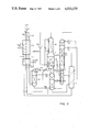
- FIG. 3 also incorporates split supply pressure and LOX pumping for producing pressurized high purity oxygen. It differs from FIG. 2 in that no N 2 rectification section is present in the LP column, since the MP column bottom liquid contains less than about 1% N 2 , and in incorporating a second refrigeration expander.
- FIG. 4 illustrates one way non-adiabatic distillation can be incorporated in a triple pressure flowsheet incorporating cold argon recycle.
- FIG. 5 illustrates the application of cold argon recycle to a conventional dual pressure column, as for example in a backfit installation.
- main air compressor 1 air is compressed in main air compressor 1, cleaned and dried in cleaner-drier 2, and cooled in main heat exchanger 3 which may be regenerative, reversing, or other known types. It enters the bottom of high pressure rectifier 4.
- Nitrogen gas from the rectifier overhead provides reboil to LP column 5 and MP column 6 via reboiler/reflux condensers 7 and 8 respectively, via transfer of latent heat.
- Another part of the nitrogen gas provides refrigeration by expansion in expander 9.
- a midlength location of the HP rectifier also transfers latent heat to the MP column via reboiler/reflux condenser 10.
- Bottom liquid (oxygen enriched liquid air) from the HP rectifier is supplied the MP column via sensible heat exchanger 11 and means for pressure reduction 12, in this instance a thermocompressor.
- Overhead liquid nitrogen is supplied as direct injection reflux to MP column 6 via sensible heat exchanger 13, and is supplied to reflux LP column 5 overhead by latent heat exchange in evaporator/reflux condenser 14 via control valve 15.
- Bottom liquid from MP column 6, which consists mainly of oxygen and argon and contains no more than about 10% nitrogen, is routed through separator 16 and means for one way flow control 17, e.g., a check valve or pump, and is introduced into LP column 5.
- the residual nitrogen content of that stream is rectified to overhead in the N 2 rectification section 18 of LP column 5.
- thermocompressor 12 It is removed from the LP column and recycled to the MP column partly in vapor phase by thermocompressor 12 and one way valve 19, and partly in liquid phase by means for one way flow control 20, e.g., a check valve or pump.
- the liquid oxygen-argon mixture washing down the LP column is stripped of much of the argon in the argon stripper section 21 of LP column 5, by the action of ascending vapor from reboiler 7 and reboiler/condenser 22.
- the ascending vapor divides between the N 2 rectification section 18, the argon rectification section 23, and reboiler/reflux condenser 24, which transfers latent heat from an LP column midlength or intermediate location to an MP column midlength or intermediate location.
- the fraction of vapor entering and ascending argon rectifier 23 is washed by liquid reflux so as to remove much of the oxygen, leaving an argon stream of approximately 70% or higher purity overhead. That stream is compressed by compressor 25 to a pressure sufficient to condense against boiling oxygen in reboiler/condenser 22.
- the resulting liquid argon condensate is returned to the argon rectifier as direct injection reflux via means for one way flow control 26, e.g., a check valve or pump. Part of the argon may be withdrawn as product or for further purification. Gaseous oxygen bottom product from LP column 5 and gaseous nitrogen overhead from MP column 6 and heat exchanger 14 are withdrawn from the cold box via heat exchanger 3.
- the HP rectifier pressure will normally be about 4 ATA.
- the MP column overhead pressure will be about 1.5 ATA, i.e., just sufficient to spontaneously exhaust the gaseous N 2 to ambient.
- the LP column will operate approximately at or below atmospheric pressure, and hence cannot discharge products at design flow rates to atmospheric pressure without mechanical assist. There will normally be up to about 10% N 2 in the MP column liquid bottom product, and typically 1 to 5%.
- FIG. 2 incorporates an elevated pressure rectifier 27 and liquid oxygen pump 28, enabling pressurized high purity oxygen to be produced directly without requirement for an oxygen compressor.
- Liquid oxygen bottom product from LP column 5 argon strip section 21
- LOX pump 28 cleaned of trace contaminants in adsorber 29, and supplied to vaporizer/reflux condenser 30, where it is gasified at pressure.
- Part of the supply air is further compressed to an elevated pressure and supplied to the bottom of elevated pressure rectifier 27.
- the elevated pressure required is approximately three times the desired O 2 delivery pressure, depending on the temperature differential of exchanger 30.
- an O 2 delivery pressure of 5 ATA and a 2K ⁇ T will require an elevated pressure of about 16 ATA at the compressor discharge.
- the amount of supply air compressed to elevated pressure will be between approximately 22 and 35% of the total air supplied, depending on the amount of N 2 supplied expander 31.
- Liquid N 2 and oxygen enriched liquid air from the elevated pressure rectifier are routed to the heat integrated triple pressure column 4, 5, and 6 via pressure letdown valves 32 and 33 respectively for further separation.
- the valves could alternatively be thermocompressors.
- FIG. 2 illustrates several optional features.
- An additional reboil is supplied to the bottom of MP column 6 via reboiler/condenser 34, which transfers latent heat from supply HP air (or equivalently from the bottom of the HP rectifier) to the MP column bottom liquid. This allows lower HP rectifier pressures and hence lower energy consumption.
- the nitrogen rejection from the N 2 rectification section 18 of LP column 5 is all done in vapor phase, and refluxing of that section is done by direct injection of liquid nitrogen through J-T valve 35.
- Impure nitrogen containing vapor is thermocompressed by 12 as before, and higher purity nitrogen vapor is both thermo-compressed by liquid nitrogen via one way valve 37 and thermocompressor 36, and also is vacuum compressed out of the cold box by vacuum compressor 38.
- FIG. 3 illustrates two of the above options.
- FIG. 3 the description of components 1, 3 thru 11, 17, 21 thru 30, 32, and 33 corresponds to the same numbered components described above for FIGS. 1 or 2.
- Part of the supply air from HP compressor 1 is further compressed in elevated pressure compressor 39 and cooled in the first section of main exchanger 3a.
- part of the elevated pressure supply air is expanded in expander 40 to HP supply pressure, and joins that stream entering HP rectifier 4.
- the remaining EP supply air enters EP rectifier 27.
- Processing and separation proceeds as described above, except in this case the bottom liquid from the MP column is reduced to below about 1% N 2 content, and hence a nitrogen rectification section is not necessary in the LP column.
- the LP column consists only of argon stripping section 21 and argon rectification section 23.
- Cold argon recycle compressor 25 and reboiler/condenser 22 provide reflux and reboil to both sections; whereas reboiler 7 provides reboil only to the stripper, and thence to the MP column via exchanger 24.
- An optional addition would be to provide more reflux to the argon rectification section in the conventional manner, by latent heat exchange with part of the oxygen enriched liquid bottom product from the HP column.
- the refrigeration duty is partly supplied expander 9 supplied with HP rectifier N 2 , and partly by expander 40, with the two expanders developing refrigeration at different temperature levels to equalize the temperature differential across exchangers 3 a and 3b. Since no thermocompression of N 2 vapors is required, pressure letdown devices 12 and 36 are merely J-T valves in this flowsheet.
- FIG. 4 is a simplified version of FIG. 1 in which LP column 5 doesn't require a nitrogen rectification section, and in which the HP rectifier and bottom half of the MP column plus their associated discrete latent heat exchanges have been replaced by non-adiabatic fractionation device 41 with its associated continuous latent heat exchange. Only the main features are illustrated with many heat exchangers and other equipment or connections deleted for clarity.
- FIG. 5 illustrates the application of cold argon recycle to a dual pressure column apparatus.
- the low pressure column 5 of the dual pressure apparatus contains an argon stripper section 21, argon rectification section 23, and nitrogen rectification section 18. Being a conventional configuration, the overhead nitrogen gas from the LP column exhausts spontaneously to atmosphere.
- the cold argon recycle can be applied to a single pressure column, dual pressure column, or triple pressure arrangement, indeed to any arrangement having both an argon stripper and rectifier.
- Argon vapor withdrawal from or liquid reflux to the argon rectifier is not required to be at the top, but either could be at an intermediate height also.
- Indirect heat exchange reflux may also be present in the argon rectifier.
- the pumped liquid oxygen can be vaporized against condensing compressed air rather than against condensing nitrogen from the EP rectifier.
- Both reboilers 7 and 22 function to vaporize liquid oxygen, at least part of which becomes reboil, whereas in some flowsheets some also becomes gaseous product.
- the happenstance that some or all of the gaseous oxygen from reboiler 22 may be withdrawn as product does not change its basic role of assisting reboiler 7 in supplying reboil to the LP column.
Landscapes
- Engineering & Computer Science (AREA)
- Physics & Mathematics (AREA)
- Mechanical Engineering (AREA)
- Thermal Sciences (AREA)
- General Engineering & Computer Science (AREA)
- Health & Medical Sciences (AREA)
- Emergency Medicine (AREA)
- Separation By Low-Temperature Treatments (AREA)
Abstract
The invention provides an efficient means of increasing oxygen purity and recovery and also argon recovery in cryogenic distillative air separation plants. In addition, the invention makes it possible to increase the oxygen delivery pressure from high efficiency triple pressure configurations without using an oxygen vacuum compressor. These advantages are obtained by incorporating an argon recycle compressor within the cold box, which compresses argon from an argon rectifier, causes it to condense against boiling liquid oxygen from the argon stripper, and uses the condensed argon to reflux the argon rectifier. Pressurized high purity oxygen can then be obtained using a LOX pump, plus a split supply pressure configuration in which an elevated pressure rectifier gasifies the LOX.
Description
1. Technical Field
The invention comprises process and apparatus for increasing the efficiency, the oxygen purity, the oxygen pressure, or the argon recovery, singly or in combination, in cryogenic distillative air separation processes.
2. Background Art
In conventional dual pressure air separation processes the oxygen purity is limited by the amount of reboil available to the argon stripping section of the low pressure column, and the argon recovery is limited by the amount of reboil and reflux available to the argon rectification section of the low pressure column. In high efficiency flowsheets these limitations are usually even more severe, since in order to decrease the pressure of the high pressure rectifier, some of the available reboil normally bypasses the argon stripper. The product oxygen pressure is also frequently decreased due to the lower HP rectifier pressure.
U.S. Pat. Nos. 3,277,655, 3,327,489, 4,372,765, and 4,254,629 all disclose low energy flowsheets involving lower than normal HP rectifier pressures, and all result in limited purity oxygen (below about 98%) due to reduced reboil available in the argon stripping section of the LP column. The first three reflect a dual pressure (two column) arrangement, whereas the latter reflects alternatively a triple pressure arrangement with split air supply pressure or a quadruple pressure column arrangement with single supply pressure.
U.S. Pat. No. 2,699,046 to Etienne reflects numerous triple pressure and one quadruple pressure column arrangements. Several of those arrangements also accomplish lower energy requirement at the expense of lower oxygen purity. One, FIG. 6, does not decrease separation energy but increases the purity of the nitrogen product.
U.S. Pat. No. 3,688,513 partly avoids the oxygen purity limitation of low energy triple pressure column flowsheets by incorporating an argon stripper at the bottom of the medium pressure column in addition to the one at the bottom of the LP column. The argon stripping duty is divided between the two strippers, and thus much of the reboil diverted from the LP column to the MP column is still effective in stripping argon. This configuration also incorporates liquid recycle from the LP column overhead back to the MP column, in order to remove argon from the LP column.
This configuration has the disadvantages of requiring two separate argon strippers; not recovering argon; having MP column bottom product hotter than desirable (which requires higher HP column pressure) due to need to eliminate nitrogen from the LP column feed and to the extra pressure drop in the MP argon stripper; and generating oxygen at lower than usual pressure.
U.S. application Ser. No. 501,264 filed 6/6/83 by Donald C. Erickson, which is incorporated by reference, overcomes several of the above disadvantages. A triple pressure configuration is disclosed which only requires an argon stripper at the bottom of the LP column, which allows some nitrogen content in the liquid bottom product of the MP column; which allows argon recovery; and which allows both lower energy (lower high pressure rectifier and supply air pressures) and higher O2 purity. This is done by incorporating latent heat transfer from above the LP argon stripper to a midlength location of the MP column, and also by providing a colder source of reflux to the LP column overhead, e.g., liquid N2 (either direct injection or indirect heat exchange) when necessary to reject N2 from the LP overhead. However these improvements still have the problem of yielding product oxygen at lower than normal pressures, e.g., at a vacuum. A further disclosed improvement, which further increases oxygen purity, entails withdrawing liquid oxygen from the LP column bottom and gasifying it by indirect latent heat exchange at the top of the argon stripping section--this causes an even further reduction in the oxygen production pressure.
It is known to incorporate compressor recycle of an argon stream, generally an impure argon stream, into cryogenic air separation plants for several different advantageous purposes. In U.S. Pat. Nos. 3,596,471 and 4,057,407, an argon compressor external to the cold box is used to compress argon derived from the argon rectifying section of the low pressure column, thereby increasing the reboil rate through that section. The objective of the former patent is to recover krypton and xenon, while that of the latter is to increase argon recovery and purity. In U.S. Pat. No. 3,222,878 and also in application U.S. Ser. No. 501,264 supra, an argon recycle compressor external to the cold box is described which is used to produce pressurized oxygen by latent heat exchange of the compressed argon with pumped liquid oxygen. The condensed argon is subsequently used to reflux the argon rectifying section of the low pressure column. (That section is frequently referred to as the "auxiliary column"). All of these configurations incorporate an argon recycle compressor which is external to the cold box, and hence entail substantial pressure drops of the argon when exiting and reentering the cold box, plus some temperature gain due to heat exchanger inefficiency. This, coupled with the fact that the argon compressor is compressing a warm gas rather than a cold one, results in greatly increased argon compression energy requirements. The circulating argon gas is preferably no more than about 30% oxygen to preclude need for special oxygen tolerant construction of the compressor. These configurations are reported to be useful for O2 delivery pressures up to about 40 atmospheres, but are claimed to require more power than external compression of oxygen by O2 compressors. (H. Springmann, Linde Reports on Science and Technology 31/1980, "The Production of High-Pressure Oxygen")
It is known to incorporate a split supply pressure in an air separation process to increase the delivery pressure of the product oxygen. Part of the supply air is compressed to a higher than normal pressure and then vaporized against boiling pumped liquid oxygen. U.S. Pat. Nos. 3,500,651, 3,754,406, and 4,279,631 illustrate versions of this. The Springmann article supra also describes this. An improvement to this technique, utilizing an additional higher pressure rectifier to vaporize the LOX rather than a simple reboiler/condenser, is disclosed in application Ser. No. 416,980 filed 9/13/83 by Donald C. Erickson, which is incorporated by reference.
It is known to incorporate thermocompressors in cryogenic air distillation processes whereby the pressure letdown of liquid nitrogen from the HP rectifier is the motive power for compressing some nitrogen gas to a pressure above the LP column pressure. U.S. Pat. Nos. 4,091,633 and 4,325,719 are two versions of this technique.
It is known that in distillation it is desirable to add heat (reboil) to the stripping (bottom) section of a distillation column over a range of tray heights or temperatures, and similarly for the rectifying (top) section to reject heat (i.e., add reflux) over a range of tray heights or temperatures. Several of the prior art disclosures referred to above incorporate two or more discrete exchanges of heat from the HP rectifier to the stripping section of a lower pressure column. However it is also known to conduct this heat exchange continuously over a range of tray heights. This is accomplished by "differential" or "non-adiabatic" distillation, as described in U.S. Pat. Nos. 3,508,412 and 3,563,047.
There is a need for a method of increasing the reboil rate through the argon stripping and rectifying sections of the low pressure distillation column in an air separation process without incurring the high energy penalties of an argon compressor recycle circuit with the compressor external to the cold box. This would yield several unexpected advantages, as detailed below.
A process and apparatus is provided incorporating a low pressure distillation column with both argon stripping and argon rectifying sections wherein an argon recycle compressor internal to the cold box compresses vapor from the argon rectifier and discharges it to a reboiler/condenser so as to reboil liquid oxygen bottom product from the bottom of the argon stripper, thereby increasing the reboil rate through both the argon stripper and the argon rectifier. The condensed argon is direct injected into the argon rectifier overhead as reflux.
The extra compression duty within the cold box adds to the refrigeration requirement. If there is already excess refrigeration available, no additional provision will be necessary--the argon compressor takes advantage of refrigeration which would otherwise be wasted, and as a result improves the recovery and purity of both the argon and oxygen. This could be done for example during cold weather with a plant that is designed for warm weather.
The argon recycle compressor only requires a compression ratio of approximately two due to its location in the cold box. Thus its power requirement and resulting refrigeration requirement are very small. When more argon recycle is desired than possible from waste refrigeration, additional refrigeration is required, either by increasing flow through an existing expander or by incorporating an additional expander. For every mole of nitrogen gas from the HP rectifier overhead that can be expanded, more than one mole of argon can be recycled, resulting in more reboil through the argon stripper than the condensing of the nitrogen would otherwise have caused. Alternatively supply air can be expanded. The recycle compressor can be directly driven by one of the expanders, thus decreasing cost. When two expanders are provided, they can operate at different temperatures so as to equalize the temperature differential across and hence maximize the effectiveness of the main heat exchangers which separate the cold box from the outside world.
As indicated above, the disclosed invention has general utility in many different air separation plants and circumstances. However one of the greatest advantages it provides is in low energy triple pressure flowsheets for producing medium to high purity oxygen. In those, it makes it possible to avoid the low oxygen delivery pressures that were previously characteristic. In particular, it makes possible the use of a high efficiency split supply pressure pumped LOX flowsheet, as disclosed in application No. 416,980 supra, in combination with a high efficiency triple pressure medium to high oxygen purity flowsheet as disclosed in application No. 501,264 supra. Thus it is possible to provide medium to high purity oxygen delivery pressures up to about 10 atmospheres at high efficiency and without either an oxygen compressor or an external argon recycle compressor.
The five figures illustrate several of the many configurations which will benefit by incorporation of the disclosed recycling or heat pumping of an argon-rich stream within the cold box. The first four are various versions of the high efficiency triple pressure configuration incorporating LP to MP latent heat exchange.
In FIGS. 1 and 2 the low pressure column has both an argon rectifier and a nitrogen rectifier.
In FIG. 1, nitrogen recycle from the LP column to the MP column is via a combination of liquid and thermocompressed vapor, and reflux is via latent heat exchange with boiling nitrogen. The argon recycle is merely to increase O2 purity and argon recovery, as O2 delivery pressure is not increased.
In FIG. 2 N2 removal from the LP column N2 rectifier is by a combination of recycle thermocompression, and vacuum compression, and reflux is via direct injection of liquid nitrogen. The argon recycle not only increases O2 purity, but makes possible a pumped LOX configuration for pressurizing product oxygen from a split supply pressure.
FIG. 3 also incorporates split supply pressure and LOX pumping for producing pressurized high purity oxygen. It differs from FIG. 2 in that no N2 rectification section is present in the LP column, since the MP column bottom liquid contains less than about 1% N2, and in incorporating a second refrigeration expander.
FIG. 4 illustrates one way non-adiabatic distillation can be incorporated in a triple pressure flowsheet incorporating cold argon recycle.
FIG. 5 illustrates the application of cold argon recycle to a conventional dual pressure column, as for example in a backfit installation.
Referring to FIG. 1, air is compressed in main air compressor 1, cleaned and dried in cleaner-drier 2, and cooled in main heat exchanger 3 which may be regenerative, reversing, or other known types. It enters the bottom of high pressure rectifier 4. Nitrogen gas from the rectifier overhead provides reboil to LP column 5 and MP column 6 via reboiler/reflux condensers 7 and 8 respectively, via transfer of latent heat. Another part of the nitrogen gas provides refrigeration by expansion in expander 9. A midlength location of the HP rectifier also transfers latent heat to the MP column via reboiler/reflux condenser 10. Bottom liquid (oxygen enriched liquid air) from the HP rectifier is supplied the MP column via sensible heat exchanger 11 and means for pressure reduction 12, in this instance a thermocompressor. Overhead liquid nitrogen is supplied as direct injection reflux to MP column 6 via sensible heat exchanger 13, and is supplied to reflux LP column 5 overhead by latent heat exchange in evaporator/reflux condenser 14 via control valve 15. Bottom liquid from MP column 6, which consists mainly of oxygen and argon and contains no more than about 10% nitrogen, is routed through separator 16 and means for one way flow control 17, e.g., a check valve or pump, and is introduced into LP column 5. The residual nitrogen content of that stream is rectified to overhead in the N2 rectification section 18 of LP column 5. It is removed from the LP column and recycled to the MP column partly in vapor phase by thermocompressor 12 and one way valve 19, and partly in liquid phase by means for one way flow control 20, e.g., a check valve or pump. The liquid oxygen-argon mixture washing down the LP column is stripped of much of the argon in the argon stripper section 21 of LP column 5, by the action of ascending vapor from reboiler 7 and reboiler/condenser 22. After traversing argon stripper, the ascending vapor divides between the N2 rectification section 18, the argon rectification section 23, and reboiler/reflux condenser 24, which transfers latent heat from an LP column midlength or intermediate location to an MP column midlength or intermediate location. The fraction of vapor entering and ascending argon rectifier 23 is washed by liquid reflux so as to remove much of the oxygen, leaving an argon stream of approximately 70% or higher purity overhead. That stream is compressed by compressor 25 to a pressure sufficient to condense against boiling oxygen in reboiler/condenser 22. The resulting liquid argon condensate is returned to the argon rectifier as direct injection reflux via means for one way flow control 26, e.g., a check valve or pump. Part of the argon may be withdrawn as product or for further purification. Gaseous oxygen bottom product from LP column 5 and gaseous nitrogen overhead from MP column 6 and heat exchanger 14 are withdrawn from the cold box via heat exchanger 3.
Using this flowsheet for the production of medium (>96%) to high (>98%) purity oxygen, the HP rectifier pressure will normally be about 4 ATA. The MP column overhead pressure will be about 1.5 ATA, i.e., just sufficient to spontaneously exhaust the gaseous N2 to ambient. The LP column will operate approximately at or below atmospheric pressure, and hence cannot discharge products at design flow rates to atmospheric pressure without mechanical assist. There will normally be up to about 10% N2 in the MP column liquid bottom product, and typically 1 to 5%.
In FIG. 2, components 3 thru 8, 10 thru 12, 17 thru 19, and 21 thru 26, perform functions as described above, as modified below. The main difference between FIGS. 1 and 2 is that FIG. 2 incorporates an elevated pressure rectifier 27 and liquid oxygen pump 28, enabling pressurized high purity oxygen to be produced directly without requirement for an oxygen compressor. Liquid oxygen bottom product from LP column 5 (argon strip section 21) is pressurized in LOX pump 28, cleaned of trace contaminants in adsorber 29, and supplied to vaporizer/reflux condenser 30, where it is gasified at pressure. Part of the supply air is further compressed to an elevated pressure and supplied to the bottom of elevated pressure rectifier 27. The elevated pressure required is approximately three times the desired O2 delivery pressure, depending on the temperature differential of exchanger 30. For example, an O2 delivery pressure of 5 ATA and a 2K ΔT will require an elevated pressure of about 16 ATA at the compressor discharge. The amount of supply air compressed to elevated pressure will be between approximately 22 and 35% of the total air supplied, depending on the amount of N2 supplied expander 31. Liquid N2 and oxygen enriched liquid air from the elevated pressure rectifier are routed to the heat integrated triple pressure column 4, 5, and 6 via pressure letdown valves 32 and 33 respectively for further separation. The valves could alternatively be thermocompressors.
FIG. 2 illustrates several optional features. An additional reboil is supplied to the bottom of MP column 6 via reboiler/condenser 34, which transfers latent heat from supply HP air (or equivalently from the bottom of the HP rectifier) to the MP column bottom liquid. This allows lower HP rectifier pressures and hence lower energy consumption. The nitrogen rejection from the N2 rectification section 18 of LP column 5 is all done in vapor phase, and refluxing of that section is done by direct injection of liquid nitrogen through J-T valve 35. Impure nitrogen containing vapor is thermocompressed by 12 as before, and higher purity nitrogen vapor is both thermo-compressed by liquid nitrogen via one way valve 37 and thermocompressor 36, and also is vacuum compressed out of the cold box by vacuum compressor 38.
It will be apparent that a variety of refrigeration expander options are available. Gaseous N2 from either the HP or EP rectifier overhead can be expanded. EP rectifier overhead can be expanded either to atmospheric pressure or to HP rectifier pressure. Part or all of either the HP air supply or the EP air supply can be expanded into any of the several distillation columns. FIG. 3 illustrates two of the above options.
In FIG. 3, the description of components 1, 3 thru 11, 17, 21 thru 30, 32, and 33 corresponds to the same numbered components described above for FIGS. 1 or 2. Part of the supply air from HP compressor 1 is further compressed in elevated pressure compressor 39 and cooled in the first section of main exchanger 3a. Then part of the elevated pressure supply air is expanded in expander 40 to HP supply pressure, and joins that stream entering HP rectifier 4. The remaining EP supply air enters EP rectifier 27. Processing and separation proceeds as described above, except in this case the bottom liquid from the MP column is reduced to below about 1% N2 content, and hence a nitrogen rectification section is not necessary in the LP column. The LP column consists only of argon stripping section 21 and argon rectification section 23. Cold argon recycle compressor 25 and reboiler/condenser 22 provide reflux and reboil to both sections; whereas reboiler 7 provides reboil only to the stripper, and thence to the MP column via exchanger 24. An optional addition would be to provide more reflux to the argon rectification section in the conventional manner, by latent heat exchange with part of the oxygen enriched liquid bottom product from the HP column. The refrigeration duty is partly supplied expander 9 supplied with HP rectifier N2, and partly by expander 40, with the two expanders developing refrigeration at different temperature levels to equalize the temperature differential across exchangers 3 a and 3b. Since no thermocompression of N2 vapors is required, pressure letdown devices 12 and 36 are merely J-T valves in this flowsheet.
FIG. 4 is a simplified version of FIG. 1 in which LP column 5 doesn't require a nitrogen rectification section, and in which the HP rectifier and bottom half of the MP column plus their associated discrete latent heat exchanges have been replaced by non-adiabatic fractionation device 41 with its associated continuous latent heat exchange. Only the main features are illustrated with many heat exchangers and other equipment or connections deleted for clarity. Similarly, FIG. 5 illustrates the application of cold argon recycle to a dual pressure column apparatus. The low pressure column 5 of the dual pressure apparatus contains an argon stripper section 21, argon rectification section 23, and nitrogen rectification section 18. Being a conventional configuration, the overhead nitrogen gas from the LP column exhausts spontaneously to atmosphere. Cold argon is recycled thru the stripper and argon rectifier as before, via recycle/heat pump compressor 25. Two optional features pertinent to all the flowsheets are illustrated--sensible heat exchange between compressed argon and gaseous oxygen in exchanger 42, and diversion of J-T valve expansion gas in separator 43. Clearly either of FIG. 4 or 5 could also incorporate the pumped LOX and elevated pressure rectification variations or embodiments.
It will be apparent to the artisan that many more variations or embodiments than those illustrated or described are possible within the scope of the disclosed invention, which is defined by the claims. The cold argon recycle can be applied to a single pressure column, dual pressure column, or triple pressure arrangement, indeed to any arrangement having both an argon stripper and rectifier. Argon vapor withdrawal from or liquid reflux to the argon rectifier is not required to be at the top, but either could be at an intermediate height also. Indirect heat exchange reflux may also be present in the argon rectifier. The pumped liquid oxygen can be vaporized against condensing compressed air rather than against condensing nitrogen from the EP rectifier. Both reboilers 7 and 22 function to vaporize liquid oxygen, at least part of which becomes reboil, whereas in some flowsheets some also becomes gaseous product. The happenstance that some or all of the gaseous oxygen from reboiler 22 may be withdrawn as product does not change its basic role of assisting reboiler 7 in supplying reboil to the LP column.
Claims (20)
1. In a process for separating air by cryogenic distillation comprising stripping argon from a liquid oxygen stream in an argon stripper and reducing the oxygen content of a gaseous argon stream in an argon rectifier, the improvement comprising increasing the reboil rate through the argon stripper and rectifier using a compressor internal to the cold box by:
(a) compressing gaseous argon from the argon rectifier;
(b) condensing at least part of the compressed argon by latent heat exchange with boiling oxygen from the argon stripper;
(c) reboiling the argon stripper with at least part of the evaporated oxygen from step (b);
(d) refluxing the argon rectifier with at least part of the condensed argon from step (b).
2. The process according to claim 1 wherein the argon stripper and rectifier are connected parts of the same low pressure column, wherein the refluxing is by direct injection, and comprising compressing the argon within the cold box without prior heat exchange, and comprising withdrawing part of the compressed argon.
3. The process according to claim 2 further comprising separating the air in a dual pressure distillation apparatus, wherein the argon rectifier and stripper are integral parts of the lower pressure column.
4. The process according to claim 3 further comprising additionally refluxing the argon rectifier by latent heat exchange with part of the oxygen enriched liquid air from the high pressure rectifier.
5. The process according to claim 2 further comprising separating the air in a triple pressure distillation apparatus incorporating latent heat exchange from above the argon stripper of the LP column to an intermediate height location of the MP column.
6. The process according to claim 5 further comprising removing a gas containing nitrogen from a separate nitrogen rectifying section of the LP column.
7. The process according to claim 2 further comprising supply part of the feed air at an elevated pressure, pumping liquid oxygen to a high pressure, and exchanging latent heat between the pumped liquid oxygen and at least part of the elevated pressure air.
8. The process according to claim 7 wherein the latent heat exchanging step comprises rectifying the elevated pressure air in an elevated pressure rectification column against boiling pumped liquid oxygen.
9. In a cryogenic air separation apparatus for producing medium to high purity oxygen comprising a low pressure distillation column comprising at least an argon stripper and an argon rectifier, the improvement comprising means designed, sized, and arranged for increasing the reboil rate through the stripper and rectifier while minimizing the energy requirements, including:
(a) an argon compressor which is internal to the cold box;
(b) a vapor conduit from the rectifier to the compressor;
(c) a means for vaporizing argon stripper bottom liquid by latent heat exchange with a condensing gas;
(d) a vapor conduit from the compressor to the heat exchange means;
(e) a liquid conduit to transport condensed argon from the heat exchange means to the argon rectifier reflux inlet.
10. The apparatus according to claim 9 further comprised of a means for ensuring unidirectional flow such as a pump or one-way valve disposed along the length of the liquid conduit.
11. The apparatus according to claim 9 further comprised of a liquid oxygen pump for pressurizing argon stripper bottom product oxygen liquid, and an oxygen vaporizer for vaporizing the pressurized oxygen by latent heat exchange with elevated pressure gas.
12. The apparatus according to claim 11 further comprising an elevated pressure rectifier which receives elevated pressure air at the bottom, supplies elevated pressure nitrogen gas to the oxygen vaporizer, is refluxed by part of the liquid nitrogen from oxygen vaporizer, and delivers the remaining liquid nitrogen plus oxygen enriched liquid bottom product to the remainder of the distillative air separation apparatus for further separation.
13. A triple pressure distillation apparatus for air separation comprising
a high pressure (HP) rectifier which receives at least part of the supply air;
a medium pressure (MP) distillation column which received and further distills liquid bottom product from the HP rectifier, and which is refluxed by direct injection of liquid nitrogen;
a conduit for removing nitrogen vapor from the MP column overhead;
a low pressure (LP) distillation column which receives and further purifies liquid bottom product from the MP column;
at least one means for latent heat transfer from the HP rectifier to the MP column;
a means for latent heat transfer from the Hp rectifier to the LP column;
a means for latent heat transfer from the Lp column to the MP column;
means designed, sized, and arranged for increasing the reboil rate through the LP column while minimizing the energy requirement, including an argon compressor internal to the cold box.
14. The apparatus according to claim 13 further comprised of an argon stripping section and argon rectification section in the LP column; a compressor for compressing argon-rich vapor from the argon rectifier; and a latent heat exchanger for condensing argon-rich vapor against boiling argon stripper bottom product.
15. The apparatus according to claim 14 further comprised of a liquid oxygen pump for pressurizing argon stripper liquid bottom product and a liquid oxygen vaporizer for vaporizing the pressurized liquid oxygen.
16. The apparatus according to claim 15 further comprised of an elevated pressure rectifier which receives part of the supply air, and which supplies nitrogen vapor to the oxygen vaporizer where it is condensed.
17. The apparatus according to claim 13 further comprised of a nitrogen rectification section in the LP column; and a means for recycling nitrogen containing liquid from the nitrogen rectification section to the MP column.
18. The apparatus according to claim 13 further comprised of a nitrogen rectification section in the LP column; and a means for withdrawing nitrogen containing vapor from the nitrogen rectification section.
19. The apparatus according to claim 18 wherein at least part of the vapor withdrawn from the nitrogen rectification section is thermocompressed to the MP column by at least one thermocompressor powered by liquid from the HP rectifier.
20. The apparatus according to claim 13 wherein at least two of the distillation columns are associated in indirect heat exchange relation so as to permit at least latent heat transfer between the columns through adjacent walls thereof.
Priority Applications (1)
| Application Number | Priority Date | Filing Date | Title |
|---|---|---|---|
| US06/522,516 US4533375A (en) | 1983-08-12 | 1983-08-12 | Cryogenic air separation with cold argon recycle |
Applications Claiming Priority (1)
| Application Number | Priority Date | Filing Date | Title |
|---|---|---|---|
| US06/522,516 US4533375A (en) | 1983-08-12 | 1983-08-12 | Cryogenic air separation with cold argon recycle |
Publications (1)
| Publication Number | Publication Date |
|---|---|
| US4533375A true US4533375A (en) | 1985-08-06 |
Family
ID=24081179
Family Applications (1)
| Application Number | Title | Priority Date | Filing Date |
|---|---|---|---|
| US06/522,516 Expired - Fee Related US4533375A (en) | 1983-08-12 | 1983-08-12 | Cryogenic air separation with cold argon recycle |
Country Status (1)
| Country | Link |
|---|---|
| US (1) | US4533375A (en) |
Cited By (46)
| Publication number | Priority date | Publication date | Assignee | Title |
|---|---|---|---|---|
| WO1987006329A1 (en) * | 1986-04-18 | 1987-10-22 | Erickson Donald C | Companded total condensation loxboil air distillation |
| US4715874A (en) * | 1986-09-08 | 1987-12-29 | Erickson Donald C | Retrofittable argon recovery improvement to air separation |
| US4747859A (en) * | 1986-09-12 | 1988-05-31 | The Boc Group Plc | Air separation |
| US4747860A (en) * | 1986-08-28 | 1988-05-31 | The Boc Group Plc | Air separation |
| WO1988005893A1 (en) * | 1987-02-03 | 1988-08-11 | Erickson Donald C | Companded total condensation reboil cryogenic air separation |
| US4775399A (en) * | 1987-11-17 | 1988-10-04 | Erickson Donald C | Air fractionation improvements for nitrogen production |
| US4783208A (en) * | 1986-11-24 | 1988-11-08 | The Boc Group Plc | Air separation |
| US4783209A (en) * | 1986-07-02 | 1988-11-08 | Erickson Donald C | Cryogenic air distillation with companded nitrogen refrigeration |
| WO1988009909A1 (en) * | 1987-06-02 | 1988-12-15 | Donald Erickson | Enhanced argon recovery from intermediate linboil |
| EP0299364A3 (en) * | 1987-07-09 | 1989-03-15 | Linde Aktiengesellschaft | Process and apparatus for air separation by rectification |
| US4818262A (en) * | 1985-07-15 | 1989-04-04 | L'air Liquide, Societe Anonyme Pour L'etude Et L'exploitation Des Procedes Georges Claude | Air distillation process and plant |
| US4836836A (en) * | 1987-12-14 | 1989-06-06 | Air Products And Chemicals, Inc. | Separating argon/oxygen mixtures using a structured packing |
| US4838913A (en) * | 1988-02-10 | 1989-06-13 | Union Carbide Corporation | Double column air separation process with hybrid upper column |
| US4838785A (en) * | 1988-07-05 | 1989-06-13 | Cameron Forge Company | Walking beam furnace insulation |
| US4842625A (en) * | 1988-04-29 | 1989-06-27 | Air Products And Chemicals, Inc. | Control method to maximize argon recovery from cryogenic air separation units |
| US4854954A (en) * | 1988-05-17 | 1989-08-08 | Erickson Donald C | Rectifier liquid generated intermediate reflux for subambient cascades |
| US4871382A (en) * | 1987-12-14 | 1989-10-03 | Air Products And Chemicals, Inc. | Air separation process using packed columns for oxygen and argon recovery |
| USRE34038E (en) * | 1987-12-14 | 1992-08-25 | Air Products And Chemicals, Inc. | Separating argon/oxygen mixtures using a structured packing |
| EP0527501A1 (en) * | 1991-08-14 | 1993-02-17 | Linde Aktiengesellschaft | Air rectification process and apparatus |
| US5228296A (en) * | 1992-02-27 | 1993-07-20 | Praxair Technology, Inc. | Cryogenic rectification system with argon heat pump |
| US5231837A (en) * | 1991-10-15 | 1993-08-03 | Liquid Air Engineering Corporation | Cryogenic distillation process for the production of oxygen and nitrogen |
| US5235816A (en) * | 1991-10-10 | 1993-08-17 | Praxair Technology, Inc. | Cryogenic rectification system for producing high purity oxygen |
| US5385024A (en) * | 1993-09-29 | 1995-01-31 | Praxair Technology, Inc. | Cryogenic rectification system with improved recovery |
| EP0694745A1 (en) * | 1994-07-25 | 1996-01-31 | The BOC Group plc | Air separation |
| EP0694744A1 (en) * | 1994-07-25 | 1996-01-31 | The BOC Group plc | Air separation |
| EP0733869A3 (en) * | 1995-03-21 | 1997-05-02 | Boc Group Plc | Air separation |
| EP0768504A3 (en) * | 1995-10-11 | 1998-03-04 | The BOC Group plc | Air separation |
| EP0828123A3 (en) * | 1996-09-05 | 1998-06-17 | The Boc Group Plc | Air separation |
| EP0831285A3 (en) * | 1996-09-20 | 1998-06-24 | The BOC Group plc | Air separation |
| EP0831284A3 (en) * | 1996-09-20 | 1998-07-08 | The BOC Group plc | Air separation |
| US5921108A (en) * | 1997-12-02 | 1999-07-13 | Praxair Technology, Inc. | Reflux condenser cryogenic rectification system for producing lower purity oxygen |
| US6134912A (en) * | 1999-01-27 | 2000-10-24 | Air Liquide America Corporation | Method and system for separation of a mixed gas containing oxygen and chlorine |
| EP1134526A3 (en) * | 2000-03-01 | 2002-01-16 | Air Products And Chemicals, Inc. | Process for the production of oxygen and nitrogen |
| US6397631B1 (en) | 2001-06-12 | 2002-06-04 | Air Products And Chemicals, Inc. | Air separation process |
| US20040060810A1 (en) * | 2000-11-22 | 2004-04-01 | Koichi. Asano | Method and device for separation and concentration by evaporation of mixture with separation factor of approx.1 |
| FR2930331A1 (en) * | 2008-04-22 | 2009-10-23 | Air Liquide | Cryogenic distillation air separation method, involves compressing air component enriched fluid, cooling compressed fluid in exchange line to form cold fluid, and condensing cold fluid in condenser of low pressure column of column system |
| US20160003537A1 (en) * | 2013-02-26 | 2016-01-07 | Taiyo Nippon Sanso Corporation | Air separation method and air separation apparatus |
| JP2018031544A (en) * | 2016-08-25 | 2018-03-01 | 神鋼エア・ウォーター・クライオプラント株式会社 | Method for producing oxygen gas, and device therefor |
| WO2019126927A1 (en) * | 2017-12-25 | 2019-07-04 | L'air Liquide, Societe Anonyme Pour L'etude Et L'exploitation Des Procedes Georges Claude | Single packaged air separation apparatus with reverse main heat exchanger |
| US10852061B2 (en) | 2017-05-16 | 2020-12-01 | Terrence J. Ebert | Apparatus and process for liquefying gases |
| WO2020244801A1 (en) * | 2019-06-04 | 2020-12-10 | Linde Gmbh | Method and system for low-temperature air separation |
| US11149636B2 (en) | 2019-03-01 | 2021-10-19 | Richard Alan Callahan | Turbine powered electricity generation |
| US11149634B2 (en) | 2019-03-01 | 2021-10-19 | Richard Alan Callahan | Turbine powered electricity generation |
| US11808206B2 (en) | 2022-02-24 | 2023-11-07 | Richard Alan Callahan | Tail gas recycle combined cycle power plant |
| US11994063B2 (en) | 2019-10-16 | 2024-05-28 | Richard Alan Callahan | Turbine powered electricity generation |
| EP4455588A1 (en) * | 2023-04-24 | 2024-10-30 | L'air Liquide, Societe Anonyme Pour L'etude Et L'exploitation Des Procedes Georges Claude | Process and apparatus for the separation of air by cryogenic distillation |
Citations (2)
| Publication number | Priority date | Publication date | Assignee | Title |
|---|---|---|---|---|
| US4345925A (en) * | 1980-11-26 | 1982-08-24 | Union Carbide Corporation | Process for the production of high pressure oxygen gas |
| US4384876A (en) * | 1980-08-29 | 1983-05-24 | Nippon Sanso K.K. | Process for producing krypton and Xenon |
-
1983
- 1983-08-12 US US06/522,516 patent/US4533375A/en not_active Expired - Fee Related
Patent Citations (2)
| Publication number | Priority date | Publication date | Assignee | Title |
|---|---|---|---|---|
| US4384876A (en) * | 1980-08-29 | 1983-05-24 | Nippon Sanso K.K. | Process for producing krypton and Xenon |
| US4345925A (en) * | 1980-11-26 | 1982-08-24 | Union Carbide Corporation | Process for the production of high pressure oxygen gas |
Cited By (66)
| Publication number | Priority date | Publication date | Assignee | Title |
|---|---|---|---|---|
| US4818262A (en) * | 1985-07-15 | 1989-04-04 | L'air Liquide, Societe Anonyme Pour L'etude Et L'exploitation Des Procedes Georges Claude | Air distillation process and plant |
| WO1987006329A1 (en) * | 1986-04-18 | 1987-10-22 | Erickson Donald C | Companded total condensation loxboil air distillation |
| US4817393A (en) * | 1986-04-18 | 1989-04-04 | Erickson Donald C | Companded total condensation loxboil air distillation |
| US4783209A (en) * | 1986-07-02 | 1988-11-08 | Erickson Donald C | Cryogenic air distillation with companded nitrogen refrigeration |
| US4747860A (en) * | 1986-08-28 | 1988-05-31 | The Boc Group Plc | Air separation |
| US4715874A (en) * | 1986-09-08 | 1987-12-29 | Erickson Donald C | Retrofittable argon recovery improvement to air separation |
| EP0260002A3 (en) * | 1986-09-12 | 1988-11-23 | The Boc Group Plc | Air separation |
| US4747859A (en) * | 1986-09-12 | 1988-05-31 | The Boc Group Plc | Air separation |
| US4783208A (en) * | 1986-11-24 | 1988-11-08 | The Boc Group Plc | Air separation |
| WO1988005893A1 (en) * | 1987-02-03 | 1988-08-11 | Erickson Donald C | Companded total condensation reboil cryogenic air separation |
| US4769055A (en) * | 1987-02-03 | 1988-09-06 | Erickson Donald C | Companded total condensation reboil cryogenic air separation |
| WO1988009909A1 (en) * | 1987-06-02 | 1988-12-15 | Donald Erickson | Enhanced argon recovery from intermediate linboil |
| US4832719A (en) * | 1987-06-02 | 1989-05-23 | Erickson Donald C | Enhanced argon recovery from intermediate linboil |
| EP0299364A3 (en) * | 1987-07-09 | 1989-03-15 | Linde Aktiengesellschaft | Process and apparatus for air separation by rectification |
| US4775399A (en) * | 1987-11-17 | 1988-10-04 | Erickson Donald C | Air fractionation improvements for nitrogen production |
| WO1989004942A1 (en) * | 1987-11-17 | 1989-06-01 | Erickson Donald C | Air fractionation improvements for nitrogen production |
| USRE34038E (en) * | 1987-12-14 | 1992-08-25 | Air Products And Chemicals, Inc. | Separating argon/oxygen mixtures using a structured packing |
| US4836836A (en) * | 1987-12-14 | 1989-06-06 | Air Products And Chemicals, Inc. | Separating argon/oxygen mixtures using a structured packing |
| US4871382A (en) * | 1987-12-14 | 1989-10-03 | Air Products And Chemicals, Inc. | Air separation process using packed columns for oxygen and argon recovery |
| US4838913A (en) * | 1988-02-10 | 1989-06-13 | Union Carbide Corporation | Double column air separation process with hybrid upper column |
| US4842625A (en) * | 1988-04-29 | 1989-06-27 | Air Products And Chemicals, Inc. | Control method to maximize argon recovery from cryogenic air separation units |
| US4854954A (en) * | 1988-05-17 | 1989-08-08 | Erickson Donald C | Rectifier liquid generated intermediate reflux for subambient cascades |
| US4838785A (en) * | 1988-07-05 | 1989-06-13 | Cameron Forge Company | Walking beam furnace insulation |
| EP0527501A1 (en) * | 1991-08-14 | 1993-02-17 | Linde Aktiengesellschaft | Air rectification process and apparatus |
| US5251449A (en) * | 1991-08-14 | 1993-10-12 | Linde Aktiengesellschaft | Process and apparatus for air fractionation by rectification |
| US5235816A (en) * | 1991-10-10 | 1993-08-17 | Praxair Technology, Inc. | Cryogenic rectification system for producing high purity oxygen |
| US5231837A (en) * | 1991-10-15 | 1993-08-03 | Liquid Air Engineering Corporation | Cryogenic distillation process for the production of oxygen and nitrogen |
| US5228296A (en) * | 1992-02-27 | 1993-07-20 | Praxair Technology, Inc. | Cryogenic rectification system with argon heat pump |
| EP0558082A1 (en) * | 1992-02-27 | 1993-09-01 | Praxair Technology, Inc. | Cryogenic rectification system with argon heat pump |
| US5385024A (en) * | 1993-09-29 | 1995-01-31 | Praxair Technology, Inc. | Cryogenic rectification system with improved recovery |
| US5577394A (en) * | 1994-07-25 | 1996-11-26 | The Boc Group Plc | Air separation |
| EP0694744A1 (en) * | 1994-07-25 | 1996-01-31 | The BOC Group plc | Air separation |
| EP0694745A1 (en) * | 1994-07-25 | 1996-01-31 | The BOC Group plc | Air separation |
| US5582031A (en) * | 1994-07-25 | 1996-12-10 | The Boc Group Plc | Air separation |
| EP0733869A3 (en) * | 1995-03-21 | 1997-05-02 | Boc Group Plc | Air separation |
| US5657644A (en) * | 1995-03-21 | 1997-08-19 | The Boc Group Plc | Air separation |
| EP1243883A1 (en) * | 1995-03-21 | 2002-09-25 | The BOC Group plc | Air separation |
| EP0768504A3 (en) * | 1995-10-11 | 1998-03-04 | The BOC Group plc | Air separation |
| EP0828123A3 (en) * | 1996-09-05 | 1998-06-17 | The Boc Group Plc | Air separation |
| EP0831284A3 (en) * | 1996-09-20 | 1998-07-08 | The BOC Group plc | Air separation |
| US5852940A (en) * | 1996-09-20 | 1998-12-29 | The Boc Group Plc | Air separation |
| US5878598A (en) * | 1996-09-20 | 1999-03-09 | The Boc Group Plc | Air separation |
| AU719240B2 (en) * | 1996-09-20 | 2000-05-04 | Boc Group Plc, The | Air separation |
| EP0831285A3 (en) * | 1996-09-20 | 1998-06-24 | The BOC Group plc | Air separation |
| US5921108A (en) * | 1997-12-02 | 1999-07-13 | Praxair Technology, Inc. | Reflux condenser cryogenic rectification system for producing lower purity oxygen |
| US6134912A (en) * | 1999-01-27 | 2000-10-24 | Air Liquide America Corporation | Method and system for separation of a mixed gas containing oxygen and chlorine |
| EP1134526A3 (en) * | 2000-03-01 | 2002-01-16 | Air Products And Chemicals, Inc. | Process for the production of oxygen and nitrogen |
| US20040060810A1 (en) * | 2000-11-22 | 2004-04-01 | Koichi. Asano | Method and device for separation and concentration by evaporation of mixture with separation factor of approx.1 |
| EP1338327A4 (en) * | 2000-11-22 | 2005-04-27 | METHOD AND DEVICE FOR SEPARATING AND CONCENTRATING BY EVAPORATING A MIXTURE WITH A SEPARATE FACTOR OF APPENDIX 1 | |
| US7297237B2 (en) | 2000-11-22 | 2007-11-20 | Koichi Asano | Method and device for separation and concentration by evaporation of mixture with separation factor of approx. 1 |
| US6397631B1 (en) | 2001-06-12 | 2002-06-04 | Air Products And Chemicals, Inc. | Air separation process |
| FR2930331A1 (en) * | 2008-04-22 | 2009-10-23 | Air Liquide | Cryogenic distillation air separation method, involves compressing air component enriched fluid, cooling compressed fluid in exchange line to form cold fluid, and condensing cold fluid in condenser of low pressure column of column system |
| US20160003537A1 (en) * | 2013-02-26 | 2016-01-07 | Taiyo Nippon Sanso Corporation | Air separation method and air separation apparatus |
| US10436508B2 (en) * | 2013-02-26 | 2019-10-08 | Taiyo Nippon Sanso Corporation | Air separation method and air separation apparatus |
| JP2018031544A (en) * | 2016-08-25 | 2018-03-01 | 神鋼エア・ウォーター・クライオプラント株式会社 | Method for producing oxygen gas, and device therefor |
| US10852061B2 (en) | 2017-05-16 | 2020-12-01 | Terrence J. Ebert | Apparatus and process for liquefying gases |
| US11709018B2 (en) | 2017-12-25 | 2023-07-25 | L'air Liquide, Societe Anonyme Pour L'etude Et L'expoitation Des Procedes Georges Claude | Single packaged air separation apparatus with reverse main heat exchanger |
| CN111406191A (en) * | 2017-12-25 | 2020-07-10 | 乔治洛德方法研究和开发液化空气有限公司 | Single Package Air Separation Plant with Reverse Main Heat Exchanger |
| CN111406191B (en) * | 2017-12-25 | 2021-12-21 | 乔治洛德方法研究和开发液化空气有限公司 | Single package air separation plant with reverse main heat exchanger |
| WO2019126927A1 (en) * | 2017-12-25 | 2019-07-04 | L'air Liquide, Societe Anonyme Pour L'etude Et L'exploitation Des Procedes Georges Claude | Single packaged air separation apparatus with reverse main heat exchanger |
| US11149636B2 (en) | 2019-03-01 | 2021-10-19 | Richard Alan Callahan | Turbine powered electricity generation |
| US11149634B2 (en) | 2019-03-01 | 2021-10-19 | Richard Alan Callahan | Turbine powered electricity generation |
| WO2020244801A1 (en) * | 2019-06-04 | 2020-12-10 | Linde Gmbh | Method and system for low-temperature air separation |
| US11994063B2 (en) | 2019-10-16 | 2024-05-28 | Richard Alan Callahan | Turbine powered electricity generation |
| US11808206B2 (en) | 2022-02-24 | 2023-11-07 | Richard Alan Callahan | Tail gas recycle combined cycle power plant |
| EP4455588A1 (en) * | 2023-04-24 | 2024-10-30 | L'air Liquide, Societe Anonyme Pour L'etude Et L'exploitation Des Procedes Georges Claude | Process and apparatus for the separation of air by cryogenic distillation |
Similar Documents
| Publication | Publication Date | Title |
|---|---|---|
| US4533375A (en) | Cryogenic air separation with cold argon recycle | |
| US4604116A (en) | High pressure oxygen pumped LOX rectifier | |
| AU568140B2 (en) | Cryogenic triple-pressure air separation with lp-to-mp latent-heat-exchange | |
| US4615716A (en) | Process for producing ultra high purity oxygen | |
| AU578311B2 (en) | Low energy high purity oxygen plus argon | |
| US4936099A (en) | Air separation process for the production of oxygen-rich and nitrogen-rich products | |
| JP2865274B2 (en) | Cryogenic distillation of air for the simultaneous production of oxygen and nitrogen as gaseous and / or liquid products | |
| US4433989A (en) | Air separation with medium pressure enrichment | |
| US4737177A (en) | Air distillation improvements for high purity oxygen | |
| US5351492A (en) | Distillation strategies for the production of carbon monoxide-free nitrogen | |
| US5956973A (en) | Air separation with intermediate pressure vaporization and expansion | |
| US5363657A (en) | Single column process and apparatus for producing oxygen at above-atmospheric pressure | |
| JPH102664A (en) | Low temperature distillating method for air flow of compressed raw material for manufacturing oxygen products of low purity and high purity | |
| US6257019B1 (en) | Production of nitrogen | |
| US4775399A (en) | Air fractionation improvements for nitrogen production | |
| EP0823606B1 (en) | Process to produce nitrogen using a double column plus an auxiliary low pressure separation zone | |
| US6347534B1 (en) | Cryogenic distillation system for air separation | |
| US5682762A (en) | Process to produce high pressure nitrogen using a high pressure column and one or more lower pressure columns | |
| JP2000356465A (en) | Low-temperature distillating system for separating air | |
| EP0318564B1 (en) | Enhanced argon recovery from intermediate linboil | |
| US4869742A (en) | Air separation process with waste recycle for nitrogen and oxygen production | |
| WO1984003934A1 (en) | Cryogenic recycle distillation with multiple latent heat-exchange |
Legal Events
| Date | Code | Title | Description |
|---|---|---|---|
| FEPP | Fee payment procedure |
Free format text: PAT HLDR NO LONGER CLAIMS SMALL ENT STAT AS INDIV INVENTOR (ORIGINAL EVENT CODE: LSM1); ENTITY STATUS OF PATENT OWNER: LARGE ENTITY |
|
| FPAY | Fee payment |
Year of fee payment: 4 |
|
| LAPS | Lapse for failure to pay maintenance fees | ||
| FP | Lapsed due to failure to pay maintenance fee |
Effective date: 19930808 |
|
| STCH | Information on status: patent discontinuation |
Free format text: PATENT EXPIRED DUE TO NONPAYMENT OF MAINTENANCE FEES UNDER 37 CFR 1.362 |