US4531464A - Particle fuel diversion structure - Google Patents
Particle fuel diversion structure Download PDFInfo
- Publication number
- US4531464A US4531464A US06/632,998 US63299884A US4531464A US 4531464 A US4531464 A US 4531464A US 63299884 A US63299884 A US 63299884A US 4531464 A US4531464 A US 4531464A
- Authority
- US
- United States
- Prior art keywords
- fuel
- chamber
- passageways
- particle fuel
- upper chamber
- Prior art date
- Legal status (The legal status is an assumption and is not a legal conclusion. Google has not performed a legal analysis and makes no representation as to the accuracy of the status listed.)
- Expired - Fee Related
Links
Images

Classifications
-
- F—MECHANICAL ENGINEERING; LIGHTING; HEATING; WEAPONS; BLASTING
- F23—COMBUSTION APPARATUS; COMBUSTION PROCESSES
- F23K—FEEDING FUEL TO COMBUSTION APPARATUS
- F23K3/00—Feeding or distributing of lump or pulverulent fuel to combustion apparatus
- F23K3/22—Controlling thickness of fuel bed
-
- F—MECHANICAL ENGINEERING; LIGHTING; HEATING; WEAPONS; BLASTING
- F23—COMBUSTION APPARATUS; COMBUSTION PROCESSES
- F23B—METHODS OR APPARATUS FOR COMBUSTION USING ONLY SOLID FUEL
- F23B1/00—Combustion apparatus using only lump fuel
- F23B1/30—Combustion apparatus using only lump fuel characterised by the form of combustion chamber
- F23B1/38—Combustion apparatus using only lump fuel characterised by the form of combustion chamber for combustion of peat, sawdust, or pulverulent fuel on a grate or other fuel support
-
- F—MECHANICAL ENGINEERING; LIGHTING; HEATING; WEAPONS; BLASTING
- F23—COMBUSTION APPARATUS; COMBUSTION PROCESSES
- F23B—METHODS OR APPARATUS FOR COMBUSTION USING ONLY SOLID FUEL
- F23B5/00—Combustion apparatus with arrangements for burning uncombusted material from primary combustion
- F23B5/04—Combustion apparatus with arrangements for burning uncombusted material from primary combustion in separate combustion chamber; on separate grate
-
- F—MECHANICAL ENGINEERING; LIGHTING; HEATING; WEAPONS; BLASTING
- F23—COMBUSTION APPARATUS; COMBUSTION PROCESSES
- F23B—METHODS OR APPARATUS FOR COMBUSTION USING ONLY SOLID FUEL
- F23B7/00—Combustion techniques; Other solid-fuel combustion apparatus
- F23B7/002—Combustion techniques; Other solid-fuel combustion apparatus characterised by gas flow arrangements
- F23B7/005—Combustion techniques; Other solid-fuel combustion apparatus characterised by gas flow arrangements with downdraught through fuel bed and grate
-
- F—MECHANICAL ENGINEERING; LIGHTING; HEATING; WEAPONS; BLASTING
- F23—COMBUSTION APPARATUS; COMBUSTION PROCESSES
- F23K—FEEDING FUEL TO COMBUSTION APPARATUS
- F23K3/00—Feeding or distributing of lump or pulverulent fuel to combustion apparatus
- F23K3/16—Over-feed arrangements
Definitions
- the present invention relates generally to particle fuel burning furnaces and, more particularly, is concerned with a structure mounted above passageways interconnecting upper and lower combustion chambers in the furnace which diverts particle fuel flow in the upper chamber away from the passageways.
- Waste materials are amply available from various sources, for example, agricultrual, forestry and industrial operations.
- furnaces including incinerators and the like
- conventional types of fuel such as coal and wood
- waste or by-product types of particle fuel such as sawdust, pulverized trash and wood chips.
- Representative of the prior art are the furnaces disclosed in Barnett (U.S. Pat. No. 2,058,945), Evans (U.S. Pat. No. 3,295,083), Midkiff (U.S. Pat. No. 3,822,657), Kolze et al (U.S. Pat. Nos. 3,865,053; 4,311,102; 4,377,115), Culpepper, Jr. (U.S. Pat. No. 3,932,137), Leggett et al (U.S. Pat. No.
- Another prior art furnace for burning waste product particle fuel is manufactured by Eshland Enterprises, Inc. of Greencastle, Pa., under the trademark "Wood Gun”.
- a wood gasification boiler it has an insulated housing in which an upper, primary particle fuel retention and combustion chamber and a lower, secondary or afterburning combustion chamber are formed by refractory materials.
- a series of generally verically extending passageways interconnect the bottom of the upper chamber with the top of the lower chamber.
- a quantity of waste particle fuel delivered into the upper chamber of the boiler through a fuel inlet in the top of the housing falls toward the bottom of the upper chamber and forms into a pile of fuel particles.
- the pile of particle fuel is ignited and burns from the bottom adjacent the location of the passageways. Periodically, the pile is replenished by delivery of additional particle fuel through the top fuel inlet of the housing.
- Combustible gases generated as by-products from the burning of the particle fuel in the upper, primary chamber, along with air introduced into the upper portion of the primary chamber above the pile of fuel, are drawn downward through the passageways into the lower, secondary chamber by a draft inducing fan which creates a negative pressure drop in the lower chamber relative to the upper chamber.
- a suitable heat recovery unit is connected to the lower combustion chamber for capturing much of the heat produced by burning the combustible gases therein.
- the above-described boiler has proven to be an efficient and economical way to convert waste products into usable heat energy.
- the overall performance of the Eshland WOOD GUN wood gasification boiler has met and even surpassed expectations since its introduction.
- the Eshland boiler is no exception, a need arises to make certain improvements which will solve problems which crop up and increase performance and productivity even further.
- the preferred embodiment of a waste product particle fuel burning furnace includes several improved features which meet the aforementioned needs. While the improved features are particularly adapted for working together to facilitate the burning of waste products in an improved manner, it is readily apparent that such features may be incorporated either singly or together in a particle fuel burning furnace.
- the present invention relates to a particle fuel diversion structure incorporated into the particle fuel burning furnace at the bottom of the upper combustion chamber adjacent the passageways leading from the upper to the lower combustion chambers.
- several problems arise which adversely affect the long term operation of the furnace.
- some particles of fuel fall through the passageways into the lower combustion chamber during the normal course of operation with the result that air flow and combustion are impeded, thereby reducing the heat output of the furnace.
- Frequent cleaning is then required to remove the material deposited in the lower combustion chamber.
- flame initiation typically occurs as the combustible gases mix with air in passing through the passageways.
- the present invention elminates these problems by providing a fuel diversion structure above the passageways.
- the diversion structure includes an elongated fuel diverter block having a generally triangular cross section and at least a pair of spacer blocks located below either end of the diverter block which elevate the diversion block above the passageways.
- the unique configuration and arrangement of the diversion structure relative to the passageways creates a slot along each opposite lower edge of the block which extends to the passageways such that the slot now becomes the location of flame initiation rather than the passageways.
- the diverter block also provides surfaces which direct fuel particle flow away from the passageways so as to prevent small size particles of fuel from falling through the passageways or from being drawn into the lower combustion chamber by the downdraft.
- the fuel diversion structure has the advantage of permitting the burning of finer particles, such as sawdust, shavings, and biomass pellets, than was possible heretofore.
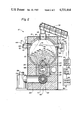
- FIG. 1 is a side elevational view of the particle fuel burning furnace incorporating the improved features of the present invention, with portions broken away to show the inside of the furnace.
- FIG. 2 is an enlarged sectional view of the furnace taken along line 2--2 of FIG. 1.
- FIGS. 1 and 2 of the drawings there is shown a furnace, being indicated generally by the numeral 10, for burning particle fuel 12, for instance, composed of by-products of wood.
- the particle fuel burning furnace 10 incorporates the preferred embodiments of the improved features comprising the present invention and the other invention claimed in the above cross-referenced application.
- the particle fuel burning furnace 10 includes a generally rectangular insulated jacket or housing 14 containing a cylindrical shaped lining 16 formed of refractory material which defines an upper, primary particle fuel retention and combustion chamber 18 and a rectangular shaped lining 20 also formed of refractory material which defines a lower, secondary or afterburning combustion chamber 22.
- Both of the upper and lower combustion chambers 18,22 are generally cylindrical in shape and extend generally parallel to one another. Since the upper chamber 18 also serves as a holding or retention chamber for the solid particle fuel 12, such as sawdust, being burned in the furnace 10, the upper chamber 18 is much larger in diameter than the lower chamber 22, although they both have substantially the same axial length.
- the liner 20 defining the lower chamber 22 has a double wall construction, as seen in FIG. 2, which makes it much thicker than the liner 16 forming the upper chamber 18.
- the cylindrical upper chamber liner 6 is open along its bottom where its laterally spaced edges merge at 24,26 with respective spaced apart upper edges of an outer box-like wall portion 28 of the rectangular liner 20.
- An inner block-like wall portion 30 of the liner 20, which defines the lower chamber 22, nests within the outer wall portion 28 and at its upper surface 32 forms the bottom of the upper chamber 18.
- a series or row of spaced apart, generally vertically-entending passageways 34 which interconnect the bottom of the upper chamber 18 with the top of the lower chamber 22.
- the row of passageways 34 extends in a direction generally parallel to the axial direction of each of the chambers 18,22 while each individual passageway 34 extends in a direction generally perpendicular to the axial direction of the chambers.
- Waste or by-product particle fuel for instance sawdust
- any suitable means such as an auger 36
- the particle fuel falls though the inlet 38 toward the bottom of the upper chamber 18 and forms into a pile 40 which covers the chamber bottom and the passageways 24.
- the pile 40 grows in height within the upper chamber 18 until it reaches a level, as represented by dashed line 42, at which the first improved feature employed by the furnace 10, a particle fuel delivery control device 44, is deactivated to terminate operation of the auger 36.
- the device 44 is again activated, as will be explained hereinafter, to cause operation of the auger 36 for rebuilding the pile 40. Thereafter, periodically, the pile is replenished by delivery of additional particle fuel through the top fuel inlet 38 of the housing 14.
- the furnace 10 is provided with an oil burner 46 mounted to its right wall 48 and in communication with an end of the lower chamber 22.
- the purpose of the oil burner 46 is strictly a backup alternate fuel source and it serves no function or has any effect on the burning operation of the particle fuel 12.
- a particle fuel diversion structure 53 is incorporated into the furnace at the bottom of the upper chamber 18 adjacent to and overlying the passageways 34 leading from the upper chamber to the lower chamber 22.
- the structure 53 creates a pair of slots extending horizontally from the passageways 34 to the upper chamber 18 which relocate the position of the flame at the bottom of the pile 40 and prevent particles of fuel from falling through the passageways 34.
- Suitable heat transfer or recovery means such as coil tubing or a pressure vessel (not shown), is located in either or both of the refractory linings 16,20 for capturing much of the heat produced by burning the particle fuel in the upper chamber 18 and combustible gases in the lower chamber 22.
- most of the fly ash is removed from the remaining products of combustion in the lower chamber 22 by a cyclone ash collector 54 connected in communication with the lower chamber 22 via a branch tunnel 56 (see FIG. 2) connected to the gasification tunnel 51. As the fly ash is collected in the collector 54, the exhaust gases pass to the atmosphere through exhaust conduit 58.
- the furnace 10 as just described is generally identical to the prior art furnace manufactured by Eshland Enterprises, Inc. of Greencastle, Pa. under the trademark "WOOD GUN”.
- the first improved feature incorporated by the particle fuel burning furnace 10 is the particle fuel delivery control device 44 which is operatively arranged in relation to the upper portion of the insulated housing 14 and of the upper chamber 18.
- the device 44 includes a pair of left and right combustion air intake valves 60,62, as viewed in FIG. 2, being mounted through the insulated housing 14 and the cylindrical lining 16 and aligned in a common horizontal plane across the upper half of the upper combustion chamber 18.
- the fan 50 which induces the downward flow of air in the furnace 10 causes inflow of air into the upper chamber 18 through the openings 61,63 of the left and right intake valves 60,62, when they are actuated to their open conditions as seen in solid line form in FIG. 2.
- the valves 60,62 are closed, as seen in the dashed line form, the upper chamber is substantially sealed.
- the valves are thermostatically controlled in a known manner to open when the temperature within the furnace falls below a preset level.
- the air intake valves 60,62 serve a dual function. In addition to providing for infeeding of combustion air when they are open, the valves 60,62 cooperate with the photoelectric cell 66 and a light beam reflector 68.
- the cell 66 is mounted to the right side of the furnace housing 14 by a bracket 70, while the reflector 68 is mounted to the left side of the housing by a bracket 72.
- the cell 66 and reflector 68 are positioned in alignment so as to face one another through the openings 61,63 of the air intake valves 60,62 and across the upper half of the upper chamber 18.
- the cell 66 includes an upper light beam generating element 74 and a lower light receiving element 76.
- the light beam travels along a first path, as represented by broken line 78, through the opening 63 of the right air intake valve 62, across the upper chamber 18, and through the opening 61 of the left air intake valve 60 to where it impinges on the reflector 68.
- the reflector 68 returns the beam along a second path, as represented by broken line 80, through the opening 61 of the left air intake valve 60, back across the upper chamber 18, and through the opening 63 of the right air intake valve 62 to where it impinges on the lower light receiving element 76.
- the photoelectric cell 66 is connected in an electrical circuit, generally designated 82, in series with an auger drive motor 84 and a power source 86, such as an a.c. outlet, for controlling the delivery of particle fuel 12 into the upper chamber 18.
- the circuit 82 is closed and the auger drive motor 84 is turned on so long as the path 78,80 of the light beam across the upper chamber 18 remains uninterrupted. Particle fuel is then delivered by the auger 36 to the upper chamber 18 and the height of the pile 40 therein is increased until the pile interrupts the beam path.
- the valves 60,62 and photoelectric cell 66 and reflector 68 are placed so that the level 42 of the tip of the pile 40 fills and substantially closes the inlet 38 when the side of the pile interrupts the light beam path 78,80. Interruption of the light beam opens the circuit and shuts off the motor 84 which terminates operation of the auger 36 and delivery of fuel.
- a time delay relay 88 is also connected in the circuit 82 in series with the photoelectric cell 66, drive motor 84 and power source 86.
- the relay 88 serves to prevent rapid and repeated starting and stopping of the drive motor 84. Instead, the relay 88 allows the height of the pile 40 to decrease a substantial distance before circuit 82 is again closed by the relay and the drive motor 84 turned back on. It will be readily understood that it takes a much shorter time for the upper chamber 18 to be filled up to the shut off level where the beam is interrupted than for the height of the pile 40 to decrease a corresponding distance due to burning of the fuel. Thus, for particle fuel material, such as sawdust, a time delay setting of 3-5 minutes would be normal.
- the particle fuel diversion structure 53 extends the useful life of the refractory materials in which the passageways 34 are formed and alleviates the filling of the lower chamber 22 with particles of fuel.
- the diversion structure 53 includes an elongated fuel diverter block 90 having a solid construction and a generally triangular cross-sectional shape and at least a pair of spacer blocks 92 located below either end of the diverter block 90 for elevating it above the the upper surface 32 of the inner wall portion 30 of the liner 20 which has the lower chamber 22 and passageways 34 formed therein.
- the triangular configuration of the diverter block 90 provides a pair of surfaces 94,96 which slope downwardly and oppositely outwardly away from an upper central edge 95 of the block 90 displaced above the row of passageways 34 and thereby direct the flow of particles of fuel 12 away from the passageways 34 so as to prevent small particles from falling through the passageways or from being drawn into the lower chamber 22 by a downdraft.
- the triangular configuration of the diverter block 90 and the elevation of the diverter block 90 by the spacer blocks 92 above the liner 20 provides a bottom surface 98 on the block 90 which is spaced above the upper surface 32 of the liner 20 so as to create a pair of slots 100,102 which extend from each opposite lower lateral edge 104,106 of the diverter block 90 to the passageways 34.
- the slots 100,102 become the location of the flame burning the particle fuel in the upper chamber 18 rather than the passageways 34 which was the case in absence of the diverter block 90.
- flame erosion takes place on the lateral edges 104,106 of the diverter block 90 rather than in the passageways 34.
- the service life of the refractory material comprising the lower chamber 22 is greatly extended, while a relatively inexpensive diverter block can now be replaced very easily on a periodic basis.
Abstract
Description
Claims (6)
Priority Applications (3)
| Application Number | Priority Date | Filing Date | Title |
|---|---|---|---|
| US06/632,998 US4531464A (en) | 1984-07-20 | 1984-07-20 | Particle fuel diversion structure |
| CA000465163A CA1228508A (en) | 1984-07-20 | 1984-10-11 | Particle fuel diversion structure |
| EP85108851A EP0168808A3 (en) | 1984-07-20 | 1985-07-15 | Particle fuel diversion apparatus |
Applications Claiming Priority (1)
| Application Number | Priority Date | Filing Date | Title |
|---|---|---|---|
| US06/632,998 US4531464A (en) | 1984-07-20 | 1984-07-20 | Particle fuel diversion structure |
Publications (1)
| Publication Number | Publication Date |
|---|---|
| US4531464A true US4531464A (en) | 1985-07-30 |
Family
ID=24537860
Family Applications (1)
| Application Number | Title | Priority Date | Filing Date |
|---|---|---|---|
| US06/632,998 Expired - Fee Related US4531464A (en) | 1984-07-20 | 1984-07-20 | Particle fuel diversion structure |
Country Status (3)
| Country | Link |
|---|---|
| US (1) | US4531464A (en) |
| EP (1) | EP0168808A3 (en) |
| CA (1) | CA1228508A (en) |
Cited By (18)
| Publication number | Priority date | Publication date | Assignee | Title |
|---|---|---|---|---|
| EP0214010A1 (en) * | 1985-08-09 | 1987-03-11 | CHAUBOIS TECHNOLOGIE Inc. | Burner with a gasifying stage for a heating device, and heating device comprising such a burner |
| EP0240445A1 (en) * | 1986-04-02 | 1987-10-07 | De Dietrich Thermique | Sectional-type cast iron boiler for solid fuels comprising a fireproof afterburning channel |
| FR2596851A1 (en) * | 1986-04-02 | 1987-10-09 | Dietrich & Cie De | Solid fuel boiler of the type having inverted combustion and a refractory post-combustion channel |
| FR2597958A1 (en) * | 1986-04-25 | 1987-10-30 | Chaubois Technologie Inc | GAS BURNER FOR HEATING APPARATUS AND HEATING APPARATUS COMPRISING SUCH A BURNER |
| EP0246147A1 (en) * | 1986-05-15 | 1987-11-19 | Claude Fontaine | Incinerator for urban waste |
| US4850289A (en) * | 1986-12-11 | 1989-07-25 | Harris Beausoleil | Incinerator |
| US5289787A (en) * | 1992-12-09 | 1994-03-01 | Eshleman Roger D | Multiple unit material processing apparatus |
| WO1994014006A1 (en) * | 1992-12-09 | 1994-06-23 | Eshleman Roger D | Casing and heater configuration |
| US5323716A (en) * | 1993-09-17 | 1994-06-28 | Eshleman Roger D | Heater and tunnel arrangement in a material processing apparatus |
| US5338918A (en) * | 1992-12-09 | 1994-08-16 | Eshleman Roger D | Heat generator assembly in a material processing apparatus |
| US5353719A (en) * | 1992-12-09 | 1994-10-11 | Eshleman Roger D | Apparatus and method for controlled processing of materials |
| US5361709A (en) * | 1993-09-17 | 1994-11-08 | Eshleman Roger D | Material transport pusher mechanism in a material processing apparatus |
| US5417170A (en) * | 1993-09-17 | 1995-05-23 | Eshleman; Roger D. | Sloped-bottom pyrolysis chamber and solid residue collection system in a material processing apparatus |
| US5428205A (en) * | 1993-09-17 | 1995-06-27 | Eshleman; Roger D. | Casing and heater configuration in a material processing apparatus |
| EP1085259A1 (en) * | 1999-09-15 | 2001-03-21 | LIGNOTECH Entwicklung von Biomassefeuerungsanlagen GmbH | Device for burning biogenous fuels |
| US20090183693A1 (en) * | 2008-01-02 | 2009-07-23 | Furman Dale C | High efficiency wood or biomass boiler |
| ITUB20160989A1 (en) * | 2016-02-23 | 2017-08-23 | Stefano Salvatico | COMBUSTION SYSTEM |
| EP3715714A1 (en) * | 2019-03-25 | 2020-09-30 | Schmid AG - Energy Solutions | Method for controlling the fuel level of a biomass boiler |
Families Citing this family (1)
| Publication number | Priority date | Publication date | Assignee | Title |
|---|---|---|---|---|
| SE8804032D0 (en) * | 1988-11-08 | 1988-11-08 | APPLICATION FOR COMBUSTION OF THE FIXED BRAZENAL BENEFITS |
Citations (5)
| Publication number | Priority date | Publication date | Assignee | Title |
|---|---|---|---|---|
| US2069584A (en) * | 1932-01-29 | 1937-02-02 | Lorton Pierre | Furnace for the incineration of household refuse |
| US3861332A (en) * | 1972-08-10 | 1975-01-21 | Ebara Infilco | Incinerator for unsegregated refuse |
| US4048927A (en) * | 1974-09-14 | 1977-09-20 | Kernforschungsanlage Julich Gesellschaft Mit Beschrankter Haftung | Plant for burning waste |
| US4274341A (en) * | 1978-12-07 | 1981-06-23 | Ozaltay Huseyin C | Coal gasifying burner with rotating grill |
| US4452611A (en) * | 1982-05-24 | 1984-06-05 | Richey Clarence B | Downdraft channel biomass gasifier |
Family Cites Families (6)
| Publication number | Priority date | Publication date | Assignee | Title |
|---|---|---|---|---|
| FR895629A (en) * | 1941-04-29 | 1945-01-30 | Boiler | |
| FR1200301A (en) * | 1958-03-28 | 1959-12-21 | Solid fuel fireplace | |
| DE1141767B (en) * | 1958-12-22 | 1962-12-27 | Kaiser Thier stem Wilhelm (OFr ) | Space heater for waste fuel. |
| US4194487A (en) * | 1976-08-02 | 1980-03-25 | Cadwallader John Y | Downdraft woodburning stove |
| DE2735139C2 (en) * | 1977-08-04 | 1982-05-06 | Kernforschungsanlage Jülich GmbH, 5170 Jülich | Incinerator for waste |
| US4380228A (en) * | 1981-04-21 | 1983-04-19 | Crowley Leslie B | Sustained ignition secondary combustion unit |
-
1984
- 1984-07-20 US US06/632,998 patent/US4531464A/en not_active Expired - Fee Related
- 1984-10-11 CA CA000465163A patent/CA1228508A/en not_active Expired
-
1985
- 1985-07-15 EP EP85108851A patent/EP0168808A3/en not_active Withdrawn
Patent Citations (5)
| Publication number | Priority date | Publication date | Assignee | Title |
|---|---|---|---|---|
| US2069584A (en) * | 1932-01-29 | 1937-02-02 | Lorton Pierre | Furnace for the incineration of household refuse |
| US3861332A (en) * | 1972-08-10 | 1975-01-21 | Ebara Infilco | Incinerator for unsegregated refuse |
| US4048927A (en) * | 1974-09-14 | 1977-09-20 | Kernforschungsanlage Julich Gesellschaft Mit Beschrankter Haftung | Plant for burning waste |
| US4274341A (en) * | 1978-12-07 | 1981-06-23 | Ozaltay Huseyin C | Coal gasifying burner with rotating grill |
| US4452611A (en) * | 1982-05-24 | 1984-06-05 | Richey Clarence B | Downdraft channel biomass gasifier |
Cited By (24)
| Publication number | Priority date | Publication date | Assignee | Title |
|---|---|---|---|---|
| EP0214010A1 (en) * | 1985-08-09 | 1987-03-11 | CHAUBOIS TECHNOLOGIE Inc. | Burner with a gasifying stage for a heating device, and heating device comprising such a burner |
| EP0240445A1 (en) * | 1986-04-02 | 1987-10-07 | De Dietrich Thermique | Sectional-type cast iron boiler for solid fuels comprising a fireproof afterburning channel |
| FR2596851A1 (en) * | 1986-04-02 | 1987-10-09 | Dietrich & Cie De | Solid fuel boiler of the type having inverted combustion and a refractory post-combustion channel |
| FR2597958A1 (en) * | 1986-04-25 | 1987-10-30 | Chaubois Technologie Inc | GAS BURNER FOR HEATING APPARATUS AND HEATING APPARATUS COMPRISING SUCH A BURNER |
| EP0246147A1 (en) * | 1986-05-15 | 1987-11-19 | Claude Fontaine | Incinerator for urban waste |
| FR2598783A1 (en) * | 1986-05-15 | 1987-11-20 | Claude Fontaine | INCINERATOR OF URBAN WASTE. |
| US4785744A (en) * | 1986-05-15 | 1988-11-22 | Claude Fontaine | Incinerator of urban wastes |
| US4850289A (en) * | 1986-12-11 | 1989-07-25 | Harris Beausoleil | Incinerator |
| US5353719A (en) * | 1992-12-09 | 1994-10-11 | Eshleman Roger D | Apparatus and method for controlled processing of materials |
| US5501159A (en) * | 1992-12-09 | 1996-03-26 | Bio-Oxidation, Inc. | Method of controlling hydrocarbon release rate by maintaining target oxygen concentration in discharge gases |
| WO1994014006A1 (en) * | 1992-12-09 | 1994-06-23 | Eshleman Roger D | Casing and heater configuration |
| US5338918A (en) * | 1992-12-09 | 1994-08-16 | Eshleman Roger D | Heat generator assembly in a material processing apparatus |
| US5289787A (en) * | 1992-12-09 | 1994-03-01 | Eshleman Roger D | Multiple unit material processing apparatus |
| US5420394A (en) * | 1992-12-09 | 1995-05-30 | Eshleman; Roger D. | Casing and heater configuration in a material processing apparatus |
| WO1995008079A1 (en) * | 1993-09-17 | 1995-03-23 | Eshleman Roger D | Material transport pusher mechanism |
| US5417170A (en) * | 1993-09-17 | 1995-05-23 | Eshleman; Roger D. | Sloped-bottom pyrolysis chamber and solid residue collection system in a material processing apparatus |
| US5361709A (en) * | 1993-09-17 | 1994-11-08 | Eshleman Roger D | Material transport pusher mechanism in a material processing apparatus |
| US5428205A (en) * | 1993-09-17 | 1995-06-27 | Eshleman; Roger D. | Casing and heater configuration in a material processing apparatus |
| US5323716A (en) * | 1993-09-17 | 1994-06-28 | Eshleman Roger D | Heater and tunnel arrangement in a material processing apparatus |
| EP1085259A1 (en) * | 1999-09-15 | 2001-03-21 | LIGNOTECH Entwicklung von Biomassefeuerungsanlagen GmbH | Device for burning biogenous fuels |
| US20090183693A1 (en) * | 2008-01-02 | 2009-07-23 | Furman Dale C | High efficiency wood or biomass boiler |
| US8640655B2 (en) | 2008-01-02 | 2014-02-04 | Dale C. Furman | High efficiency wood or biomass boiler |
| ITUB20160989A1 (en) * | 2016-02-23 | 2017-08-23 | Stefano Salvatico | COMBUSTION SYSTEM |
| EP3715714A1 (en) * | 2019-03-25 | 2020-09-30 | Schmid AG - Energy Solutions | Method for controlling the fuel level of a biomass boiler |
Also Published As
| Publication number | Publication date |
|---|---|
| EP0168808A3 (en) | 1986-12-17 |
| CA1228508A (en) | 1987-10-27 |
| EP0168808A2 (en) | 1986-01-22 |
Similar Documents
| Publication | Publication Date | Title |
|---|---|---|
| US4531464A (en) | Particle fuel diversion structure | |
| US4513671A (en) | Particle fuel delivery control device | |
| US4598649A (en) | Particle fuel diversion structure with dome-shaped cavity | |
| US4385567A (en) | Solid fuel conversion system | |
| WO1984002385A1 (en) | A solid fuel stoker | |
| PT85500A (en) | UNDERSTANDING TANK FOR BURNING SOLID COMBUSTIVE | |
| CA1198630A (en) | Burner for combusting granular fuel | |
| CN211999600U (en) | Biomass particle pyrolysis semi-gasification stove | |
| CN206803124U (en) | A kind of gasification combustion system | |
| CN215062014U (en) | Sliding deslagging biomass combustion furnace | |
| CN2347056Y (en) | Mechanical fire grate coal-burning gasified burner | |
| CN106524132A (en) | Solid fuel burning stove | |
| CN111457362A (en) | Horizontal shaking type bubbling fluidized bed combustion device | |
| CN114636148A (en) | Biomass fuel and coal are burner in coordination | |
| SU767456A1 (en) | Apparatus for burning industrial wastes | |
| CN111394138A (en) | Biomass particle pyrolysis semi-gasification stove | |
| EP0200730A1 (en) | Boiler with a shaking grate | |
| CN2125771U (en) | Prefix furnace for cane chaft-coal powder mixed combustion boiler | |
| JPS6044710A (en) | Hot blast generating furnace | |
| Lunny | GRATE FIRING OF PEAT FUELS | |
| GB190917375A (en) | Improvements in Boiler Furnaces. | |
| JPS6120765B2 (en) | ||
| Hofft | Design of Furnaces and Fuel Feeders for Burning Refuse | |
| CN105698188A (en) | Garbage incinerator | |
| UA16209A1 (en) | Combustor |
Legal Events
| Date | Code | Title | Description |
|---|---|---|---|
| AS | Assignment |
Owner name: ESHLAND ENTERPRISES, INC. 120 EAST GRANT STREET GR Free format text: ASSIGNMENT OF ASSIGNORS INTEREST.;ASSIGNOR:ESHLEMAN, ROGER D.;REEL/FRAME:004290/0613 Effective date: 19840709 Owner name: ESHLAND ENTERPRISES, INC., A CORP OF PA,PENNSYLVAN Free format text: ASSIGNMENT OF ASSIGNORS INTEREST;ASSIGNOR:ESHLEMAN, ROGER D.;REEL/FRAME:004290/0613 Effective date: 19840709 |
|
| FPAY | Fee payment |
Year of fee payment: 4 |
|
| FPAY | Fee payment |
Year of fee payment: 8 |
|
| REMI | Maintenance fee reminder mailed | ||
| LAPS | Lapse for failure to pay maintenance fees | ||
| FP | Lapsed due to failure to pay maintenance fee |
Effective date: 19970730 |
|
| AS | Assignment |
Owner name: BIO-OXIDATION INC., PENNSYLVANIA Free format text: MERGER;ASSIGNOR:ESHLAND ENTERPRISES, INC.;REEL/FRAME:008933/0355 Effective date: 19940228 |
|
| AS | Assignment |
Owner name: BIO-OXIDATION SERVICES INC., MARYLAND Free format text: CHANGE OF NAME;ASSIGNOR:BIO-OXIDATION INC., SOMETIMES TRADING AS "BIO-OXIDATION";REEL/FRAME:009922/0499 Effective date: 19980306 |
|
| STCH | Information on status: patent discontinuation |
Free format text: PATENT EXPIRED DUE TO NONPAYMENT OF MAINTENANCE FEES UNDER 37 CFR 1.362 |