US45307A - Improvement in magazine fire-arms - Google Patents
Improvement in magazine fire-arms Download PDFInfo
- Publication number
- US45307A US45307A US45307DA US45307A US 45307 A US45307 A US 45307A US 45307D A US45307D A US 45307DA US 45307 A US45307 A US 45307A
- Authority
- US
- United States
- Prior art keywords
- magazine
- spring
- follower
- barrel
- contractor
- Prior art date
- Legal status (The legal status is an assumption and is not a legal conclusion. Google has not performed a legal analysis and makes no representation as to the accuracy of the status listed.)
- Expired - Lifetime
Links
- 238000004140 cleaning Methods 0.000 description 1
- 230000008602 contraction Effects 0.000 description 1
- 238000010304 firing Methods 0.000 description 1
- 239000002184 metal Substances 0.000 description 1
- MFOUDYKPLGXPGO-UHFFFAOYSA-N propachlor Chemical compound ClCC(=O)N(C(C)C)C1=CC=CC=C1 MFOUDYKPLGXPGO-UHFFFAOYSA-N 0.000 description 1
Images

Classifications
-
- F—MECHANICAL ENGINEERING; LIGHTING; HEATING; WEAPONS; BLASTING
- F41—WEAPONS
- F41A—FUNCTIONAL FEATURES OR DETAILS COMMON TO BOTH SMALLARMS AND ORDNANCE, e.g. CANNONS; MOUNTINGS FOR SMALLARMS OR ORDNANCE
- F41A9/00—Feeding or loading of ammunition; Magazines; Guiding means for the extracting of cartridges
- F41A9/61—Magazines
- F41A9/64—Magazines for unbelted ammunition
- F41A9/72—Tubular magazines, i.e. magazines containing the ammunition in lengthwise tandem sequence
Definitions
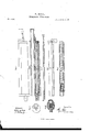
- FIG. 1 is a side view of the barrel of a repeating tire-arm with my invention applied to it, while Fig. 2 is a longitudinal section; Fig. 3, a front-end view 5 Fig. 4, a transverse section thereof.
- Fig. 5 is a longitudinal section of the spring-contractor, to be hereinafter dcscribed.
- Fig. 6 is a side view of themagazine with its spring-contractor trough and tipband.
- Fig. 7 is a longitudinal section of the magazine, the spring and follower thereof, and also the stop-pawl and the series of holes by which the follower is prevented from being forced back against the spring by the cartridge or cartridges.
- A denotes the barrel of a repeating fire-arm, there being arranged underneath the barrel a tube or magazine, B, for holding a series of cartridges.
- a tube or magazine for holding a series of cartridges.
- a thimble-shaped follower or slider U
- a helical spring D
- a spring-contractor,77 E For drawing the follower forward within the magazine in order to contract the spring D, what may be termed a spring-contractor,77 E, is employed, it being somewhat like a ramrod, and made in two parts or lengths, a b, the longer of which, b, is provided at its rearend with a male screw, to screw into the front end of the shorter part a, such shorter part a being furnished with a hook or projection, c, eX- tending laterally from it at its rear end'.
- the spring contractor so made is placed alongside of the magazine, and in a trough or tube, d, which is fastened to the magazine, and opens into it by a slit, c, extending nearly l if not entirely throughout the length of the magazine.
- This slit is for the reception of the shorter arm of a lever-catch or stop-catch, j', which is formed and arranged within the follower 0 in manner as shown in Fig. 7.
- spring, g operates to force the hook h of the catch f through an opening in the side of the follower.
- a series of holes, c' i Ii, is made through the side of the magazine, and at distances apart from one another equal to the lengths of the cartridges to be used in the magazine.
- the hook 71 Whenever the follower is at rest in the magazine, the hook 71, will be in some one of the holes, and will prevent the cartridge or collection of' cartridges from being moved so as to force the follower against the spring D in such manner as to contract it or produce longitudinal retraction of it.
- the object of the stop-catch f and the holes fi i z' t' is to prevent longitudinal vibrations of the cartridge or cartridges in the magazine.
- a spring lever-latch, F supported by the metallic tip-band G and arranged and formed as shown in Fig. 2, will catch the follower at 7the extreme position of its retraction, and
- a spring, l, affixed to the latch in advance of its fulcrum, serves to throw the latch into engagement with the follower at the proper time.
- the tip-.band Gr is screwed to the front end of the magazine tube and goes around the barrel, and not only forms a head to the magazine, but constitutes a support for the latch F.
- the purpose of the latch F is to hold the magazine or follower sprin gD contracted while the magazine may be in the act ofbein g charged with cartridges, for the purpose of constructing the spring-contractor in ⁇ the manner as explained is to allow of its longer part b being separated from the shorter part a and withdrawn from the trough d, in order that such part b may be employed either as a rammer to expel a cartridge from the barrel or for any othernseful purpose, it being also especially advantageous for effecting the cleaning of the inside of the barrel, in which case it is to be supposed to be screwed to a wiper to be run into the barrel.
- the contractor E is arranged alongside of the magazine and the lever-latch F, instead of being passed underneath the barrel. This enables the said latch to be disposed directly underneath the barrel.
- the magazine slides endwise into a wooden cover or stock, I, which ts to it and the bar- ⁇ rel, and is held in place by the tip-band and by a back band, K, the tip-band being held to the barrel by means ot' a screw, n.
- the barrel by being separate from the magazine, not only can expand lengthwise when heated without producing a corresponding expansion of the magazine, but it becomes so insulated from the magazine as not to heat it and the cartridges so as to iniiame the percussion-priming of any one of the latter.
- the wooden cover I prevents dirt or foreign matters from getting into the contractor-case and the magazine and impeding the action of the parts therein.
- I claim- 1 The arrangement and combination of the spring-contractor E with the barrel and the magazine, provided with a spring and follower, as specified.
Landscapes
- Engineering & Computer Science (AREA)
- General Engineering & Computer Science (AREA)
- Portable Nailing Machines And Staplers (AREA)
Description
A B A LL.
- Magazine Fire-arm.
' Patented Dec. 6, 1864.
VN.PF.'\ERS. PHOTO-LITHOGRAPHER, wAsHlNGTON. D C
UNITED STATES PATENT ALBERT BALL, OF WORCESTER, MASSACHUSETTS.
IMDR'OVEMENT IN MAGAZINE FIRE-ARMS.
Specification forming part of Letters Patent No. 45,307, dated December 6, 1864.
To all whom t may concern:
Beit known that I, ALBERT BALL, of the city and county of Worcester, and State of Massachusetts, have made a new and useful invention having reference to Repeating Fire- Arms; and do hereby declare the same to be fully described in the following specification and represented in the accompanying drawings, of' which- Figure 1 is a side view of the barrel of a repeating tire-arm with my invention applied to it, while Fig. 2 is a longitudinal section; Fig. 3, a front-end view 5 Fig. 4, a transverse section thereof. Fig. 5 is a longitudinal section of the spring-contractor, to be hereinafter dcscribed. Fig. 6 is a side view of themagazine with its spring-contractor trough and tipband. Fig. 7 is a longitudinal section of the magazine, the spring and follower thereof, and also the stop-pawl and the series of holes by which the follower is prevented from being forced back against the spring by the cartridge or cartridges.
In these drawings, A denotes the barrel of a repeating lire-arm, there being arranged underneath the barrel a tube or magazine, B, for holding a series of cartridges. Within this tube or magazine there is a thimble-shaped follower or slider, U, and a helical spring, D, the latter being for moving the follower rearward, in order to propel the several cartridges along toward the breech end of' the barrel, as circumstances may require.
For drawing the follower forward within the magazine in order to contract the spring D, what may be termed a spring-contractor,77 E, is employed, it being somewhat like a ramrod, and made in two parts or lengths, a b, the longer of which, b, is provided at its rearend with a male screw, to screw into the front end of the shorter part a, such shorter part a being furnished with a hook or projection, c, eX- tending laterally from it at its rear end'.
The spring contractor so made is placed alongside of the magazine, and in a trough or tube, d, which is fastened to the magazine, and opens into it by a slit, c, extending nearly l if not entirely throughout the length of the magazine. This slit is for the reception of the shorter arm of a lever-catch or stop-catch, j', which is formed and arranged within the follower 0 in manner as shown in Fig. 7. A
spring, g, operates to force the hook h of the catch f through an opening in the side of the follower.
A series of holes, c' i Ii, is made through the side of the magazine, and at distances apart from one another equal to the lengths of the cartridges to be used in the magazine. Whenever the follower is at rest in the magazine, the hook 71, will be in some one of the holes, and will prevent the cartridge or collection of' cartridges from being moved so as to force the follower against the spring D in such manner as to contract it or produce longitudinal retraction of it. The object of the stop-catch f and the holes fi i z' t' is to prevent longitudinal vibrations of the cartridge or cartridges in the magazine.
By pulling forward the contractor E the follower Inay be drawn into the magazine, so as to contract the spring thereof. In this operation the hook of the contractor will so act against the stop-catch f as to cause its hook h to move back entirely within the follower, in order to enable the latter to be moved along into and within the magazine. Furthermore, besides such action, the hook of the contractor will retain such a hold on the lever stop-catch as to effect the retraction of the follower during the forward movement of' the retractor.
A spring lever-latch, F, supported by the metallic tip-band G and arranged and formed as shown in Fig. 2, will catch the follower at 7the extreme position of its retraction, and
hold it there until such latch may be relieved from the follower, which may be accomplished by pressing the shorter arm lc of the latch toward the barrel. A spring, l, affixed to the latch in advance of its fulcrum, serves to throw the latch into engagement with the follower at the proper time.
The tip-.band Gr is screwed to the front end of the magazine tube and goes around the barrel, and not only forms a head to the magazine, but constitutes a support for the latch F.
The purpose of the latch F is to hold the magazine or follower sprin gD contracted while the magazine may be in the act ofbein g charged with cartridges, for the purpose of constructing the spring-contractor in` the manner as explained is to allow of its longer part b being separated from the shorter part a and withdrawn from the trough d, in order that such part b may be employed either as a rammer to expel a cartridge from the barrel or for any othernseful purpose, it being also especially advantageous for effecting the cleaning of the inside of the barrel, in which case it is to be supposed to be screwed to a wiper to be run into the barrel. The contractor E is arranged alongside of the magazine and the lever-latch F, instead of being passed underneath the barrel. This enables the said latch to be disposed directly underneath the barrel.
The magazine slides endwise into a wooden cover or stock, I, which ts to it and the bar-` rel, and is held in place by the tip-band and by a back band, K, the tip-band being held to the barrel by means ot' a screw, n.
The barrel, by being separate from the magazine, not only can expand lengthwise when heated without producing a corresponding expansion of the magazine, but it becomes so insulated from the magazine as not to heat it and the cartridges so as to iniiame the percussion-priming of any one of the latter.
The uniform expansion or contraction of the barrel, (when heated,) gained by having the magazine and barrel separate from one another, as specified, insures greater accuracy of firing; for when both are in one piece of metal, or so combined that the expansion of one cannot take place equally With that of the other, the barrel is likely to become heated irregularly, or fastest where it may be the thinnest, and so as to crook or bend more or less, and thereby injuriously affect the proper direction of a ball while being discharged from it. The wooden cover I prevents dirt or foreign matters from getting into the contractor-case and the magazine and impeding the action of the parts therein.
I claim- 1. The arrangement and combination of the spring-contractor E with the barrel and the magazine, provided with a spring and follower, as specified.
2. I also claim the spring-contractor, made substantially as described.
3. I also claim the combination of the leverlatch F, or its mechanical equivalent, with the magazine, the spring and follower thereof, and the spring-contractor.
4. I also claim the combination and arrangementot1 the tip-band Gr with the barrel, the magazine, the lever-latch, and the spring-contractor, substantially as setfort-h.
ALBERT BALL.
Witnesses E. E. LAMsEN, CARLOS OOOLIDGE.
Publications (1)
| Publication Number | Publication Date |
|---|---|
| US45307A true US45307A (en) | 1864-12-06 |
Family
ID=2114868
Family Applications (1)
| Application Number | Title | Priority Date | Filing Date |
|---|---|---|---|
| US45307D Expired - Lifetime US45307A (en) | Improvement in magazine fire-arms |
Country Status (1)
| Country | Link |
|---|---|
| US (1) | US45307A (en) |
-
0
- US US45307D patent/US45307A/en not_active Expired - Lifetime
Similar Documents
| Publication | Publication Date | Title |
|---|---|---|
| US45307A (en) | Improvement in magazine fire-arms | |
| US658010A (en) | Magazine-pistol. | |
| US987350A (en) | Firearm. | |
| US125829A (en) | Improvement ih breech-loading fire-arms | |
| US44784A (en) | Improvement in combined gun and pistol bayonet | |
| US51837A (en) | Improvement in revolving fire-arms | |
| US124056A (en) | Improvement in breech-loading fire-arms | |
| US1041109A (en) | Magazine-gun. | |
| US97821A (en) | Fire-arms | |
| US43827A (en) | Improvement in self-feeding breech-loading fire-arm | |
| US54934A (en) | Improvement in breech-loading fire-arms | |
| US39246A (en) | Improvement in breech-loading fire-arms | |
| US57808A (en) | Improvement in magazine fire-arms | |
| US50854A (en) | Improvement in cartridge-retractors for breech-loading fire-arms | |
| US20776A (en) | Improvement in breech-loading fire-arms | |
| US45466A (en) | John f | |
| US1094729A (en) | Firearm. | |
| US44995A (en) | Improvement in breech-loading fire-arms | |
| US910236A (en) | Magazine-firearm. | |
| US42685A (en) | Improvement in breech-loading fire-arms | |
| US180216A (en) | Improvement in breech-loading fire-arms | |
| US45262A (en) | Improvement in breech-loadsng fire-arms | |
| US13474A (en) | Improvement in breech-loading magazine fire-arms | |
| US142396A (en) | Improvement in breech-loading fire-arms | |
| US42227A (en) | Improvement in breech-loading fire-arms |