US4528015A - Glass forming blank and plunger cooling - Google Patents
Glass forming blank and plunger cooling Download PDFInfo
- Publication number
- US4528015A US4528015A US06/472,297 US47229783A US4528015A US 4528015 A US4528015 A US 4528015A US 47229783 A US47229783 A US 47229783A US 4528015 A US4528015 A US 4528015A
- Authority
- US
- United States
- Prior art keywords
- manifold
- cooling air
- pressure regulator
- cooling
- pilot
- Prior art date
- Legal status (The legal status is an assumption and is not a legal conclusion. Google has not performed a legal analysis and makes no representation as to the accuracy of the status listed.)
- Expired - Lifetime
Links
- 238000001816 cooling Methods 0.000 title claims abstract description 36
- 238000007496 glass forming Methods 0.000 title description 2
- 230000007246 mechanism Effects 0.000 claims abstract description 23
- 230000001105 regulatory effect Effects 0.000 claims description 9
- 230000001276 controlling effect Effects 0.000 claims description 3
- 239000012809 cooling fluid Substances 0.000 claims 1
- 230000008859 change Effects 0.000 description 4
- 239000012530 fluid Substances 0.000 description 4
- 230000004075 alteration Effects 0.000 description 1
- 238000010586 diagram Methods 0.000 description 1
- 239000011521 glass Substances 0.000 description 1
- 230000004048 modification Effects 0.000 description 1
- 238000012986 modification Methods 0.000 description 1
- 230000009467 reduction Effects 0.000 description 1
- 230000000007 visual effect Effects 0.000 description 1
Images

Classifications
-
- C—CHEMISTRY; METALLURGY
- C03—GLASS; MINERAL OR SLAG WOOL
- C03B—MANUFACTURE, SHAPING, OR SUPPLEMENTARY PROCESSES
- C03B9/00—Blowing glass; Production of hollow glass articles
- C03B9/30—Details of blowing glass; Use of materials for the moulds
- C03B9/38—Means for cooling, heating, or insulating glass-blowing machines or for cooling the glass moulded by the machine
- C03B9/3816—Means for general supply, distribution or control of the medium to the mould, e.g. sensors, circuits, distribution networks
-
- Y—GENERAL TAGGING OF NEW TECHNOLOGICAL DEVELOPMENTS; GENERAL TAGGING OF CROSS-SECTIONAL TECHNOLOGIES SPANNING OVER SEVERAL SECTIONS OF THE IPC; TECHNICAL SUBJECTS COVERED BY FORMER USPC CROSS-REFERENCE ART COLLECTIONS [XRACs] AND DIGESTS
- Y10—TECHNICAL SUBJECTS COVERED BY FORMER USPC
- Y10T—TECHNICAL SUBJECTS COVERED BY FORMER US CLASSIFICATION
- Y10T137/00—Fluid handling
- Y10T137/8593—Systems
- Y10T137/877—With flow control means for branched passages
- Y10T137/87788—With valve or movable deflector at junction
- Y10T137/8782—Rotary valve or deflector
-
- Y—GENERAL TAGGING OF NEW TECHNOLOGICAL DEVELOPMENTS; GENERAL TAGGING OF CROSS-SECTIONAL TECHNOLOGIES SPANNING OVER SEVERAL SECTIONS OF THE IPC; TECHNICAL SUBJECTS COVERED BY FORMER USPC CROSS-REFERENCE ART COLLECTIONS [XRACs] AND DIGESTS
- Y10—TECHNICAL SUBJECTS COVERED BY FORMER USPC
- Y10T—TECHNICAL SUBJECTS COVERED BY FORMER US CLASSIFICATION
- Y10T137/00—Fluid handling
- Y10T137/8593—Systems
- Y10T137/877—With flow control means for branched passages
- Y10T137/87877—Single inlet with multiple distinctly valved outlets
-
- Y—GENERAL TAGGING OF NEW TECHNOLOGICAL DEVELOPMENTS; GENERAL TAGGING OF CROSS-SECTIONAL TECHNOLOGIES SPANNING OVER SEVERAL SECTIONS OF THE IPC; TECHNICAL SUBJECTS COVERED BY FORMER USPC CROSS-REFERENCE ART COLLECTIONS [XRACs] AND DIGESTS
- Y10—TECHNICAL SUBJECTS COVERED BY FORMER USPC
- Y10T—TECHNICAL SUBJECTS COVERED BY FORMER US CLASSIFICATION
- Y10T137/00—Fluid handling
- Y10T137/8593—Systems
- Y10T137/877—With flow control means for branched passages
- Y10T137/87909—Containing rotary valve
Definitions
- This invention relates generally to improved blank and plunger cooling. More particularly, this invention relates to improved blank and plunger cooling for use in conjunction with a glass forming machine of the press and blow type which is a single table, continuous rotary machine having a plurality of individual forming units mounted for rotation about the axis of the machine.
- a glass forming machine of the press and blow type which is a single table, continuous rotary machine having a plurality of individual forming units mounted for rotation about the axis of the machine.
- This type of machine is shown in U.S. Pat. No. 1,979,211 which issued on Oct. 30, 1934 to G. E. Rowe. Machines of this type are commonly used in the glass industry today and are known as the "Emhart H-28 Machine.”
- the type of machine shown in the No. 1,978,201 U.S. patent is a single gob machine. That is, at each forming unit, only one piece of ware is produced during a single cycle of each forming unit.
- Each forming unit on the machine shown in the 4,339,264 patent has inner nd outer plungers and inner and outer blank mold side walls and inner and outer blank mold bottom walls all which must be cooled by a fluid such as air.
- the inlet cooling conduits to each of these mechanisms to be cooled were provided with an adjustment valve which was required to be adjusted to change the amount of cooling each mechanism would receive.
- 72 valves are required to be adjusted for proper operation of the machine. The requirement of having to adjust 72 valves was a relatively inefficient way of controlling the amount of cooling to the plungers and blank molds and resulted in a reduction of the performance of the machine.
- a more specific object of the present invention is a provision on a more efficient manner of regulating the cooling for the plungers and blank molds of machine having a plurality of individual sections.
- a control air system for use with a glassware making machine having a plurality of individual units each having a plurality of different mechanisms to be cooled and each individual unit having the same mechanism as the others.
- a manifold is associated with each mechanism and each manifold has an inlet line connecting it to a source of cooling air.
- a pilot operated pressure regulator is in each inlet line.
- Means are provided for connecting each manifold with its associated mechanism in all the forming units.
- Means are also associated with each of said pressure regulator to individually control the flow of pilot air to each pressure regulator.
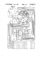
- FIG. 1 is a schematic flow diagram of the piping for the plunger and blow mold cooling.
- FIG. 2 is a schematic representation of the upper portion of a continuous rotary motion machine showing the various manifolds used in connection with the cooling of the plunger and blank molds.
- FIG. 1 a single table, continuous rotary motion machine of the type shown in U.S. Pat. No. 4,339,264 is indicated schematically by the reference numeral 2.
- the machine like the one in the 4,339,264 patent has twelve individual forming units or sections 4 each capable of forming two articles of glassware during one cycle which are attached to a rotating turrent ring 6 at the various location 8.
- the sections 4 are shown schematically at the bottom of FIG. 1.
- High pressure air is fed to a rotating fluid distributor 10 on the top of the machine by a stationery air inlet pipe 12.
- a shut-off valve 14 is provided in the air inlet.
- Six lines 16 extend from the fluid distributor 10 to a different one of six pilot operated pressure regulators 18.
- the outlet of each regulator 18 is connected to a different one of six circular manifolds 20, which are mounted one on top of the other on suitable brackets 22 at the top of the machine, by a line 24.
- Each manifold is connected by suitable lines, 26 to each forming unit to provide cooling air for its designated mechanism.
- suitable lines, 26 to each forming unit to provide cooling air for its designated mechanism.
- Each manifold provides for the cooling of a different mechanism.
- the upper manifold may provide cooling air for cooling the inner plunger.
- the next manifold may provide cooling air for cooling the outer plunger.
- the next manifold may provide cooling air for the inner blank mold side wall.
- the next manifold may provide cooling air for the outer blank mold side wall.
- the next manifold may provide cooling air for the inner blank mold bottom and the next manifold provides for cooling air to the outer blank mold bottom.
- Pilot air is drawn from the air intake by line 28 and goes to six regulating valves 30 mounted in control panels 32 and 34, each valve 30 being associated with a different one of the pressure regulators. Pilot air then flows from the regulating valves 30 to one side of the diaphram of it associated pressure regulator 18.
- a feedback line (not shown) is provided from the outlet of each pressure regulator 30 to the other side of its diaphram as it is well known in the art.
- Gauges 36 may be provided, each associated with a different one of the pressure regulators 18 to provide a visual indication of the manifold pressure.
- a three-way valve 38 may be provided in each of the incoming lines to the control panels 32 and 34 to provide a means for shutting off the supply of pilot air and for exhausting each pilot regulator 30. The exhausting of the pilot regulators 30 cause them to close thereby shutting off the cooling air to the mechanism without disturbing the individual settings of the regulating valves 30.
- Shut off valves 40 may be provided at the outlet of the various manifolds 20.
- Adjusting valves 42 may be provided in each line to the forming units to provide for extra fine control of the cooling air to one particular mechanism of one particular forming unit if necessary.
- the cooling air for one particular mechanism in all forming units can be adjusted by means of a single regulating valve 30.
- a quick shut off of cooling flow to all mechanisms on all forming units can be accomplished with the two valves 38 which can be turned to their exhaust position to exhaust the pressure regulators.
- two control panels 32 and 34 are shown, if space permits a single control panel having all six regulating valves thereon could be used. In this case only a single three-way valve would be needed.
Abstract
Description
Claims (4)
Priority Applications (5)
| Application Number | Priority Date | Filing Date | Title |
|---|---|---|---|
| US06/472,297 US4528015A (en) | 1983-03-04 | 1983-03-04 | Glass forming blank and plunger cooling |
| AU26919/84A AU2691984A (en) | 1983-03-04 | 1984-03-02 | Improved blank and plunger cooling |
| PCT/US1984/000313 WO1984003499A1 (en) | 1983-03-04 | 1984-03-02 | Improved blank and plunger cooling |
| JP59501265A JPS60500528A (en) | 1983-03-04 | 1984-03-02 | Improved blank and plunger cooling |
| EP84301416A EP0121347A1 (en) | 1983-03-04 | 1984-03-02 | Improved blank and plunger cooling |
Applications Claiming Priority (1)
| Application Number | Priority Date | Filing Date | Title |
|---|---|---|---|
| US06/472,297 US4528015A (en) | 1983-03-04 | 1983-03-04 | Glass forming blank and plunger cooling |
Publications (1)
| Publication Number | Publication Date |
|---|---|
| US4528015A true US4528015A (en) | 1985-07-09 |
Family
ID=23874929
Family Applications (1)
| Application Number | Title | Priority Date | Filing Date |
|---|---|---|---|
| US06/472,297 Expired - Lifetime US4528015A (en) | 1983-03-04 | 1983-03-04 | Glass forming blank and plunger cooling |
Country Status (4)
| Country | Link |
|---|---|
| US (1) | US4528015A (en) |
| EP (1) | EP0121347A1 (en) |
| JP (1) | JPS60500528A (en) |
| WO (1) | WO1984003499A1 (en) |
Cited By (4)
| Publication number | Priority date | Publication date | Assignee | Title |
|---|---|---|---|---|
| US5358542A (en) * | 1992-12-09 | 1994-10-25 | American National Can Company | Glass container forming machine including neck ring mold cooling |
| WO2000056673A1 (en) * | 1999-03-24 | 2000-09-28 | Libbey Glass Inc. | Temperature control system for a glassware machine |
| US20040216491A1 (en) * | 2003-04-06 | 2004-11-04 | Bdf Boscato & Dalla Fontana Spa | Machine for producing hollow glass with an improved system for conveying mould cooling air |
| DE102012104625A1 (en) * | 2012-05-29 | 2013-12-05 | Waltec Maschinen Gmbh | Device for producing hollow bodies from a molten glass |
Families Citing this family (1)
| Publication number | Priority date | Publication date | Assignee | Title |
|---|---|---|---|---|
| JPH03228833A (en) * | 1989-10-27 | 1991-10-09 | Toyo Glass Co Ltd | Cooling device for rough mold of glass vessel formation machine |
Citations (2)
| Publication number | Priority date | Publication date | Assignee | Title |
|---|---|---|---|---|
| US2580691A (en) * | 1945-03-22 | 1952-01-01 | Union Carbide & Carbon Corp | Fluid control system |
| US4104046A (en) * | 1977-06-16 | 1978-08-01 | Glass Industry Consultants, Inc. | Temperature control for the forming units of a machine of the press and blow type |
Family Cites Families (5)
| Publication number | Priority date | Publication date | Assignee | Title |
|---|---|---|---|---|
| US1979211A (en) * | 1933-01-03 | 1934-10-30 | Hartford Empire Co | Glassware forming apparatus |
| US2811814A (en) * | 1946-08-05 | 1957-11-05 | Henry C Daubenspeck | Bottle forming machine |
| DE2537037C3 (en) * | 1975-08-20 | 1978-07-13 | Fa. Hermann Heye, 3063 Obernkirchen | Fluid-cooled mold for molten glass |
| JPS5228808A (en) * | 1975-08-29 | 1977-03-04 | Susumu Nojima | Transmitting and receiving system of interphone |
| US4362544A (en) * | 1981-07-24 | 1982-12-07 | Owens-Illinois, Inc. | Fluid control system for glassware forming machine |
-
1983
- 1983-03-04 US US06/472,297 patent/US4528015A/en not_active Expired - Lifetime
-
1984
- 1984-03-02 WO PCT/US1984/000313 patent/WO1984003499A1/en unknown
- 1984-03-02 EP EP84301416A patent/EP0121347A1/en not_active Withdrawn
- 1984-03-02 JP JP59501265A patent/JPS60500528A/en active Pending
Patent Citations (2)
| Publication number | Priority date | Publication date | Assignee | Title |
|---|---|---|---|---|
| US2580691A (en) * | 1945-03-22 | 1952-01-01 | Union Carbide & Carbon Corp | Fluid control system |
| US4104046A (en) * | 1977-06-16 | 1978-08-01 | Glass Industry Consultants, Inc. | Temperature control for the forming units of a machine of the press and blow type |
Cited By (7)
| Publication number | Priority date | Publication date | Assignee | Title |
|---|---|---|---|---|
| US5358542A (en) * | 1992-12-09 | 1994-10-25 | American National Can Company | Glass container forming machine including neck ring mold cooling |
| WO2000056673A1 (en) * | 1999-03-24 | 2000-09-28 | Libbey Glass Inc. | Temperature control system for a glassware machine |
| US20040216491A1 (en) * | 2003-04-06 | 2004-11-04 | Bdf Boscato & Dalla Fontana Spa | Machine for producing hollow glass with an improved system for conveying mould cooling air |
| EP1491508A1 (en) * | 2003-06-04 | 2004-12-29 | BDF HOLDING S.p.A. | Machine for producing hollow glass with a system for conveying mould cooling air |
| DE102012104625A1 (en) * | 2012-05-29 | 2013-12-05 | Waltec Maschinen Gmbh | Device for producing hollow bodies from a molten glass |
| DE102012104625B4 (en) * | 2012-05-29 | 2017-04-27 | Waltec Maschinen Gmbh | Device for producing hollow bodies from a molten glass |
| EP2669258B1 (en) * | 2012-05-29 | 2018-04-18 | Waltec Maschinen GmbH | Apparatus for producing hollow glassware from a glass melt |
Also Published As
| Publication number | Publication date |
|---|---|
| JPS60500528A (en) | 1985-04-18 |
| WO1984003499A1 (en) | 1984-09-13 |
| EP0121347A1 (en) | 1984-10-10 |
Similar Documents
| Publication | Publication Date | Title |
|---|---|---|
| ES8401428A1 (en) | Fluid control system for glassware forming machine | |
| US3775083A (en) | Pneumatic selective glass gob distribution system | |
| US4528015A (en) | Glass forming blank and plunger cooling | |
| US2751715A (en) | Mold cooling system | |
| US6009727A (en) | Mold opening and closing mechanism for an I.S. machine | |
| AU1951000A (en) | Pneumatic machine control unit for and I.S. machine | |
| AU738722B2 (en) | Mold opening and closing mechanism for an I.S. machine | |
| US6381988B1 (en) | Liquid cooling deflectors in a glassware forming system | |
| US5505759A (en) | Glassware forming machine | |
| US5938809A (en) | I.S. machine | |
| AU737375B2 (en) | Mold opening and closing mechanism for an I.S. machine | |
| US5876476A (en) | I.S. machine | |
| AU734916B2 (en) | I.S. machine | |
| AU735302B2 (en) | Mold opening and closing mechanism for an I.S. machine | |
| US6170294B1 (en) | I. S. machine | |
| AU739357B2 (en) | I.S. machine | |
| GB2331078A (en) | Plunger mechanism for I. S. machine using changeable transition plate | |
| AU733548B2 (en) | Invert and neck ring holder mechanism for an I.S. machine | |
| AU735310B2 (en) | I.S. machine | |
| GB2331083A (en) | Mold opening and closing mechanism utilising a lead screw | |
| US2398465A (en) | Apparatus for forming hollow glass articles | |
| US5887450A (en) | Mold opening and closing mechanism for an I.S. machine | |
| AU9050398A (en) | Plunger base module for a plunger mechanism of an I.S. machine | |
| AU741542B2 (en) | Plunger mechanism for an I.S. machine | |
| US2053663A (en) | Glass feeding apparatus |
Legal Events
| Date | Code | Title | Description |
|---|---|---|---|
| AS | Assignment |
Owner name: EMHART INDUSTRIES INC, FARMINGTON, CONN, A CORP. O Free format text: ASSIGNMENT OF ASSIGNORS INTEREST.;ASSIGNORS:ABBOTT, VAUGHAN;MORRIS, NICHOLAS G.;LETELLIER, RICHARD A.;REEL/FRAME:004104/0654 Effective date: 19830304 |
|
| STCF | Information on status: patent grant |
Free format text: PATENTED CASE |
|
| FEPP | Fee payment procedure |
Free format text: PAYOR NUMBER ASSIGNED (ORIGINAL EVENT CODE: ASPN); ENTITY STATUS OF PATENT OWNER: LARGE ENTITY |
|
| FPAY | Fee payment |
Year of fee payment: 4 |
|
| AS | Assignment |
Owner name: GLASS MACHINERY INC. A CORPORATION OF DE, CONNE Free format text: ASSIGNMENT OF ASSIGNORS INTEREST.;ASSIGNOR:EMHART INDUSTRIES, INC., A CORP. OF CT;REEL/FRAME:005709/0145 Effective date: 19910410 |
|
| AS | Assignment |
Owner name: EMHART GLASS MACHINERY (U.S.) INC., A CORP. OF DE, Free format text: ASSIGNMENT OF ASSIGNORS INTEREST.;ASSIGNOR:EMHART GLASS MACHINERY INC.;REEL/FRAME:005774/0634 Effective date: 19910301 |
|
| FEPP | Fee payment procedure |
Free format text: PAYER NUMBER DE-ASSIGNED (ORIGINAL EVENT CODE: RMPN); ENTITY STATUS OF PATENT OWNER: LARGE ENTITY Free format text: PAYOR NUMBER ASSIGNED (ORIGINAL EVENT CODE: ASPN); ENTITY STATUS OF PATENT OWNER: LARGE ENTITY |
|
| FPAY | Fee payment |
Year of fee payment: 8 |
|
| FPAY | Fee payment |
Year of fee payment: 12 |
|
| AS | Assignment |
Owner name: EMHART GLASS MACHINERY INVESTMENTS INC., DELAWARE Free format text: ASSIGNMENT OF ASSIGNORS INTEREST;ASSIGNOR:EMHART GLASS MACHINERY (U.S.) INC.;REEL/FRAME:009605/0410 Effective date: 19980914 |
|
| AS | Assignment |
Owner name: EMHART GLASS S.A., SWITZERLAND Free format text: ASSIGNMENT OF ASSIGNORS INTEREST;ASSIGNOR:EMHART GLASS MACHINERY INVESTMENTS;REEL/FRAME:009845/0879 Effective date: 19980921 |