US4526041A - Digital fluid flow rate sensor - Google Patents
Digital fluid flow rate sensor Download PDFInfo
- Publication number
- US4526041A US4526041A US06/581,520 US58152084A US4526041A US 4526041 A US4526041 A US 4526041A US 58152084 A US58152084 A US 58152084A US 4526041 A US4526041 A US 4526041A
- Authority
- US
- United States
- Prior art keywords
- diaphragm
- chamber
- valve seat
- conduit
- actuator rod
- Prior art date
- Legal status (The legal status is an assumption and is not a legal conclusion. Google has not performed a legal analysis and makes no representation as to the accuracy of the status listed.)
- Expired - Fee Related
Links
- 239000012530 fluid Substances 0.000 title claims abstract description 37
- 238000007789 sealing Methods 0.000 claims description 6
- 230000003287 optical effect Effects 0.000 claims description 3
- 230000000903 blocking effect Effects 0.000 claims 1
- 230000008878 coupling Effects 0.000 claims 1
- 238000010168 coupling process Methods 0.000 claims 1
- 238000005859 coupling reaction Methods 0.000 claims 1
- 230000000694 effects Effects 0.000 description 4
- XLYOFNOQVPJJNP-UHFFFAOYSA-N water Substances O XLYOFNOQVPJJNP-UHFFFAOYSA-N 0.000 description 2
- 239000004677 Nylon Substances 0.000 description 1
- 238000010586 diagram Methods 0.000 description 1
- 239000011521 glass Substances 0.000 description 1
- 230000002452 interceptive effect Effects 0.000 description 1
- 239000000463 material Substances 0.000 description 1
- 229920001778 nylon Polymers 0.000 description 1
- 230000010355 oscillation Effects 0.000 description 1
- 230000000284 resting effect Effects 0.000 description 1
- 238000005406 washing Methods 0.000 description 1
Images

Classifications
-
- G—PHYSICS
- G01—MEASURING; TESTING
- G01F—MEASURING VOLUME, VOLUME FLOW, MASS FLOW OR LIQUID LEVEL; METERING BY VOLUME
- G01F1/00—Measuring the volume flow or mass flow of fluid or fluent solid material wherein the fluid passes through a meter in a continuous flow
- G01F1/05—Measuring the volume flow or mass flow of fluid or fluent solid material wherein the fluid passes through a meter in a continuous flow by using mechanical effects
- G01F1/34—Measuring the volume flow or mass flow of fluid or fluent solid material wherein the fluid passes through a meter in a continuous flow by using mechanical effects by measuring pressure or differential pressure
- G01F1/36—Measuring the volume flow or mass flow of fluid or fluent solid material wherein the fluid passes through a meter in a continuous flow by using mechanical effects by measuring pressure or differential pressure the pressure or differential pressure being created by the use of flow constriction
- G01F1/38—Measuring the volume flow or mass flow of fluid or fluent solid material wherein the fluid passes through a meter in a continuous flow by using mechanical effects by measuring pressure or differential pressure the pressure or differential pressure being created by the use of flow constriction the pressure or differential pressure being measured by means of a movable element, e.g. diaphragm, piston, Bourdon tube or flexible capsule
- G01F1/383—Measuring the volume flow or mass flow of fluid or fluent solid material wherein the fluid passes through a meter in a continuous flow by using mechanical effects by measuring pressure or differential pressure the pressure or differential pressure being created by the use of flow constriction the pressure or differential pressure being measured by means of a movable element, e.g. diaphragm, piston, Bourdon tube or flexible capsule with electrical or electro-mechanical indication
Definitions
- This invention relates to apparatus for measuring the rate of flow of a fluid through a conduit and, more particularly, to such apparatus which does not include any moving parts within the conduit.
- Fluid level can be directly measured in a number of ways such as, for example, by providing a plurality of level sensors at different levels of the fluid container. However, it would be desirable to be able to take advantage of the computing power of the microcomputer. Fluid level may also be measured by knowing the rate at which fluid enters the container and then integrating this rate with respect to time. Thus, only a single sensor coupled between a conduit feeding the container and the microcomputer would be required. It is therefore a further object of this invention to provide a fluid flow rate sensor.
- a microcomputer is digital in nature. If a sensor which is to provide an input to a microcomputer were to provide an analog output, then an analog to digital converter would be required, adding to the expense of the system. It is therefore still a further object of this invention to provide a fluid flow rate sensor which has a digital output.
- Flow rate sensors are known which have moving parts, such as impellers or turbines, in the fluid flow path. Such moving parts result in a number of disadvantages, such as interfering with, and having an effect upon, the fluid flow. It is therefore another object of this invention to provide a digital fluid flow rate sensor having no moving parts in contact with the fluid flow media.
- apparatus for providing a signal related to the rate of flow of a fluid through a conduit comprising means for providing a restriction in the conduit, a housing having a chamber formed therein, a diaphragm sealing the chamber, an open passageway through the housing between the chamber and the exterior of the housing, means for providing communication between the chamber and the conduit in the vicinity of the restriction, a valve seat supported on the housing at the entrance of the communication means into the chamber, a valve seat seal coupled to move with the diaphragm toward and away from sealing engagement with the valve seat, means for biasing the valve seat seal away from the valve seat, and switching means coupled to the diaphragm for providing the signal.
- FIG. 1A depicts fluid flow through a conduit having a vented restriction
- FIG. 1B is a graph showing the vacuum at the vent as a function of the fluid flow rate through the conduit;
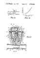
- FIG. 2 is a longitudinal cross section of apparatus constructed in accordance with the principles of this invention, depicting the condition where the valve seat seal is away from the valve seat;
- FIG. 3 is a cross section taken substantially along the line 3--3 in FIG. 2, depicting the condition where the valve seat seal is sealingly engaged with the valve seat;
- FIG. 4 is a schematic diagram showing an application of apparatus constructed in accordance with the principles of this invention.
- FIG. 1 depicts fluid flow, in the direction shown by the arrow, through a conduit 10 having a restriction 12.
- a manifold 14 having an opening 16.
- the conduit depicted in FIG. 1A exhibits what is known as the Venturi effect whereby a pressure drop is created longitudinally along the restriction 12 so that a vacuum is in effect created at the opening 16. It has been found that the vacuum increases as a function of the square of the flow rate, as schematically depicted in FIG. 1B.
- FIGS. 2 and 3 show apparatus 18 for providing signals related to the vacuum, and accordingly related to the fluid flow rate.
- the apparatus includes a housing 20, preferably molded of a material such as glass filled nylon, which housing also includes a conduit portion 22 having tapered outwardly extending flanges 24 at both ends thereof, which flanges 24 are adapted to hold in place hoses into which the ends of the conduit portion 22 are inserted.
- the inside of the conduit portion 22 is so shaped, as with a first uniform step 26 and a second tapered step 28, that a tapered orifice member 30 may be snuggly press fit into place.
- the orifice member 30 forms a restriction to fluid flow through the conduit portion 22, the apparatus being designed for fluid flow from left to right, when viewed as in FIG. 2.
- a pressure drop with respect to the pressure of the incoming fluid is created in the annular chamber 32 formed between the outside of the orifice member 30 and the inside of the conduit portion 22.
- the housing 20 is formed with an interior chamber 34.
- the lower end of the chamber 34 is formed with a smaller interiorly threaded portion 36, at the lower end of which is a small chamber 38 which communicates with the annular chamber 32 through four relatively narrow passages 40.
- the housing 20 is also formed with an open passageway 42 therethrough which communicates between the chamber 34 and the ambient environment at the exterior of the apparatus 18.
- a ferrule 44 having an opening 46 closes the passageway 42. The size of the opening 46 determines the flow rate through the passageway 42.
- a valve seat member 48 is threadedly secured in the threaded chamber portion 36.
- the housing 20 is formed with an annular groove 50 surrounding the small chamber 38, into which is inserted an O-ring 52 for sealing purposes.
- the valve seat member 48 is formed with a stepped passageway 54 which is capped by a ferrule 56 having an opening 58. Surrounding the stepped passageway 54, the valve seat member 48 is formed with a valve seat 60.
- a guide member 62 is also threadedly secured within the portion 36 above the valve seat member 48.
- the guide member 62 illustratively has three guide fingers 64 equiangularly spaced and extending upward from the threaded portion of the guide member 62.
- the upper end of the housing 20 is formed with an upstanding wall 66 surrounding the chamber 34.
- the top of the wall 66 is formed with an outwardly extending annular shoulder 68 which itself is surrounded by a relatively short upstanding wall 70.
- a diaphragm 72 seals the chamber 34 and has its outer periphery resting on the top of the wall 66 and the shoulder 68.
- a cap 74 formed with an outwardly extending flange 76, rests on the outer periphery of the diaphragm 72 inwardly of the wall 70 of the housing 20.
- a clamping ring 78 surrounds the wall 70.
- the clamping ring 70 is rolled so that it engages the lower surface of the shoulder 68, the top edge of the wall 70 and the upper surface of the flange 76 to secure the cap 74 to the housing 20 while putting a compressive load on the diaphragm 72, to complete the sealing of the chamber 34.
- the assembly includes an actuator rod 80 having an expanded portion 82 upon the upper shoulder of which rests a first diaphragm plate 84.
- the actuator rod 80 has a further portion 86 which extends through a central opening in the first diaphragm plate 84, a central opening in the diaphragm 72 and a central opening of a second diaphragm plate 88.
- the portion 86 is internally threaded and a flag 90 has a stem portion 92 thereof threadedly secured to the rod portion 86.
- the actuator rod 80 extends through a central opening in a retainer member 94.
- the retainer member 94 is slidable along the actuator rod 80.
- a plunger 96 having internal threads is threadedly secured to external threads on the retainer 94.
- At the lower end of the plunger 96 there is formed a downwardly extending foot 98 having an enlarged region over which is snapped a resilient valve seat seal 100.
- a spring 102 surrounds the lower end of the actuator rod 80.
- the extreme lower end of the actuator rod 80 is formed with an annular groove (not shown) into which is snapped a retaining ring 104, so that the spring 102 is held between the retaining ring 104 and the retainer member 94.
- a spring 106 surrounds the guide member 62 and is held between the bottom of the chamber 34 and the lower surface of the first diaphragm plate 84 to bias the diaphragm 72 and valve seat seal 100 upwardly.
- the electrical output signal from the apparatus 18 is generated by an optical interrupter assembly with which the flag 90 cooperates.
- This assembly includes a bracket 108 secured to the inside of the cap 74, illustratively by rivets 110.
- the bracket 108 has two perpendicularly extending legs 112 to which is secured a commercially available optical interrupter module 114, illustratively by means of bolts 116 and nuts 118.
- the module 114 includes a pair of spaced apart legs 120, one of which holds a light source and the other of which holds a light detector.
- the flag 90 moves between the legs 120 so that it interrupts the light path between the source of light and the detector when it is in its upper region of travel. Accordingly, an electrical signal is generated at the terminals 122.
- the pressure under the diaphragm 72 will be lower than the pressure over the diaphragm 72 and the diaphragm 72 will move downwardly against the force of the spring 106.
- this causes the actuator rod 80 to move down, pulling with it the retainer member 94, the plunger 96 and the valve seat seal 100. Travel in this manner continues until the valve seat seal 100 contacts the valve seat 60, closing off the chamber 34 from the annular chamber 32. This condition is depicted in FIG. 3, and as shown therein the flag 90 allows light to pass between the module legs 120.
- the diaphragm 72 oscillates in relationship to the vacuum created in the annular chamber 32, which is related to the square of the fluid flow rate through the conduit 22. This oscillation of the diaphragm 72 results in a signal pulse train at the terminals 122.
- FIG. 4 illustrates in schematic form a system application of the aforedescribed apparatus to fill a container 124 with a desired amount of fluid.
- the apparatus 18 is connected so that an outlet hose 126 is fitted on the conduit 22 and empties into the container 124.
- the inlet end of the conduit 22 is connected to an inlet hose 128 which is coupled through a solenoid valve 130 to a source of fluid.
- the output signal terminals 122 of the apparatus 18 are connected via the leads 132 to an electronic volume control 134.
- the control 134 has input means 136 whereby an operator can indicate a desired volume fill level for the container 124.
- the control 136 opens the solenoid valve 130 via the control leads 138 and allows fluid to flow into the container 124.
- the control 134 then responds to the pulse signals over the leads 132 to calculate the instantaneous flow rate and integrates this flow rate with respect to time to determine the amount of fluid entering the container 124. When this equals the desired volume, the control 134 causes the solenoid valve 130 to shut off the fluid flow.
Landscapes
- Physics & Mathematics (AREA)
- Fluid Mechanics (AREA)
- General Physics & Mathematics (AREA)
- Fluid-Driven Valves (AREA)
Abstract
Description
Claims (9)
Priority Applications (2)
| Application Number | Priority Date | Filing Date | Title |
|---|---|---|---|
| US06/581,520 US4526041A (en) | 1984-02-21 | 1984-02-21 | Digital fluid flow rate sensor |
| CA000472254A CA1244862A (en) | 1984-02-21 | 1985-01-17 | Digital fluid flow rate sensor |
Applications Claiming Priority (1)
| Application Number | Priority Date | Filing Date | Title |
|---|---|---|---|
| US06/581,520 US4526041A (en) | 1984-02-21 | 1984-02-21 | Digital fluid flow rate sensor |
Publications (1)
| Publication Number | Publication Date |
|---|---|
| US4526041A true US4526041A (en) | 1985-07-02 |
Family
ID=24325513
Family Applications (1)
| Application Number | Title | Priority Date | Filing Date |
|---|---|---|---|
| US06/581,520 Expired - Fee Related US4526041A (en) | 1984-02-21 | 1984-02-21 | Digital fluid flow rate sensor |
Country Status (2)
| Country | Link |
|---|---|
| US (1) | US4526041A (en) |
| CA (1) | CA1244862A (en) |
Cited By (9)
| Publication number | Priority date | Publication date | Assignee | Title |
|---|---|---|---|---|
| US4667511A (en) * | 1984-06-13 | 1987-05-26 | Voest-Alpine Aktiengesellschaft | Fuel injector nozzle with needle lift sensor |
| US4745925A (en) * | 1986-10-06 | 1988-05-24 | Dietz Henry G | Optoelectronic inhalation sensor for monitoring inhalation and for inhalation therapy |
| US4918426A (en) * | 1988-05-02 | 1990-04-17 | Amway Corporation | Method and apparatus for sensing fluid flow volume to indicate end of filter life |
| US5377524A (en) * | 1992-06-22 | 1995-01-03 | The Regents Of The University Of Michigan | Self-testing capacitive pressure transducer and method |
| US5888381A (en) * | 1997-05-16 | 1999-03-30 | United States Filter Corporation | Water filter with pressure actuated flow monitor |
| US20040255988A1 (en) * | 2003-06-17 | 2004-12-23 | Duhack Michael R. | Method and apparatus for sensing water flow through a dishwasher including a magnetic switch |
| US20040255976A1 (en) * | 2003-06-17 | 2004-12-23 | Duhack Michael R. | Method and apparatus for sensing water flow through a dishwasher including a vacuum switch |
| US20040255977A1 (en) * | 2003-06-17 | 2004-12-23 | Slocum Laurence S. | Method and apparatus for sensing water flow through a dishwasher including a thermal sensor |
| US20150224973A1 (en) * | 2012-09-12 | 2015-08-13 | Knorr-Bremse Systeme für Schienenfahrzeuge GmbH | Pressure control valve with integrated pressure compensation function and check valve function |
Citations (5)
| Publication number | Priority date | Publication date | Assignee | Title |
|---|---|---|---|---|
| US381373A (en) * | 1888-04-17 | Apparatus for measuring the quantity of water flowing through a pipe | ||
| US1298471A (en) * | 1917-07-16 | 1919-03-25 | Gen Electric | Pressure-difference-creating device. |
| US2406181A (en) * | 1943-01-14 | 1946-08-20 | Wright Aeronautical Corp | Flowmeter |
| US2886968A (en) * | 1948-03-17 | 1959-05-19 | Rolls Royce | Devices sensitive to the ratio between fluid pressures |
| US4301685A (en) * | 1978-06-30 | 1981-11-24 | Mecilec | Digital pressure-measuring device |
-
1984
- 1984-02-21 US US06/581,520 patent/US4526041A/en not_active Expired - Fee Related
-
1985
- 1985-01-17 CA CA000472254A patent/CA1244862A/en not_active Expired
Patent Citations (5)
| Publication number | Priority date | Publication date | Assignee | Title |
|---|---|---|---|---|
| US381373A (en) * | 1888-04-17 | Apparatus for measuring the quantity of water flowing through a pipe | ||
| US1298471A (en) * | 1917-07-16 | 1919-03-25 | Gen Electric | Pressure-difference-creating device. |
| US2406181A (en) * | 1943-01-14 | 1946-08-20 | Wright Aeronautical Corp | Flowmeter |
| US2886968A (en) * | 1948-03-17 | 1959-05-19 | Rolls Royce | Devices sensitive to the ratio between fluid pressures |
| US4301685A (en) * | 1978-06-30 | 1981-11-24 | Mecilec | Digital pressure-measuring device |
Cited By (12)
| Publication number | Priority date | Publication date | Assignee | Title |
|---|---|---|---|---|
| US4667511A (en) * | 1984-06-13 | 1987-05-26 | Voest-Alpine Aktiengesellschaft | Fuel injector nozzle with needle lift sensor |
| US4745925A (en) * | 1986-10-06 | 1988-05-24 | Dietz Henry G | Optoelectronic inhalation sensor for monitoring inhalation and for inhalation therapy |
| US4918426A (en) * | 1988-05-02 | 1990-04-17 | Amway Corporation | Method and apparatus for sensing fluid flow volume to indicate end of filter life |
| US5377524A (en) * | 1992-06-22 | 1995-01-03 | The Regents Of The University Of Michigan | Self-testing capacitive pressure transducer and method |
| US5888381A (en) * | 1997-05-16 | 1999-03-30 | United States Filter Corporation | Water filter with pressure actuated flow monitor |
| US20040255988A1 (en) * | 2003-06-17 | 2004-12-23 | Duhack Michael R. | Method and apparatus for sensing water flow through a dishwasher including a magnetic switch |
| US20040255976A1 (en) * | 2003-06-17 | 2004-12-23 | Duhack Michael R. | Method and apparatus for sensing water flow through a dishwasher including a vacuum switch |
| US20040255977A1 (en) * | 2003-06-17 | 2004-12-23 | Slocum Laurence S. | Method and apparatus for sensing water flow through a dishwasher including a thermal sensor |
| US6939412B2 (en) | 2003-06-17 | 2005-09-06 | Emerson Electric Company | Method and apparatus for sensing water flow through a dishwasher including a thermal sensor |
| US7163590B2 (en) | 2003-06-17 | 2007-01-16 | Emerson Electric Co. | Method and apparatus for sensing water flow through a dishwasher including a vacuum switch |
| US20150224973A1 (en) * | 2012-09-12 | 2015-08-13 | Knorr-Bremse Systeme für Schienenfahrzeuge GmbH | Pressure control valve with integrated pressure compensation function and check valve function |
| US9956944B2 (en) * | 2012-09-12 | 2018-05-01 | Knorr-Bremse Systeme für Schienenfahrzeuge GmbH | Pressure control valve with integrated pressure compensation function and check valve function |
Also Published As
| Publication number | Publication date |
|---|---|
| CA1244862A (en) | 1988-11-15 |
Similar Documents
| Publication | Publication Date | Title |
|---|---|---|
| US4526041A (en) | Digital fluid flow rate sensor | |
| US4011884A (en) | Liquid-level valving device particularly useful as automatic relief valve | |
| US3910300A (en) | Tensiometer and automatic irrigation control system utilizing same | |
| US5950923A (en) | Suck back valve | |
| US3195556A (en) | Pressure relief valve for controlling pump | |
| WO1993001433A1 (en) | Valve arrangement | |
| US4031930A (en) | Automatic shut-off nozzle with lockable vapor relief valve | |
| KR100376127B1 (en) | Suck Back Valve | |
| WO2001009696A1 (en) | Pressure control device for a pipeline | |
| KR101277693B1 (en) | Fluid flow control valve | |
| US4203462A (en) | Water level control system | |
| EP0100666B1 (en) | Liquid level control device | |
| US4444222A (en) | Automatic liquid-supply stopper plug | |
| US3527267A (en) | Automatic container filling apparatus | |
| KR20200013579A (en) | Bypass and pressure adjustment valve | |
| US2730591A (en) | Sump pump control | |
| US4898204A (en) | Low pressure gas regulator | |
| US2988099A (en) | Fluid-operated control device | |
| US5931384A (en) | Suck back valve | |
| US4352372A (en) | Precision flow control device | |
| KR100555987B1 (en) | Double float valve | |
| EP0092779B1 (en) | Miniature gas chromatograph apparatus | |
| US4721128A (en) | Safety Shutoff Valve--electromechanical | |
| US4332275A (en) | Precision flow control device | |
| US3575203A (en) | Pressure regulator device |
Legal Events
| Date | Code | Title | Description |
|---|---|---|---|
| AS | Assignment |
Owner name: SINGER COMPANY THE, EIGHT STAMFORD FORUM, STAMFORD Free format text: ASSIGNMENT OF ASSIGNORS INTEREST.;ASSIGNORS:BELLER, WILBERT E.;MATEJA, EDWARD J.;REEL/FRAME:004244/0998 Effective date: 19840209 |
|
| AS | Assignment |
Owner name: EATON CORPORATION, EATON CENTER, CLEVELAND, OH 44 Free format text: ASSIGNMENT OF ASSIGNORS INTEREST.;ASSIGNOR:SINGER COMPANY, THE;REEL/FRAME:004699/0362 Effective date: 19870320 Owner name: EATON CORPORATION, A CORP. OF OH,OHIO Free format text: ASSIGNMENT OF ASSIGNORS INTEREST;ASSIGNOR:SINGER COMPANY, THE;REEL/FRAME:004699/0362 Effective date: 19870320 |
|
| REMI | Maintenance fee reminder mailed | ||
| LAPS | Lapse for failure to pay maintenance fees | ||
| STCH | Information on status: patent discontinuation |
Free format text: PATENT EXPIRED DUE TO NONPAYMENT OF MAINTENANCE FEES UNDER 37 CFR 1.362 |
|
| FP | Lapsed due to failure to pay maintenance fee |
Effective date: 19890702 |
|
| AS | Assignment |
Owner name: EATON CORPORATION, OHIO Free format text: MERGER;ASSIGNOR:CONTROLS COMPANY OF AMERICA;REEL/FRAME:008783/0060 Effective date: 19860912 |