US4525989A - Floating foot shield for walk-behind mower with sulky - Google Patents
Floating foot shield for walk-behind mower with sulky Download PDFInfo
- Publication number
- US4525989A US4525989A US06/518,818 US51881883A US4525989A US 4525989 A US4525989 A US 4525989A US 51881883 A US51881883 A US 51881883A US 4525989 A US4525989 A US 4525989A
- Authority
- US
- United States
- Prior art keywords
- deck
- side shield
- mower
- sulky
- combination
- Prior art date
- Legal status (The legal status is an assumption and is not a legal conclusion. Google has not performed a legal analysis and makes no representation as to the accuracy of the status listed.)
- Expired - Fee Related
Links
Images

Classifications
-
- A—HUMAN NECESSITIES
- A01—AGRICULTURE; FORESTRY; ANIMAL HUSBANDRY; HUNTING; TRAPPING; FISHING
- A01D—HARVESTING; MOWING
- A01D34/00—Mowers; Mowing apparatus of harvesters
- A01D34/01—Mowers; Mowing apparatus of harvesters characterised by features relating to the type of cutting apparatus
- A01D34/412—Mowers; Mowing apparatus of harvesters characterised by features relating to the type of cutting apparatus having rotating cutters
- A01D34/63—Mowers; Mowing apparatus of harvesters characterised by features relating to the type of cutting apparatus having rotating cutters having cutters rotating about a vertical axis
- A01D34/64—Mowers; Mowing apparatus of harvesters characterised by features relating to the type of cutting apparatus having rotating cutters having cutters rotating about a vertical axis mounted on a vehicle, e.g. a tractor, or drawn by an animal or a vehicle
-
- A—HUMAN NECESSITIES
- A01—AGRICULTURE; FORESTRY; ANIMAL HUSBANDRY; HUNTING; TRAPPING; FISHING
- A01D—HARVESTING; MOWING
- A01D34/00—Mowers; Mowing apparatus of harvesters
- A01D34/01—Mowers; Mowing apparatus of harvesters characterised by features relating to the type of cutting apparatus
- A01D34/412—Mowers; Mowing apparatus of harvesters characterised by features relating to the type of cutting apparatus having rotating cutters
- A01D34/63—Mowers; Mowing apparatus of harvesters characterised by features relating to the type of cutting apparatus having rotating cutters having cutters rotating about a vertical axis
- A01D34/82—Other details
- A01D34/828—Safety devices
-
- A—HUMAN NECESSITIES
- A01—AGRICULTURE; FORESTRY; ANIMAL HUSBANDRY; HUNTING; TRAPPING; FISHING
- A01D—HARVESTING; MOWING
- A01D2101/00—Lawn-mowers
-
- F—MECHANICAL ENGINEERING; LIGHTING; HEATING; WEAPONS; BLASTING
- F02—COMBUSTION ENGINES; HOT-GAS OR COMBUSTION-PRODUCT ENGINE PLANTS
- F02B—INTERNAL-COMBUSTION PISTON ENGINES; COMBUSTION ENGINES IN GENERAL
- F02B75/00—Other engines
- F02B75/02—Engines characterised by their cycles, e.g. six-stroke
- F02B2075/022—Engines characterised by their cycles, e.g. six-stroke having less than six strokes per cycle
- F02B2075/027—Engines characterised by their cycles, e.g. six-stroke having less than six strokes per cycle four
Definitions
- the present invention relates to power-operated lawn mowing machines, and more particularly, to articulated riding mowers of the type that include a walk-behind push mower.
- riding mowers are commonly used to reduce both the amount of time and effort required for mowing.
- Riding mowers are relatively expensive.
- riding mowers are quite efficient for mowing open areas of the lawn, they frequently are not easily maneuverable about obstacles, such as trees, bushes, fences and the like.
- a person will often utilize a walk-behind push mower to mow around them, such mowers being more maneuverable in tight spaces than a typical riding mower, while using a riding mower on the remainder of the lawn.
- wheels of the sulky unit are capable of being driven only so that the riding mower will travel in a forward direction.
- the operator In the course of maneuvering the mower, it is not uncommon for the operator to desire to travel in a reverse direction. In such situations, the operator, while remaining seated on the sulky, will disengage the clutch to put the riding mower in neutral. The operator then will typically place his feet on the ground and push backwards with his legs to reverse the direction of the mower. If the operator's feet should slip while pushing the mower backwards, it is possible that his feet could slide under the mower housing and be exposed to the rotating mower blade, creating an unsafe condition.
- a foot shield for use in a walk-behind mower, and particularly a walk-behind mower having a rearward sulky attachment, for preventing the feet of the operator from sliding under the mower housing when the mower is pulled in a reverse direction.
- Another object is to provide such a foot shield which will effectively function even when irregularities in the mowing surface are encountered.
- a further object is to provide such a foot shield which adjusts automatically to take into account adjustments in the height of the mower wheels.
- FIG. 1 is a perspective of an illustrative articulated riding mower embodying the present invention
- FIG. 2 is an enlarged fragmentary, exploded perspective showing the means for attaching the sulky to the walk-behind mower and the power transmission means for driving the sulky;
- FIG. 3 is a vertical section taken in the plane of line 3--3 in FIG. 2;
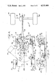
- FIG. 4 is a plan view of the illustrated riding mower showing the power transmission means for driving the sulky and the location of the attachment point of the sulky to the walk-behind mower;
- FIG. 5 is a vertical section taken in the plane of line 5--5 of FIG. 4.
- an illustrative articulated riding mower 10 embodying the present invention comprising a conventional walk-behind mower 11 with a sulky unit 12 detachably connected thereto by means of a pivotal connector 13.
- the walk-behind mower 11 includes a mower deck 14 having an inverted pan-shaped housing defining a central space, the mower deck being supported for rolling movement by two pairs of ground-engaging wheels 15, 16 located at the front and rear corner positions of the deck and mounted on axles 15a and 16a, respectively.
- Mounted on the top of the deck 14 is a rotary power source 18, typically a 4-cycle gasoline-powered internal combustion engine of about 5 horsepower.
- the engine 18 includes a shaft 19 (FIG.
- wheel adjusting brackets 17 are interposed between the wheels 15, 16 and the mower deck 14.
- Each bracket 17 includes a cooperating height adjusting lever 17a and an axle arm 17b for carrying the wheel axle, which function in a manner to change the position of the wheel axles.
- a handle 21 is secured to the mower deck 14 adjacent the rear wheels 16 and extends upwardly and rearwardly therefrom.
- the handle 21 comprises a lower portion 22 and an upper portion 24 which when the walk-behind mower 11 is being used in conjunction with the detachable sulky 12, are secured together as shown in FIG. 1 by the handle knobs 25 and shoulder bolts 26. Construction of the handle 21 in two portions facilitates the extension of the handle when the walk-behind mower 11 is used as a push mower.
- the lower handle 22 carries an engine throttle control 28 and its cooperating cable 29 for selectively controlling the speed of the engine 18, while the upper handle 24 supports a control 30 and associated cable 31 for selectively engaging an appropriate blade clutch and blade brake (not shown).
- the control 30, preferably is a "dead-man's" control of a known type, and is biased to disengage the brake clutch and apply the blade brake if no external force is applied to the control.
- a control bar 32 associated with the control 30 To engage the blade clutch and rotate the blade 20, a control bar 32 associated with the control 30 must be depressed so as to lie alongside the cross bar of the upper handle 24.
- the sulky unit 12 is pivotally attached in rearwardly extending relation to the walk-behind mower 11.
- the sulky 12 is supported for rolling movement by a pair of ground wheels 34 mounted on an axle 35 and includes a frame, generally designated 36, comprising a top support plate 37, fenders 38, side plates 39 and foot rests 40.
- An operator's seat 41 is secured to the frame 36 by means of a resilient bracket 42.
- power transmission means are provided between the engine 18 and the sulky axle 35.
- the engine 18 rotatably drives a power take-off shaft 43 (FIG. 4) which carries a pulley 44.
- a vertical jackshaft 45 mounted in upstanding relation to the mower deck between the rear wheels 16 is a vertical jackshaft 45 which rotatably supports a unitary dual pulley assembly 46 having a relatively large primary or input pulley 48 and a smaller secondary or output pulley 49, both disposed in horizontal planes for rotation about the vertical jackshaft axis.
- a primary drive V-belt 50 operatively connects the power take-off pulley 45 with the primary pulley 48.
- a backside idler pivotally mounted on the mower deck 14 includes an idler arm 51 having an idler pulley 52 mounted for rotation on the end thereof.
- the idler arm 51 is biased by a spring 54 so that the idler pulley 52 exerts a force on the primary drive belt 50 of a sufficient magnitude to maintain the drive belt 50 in tension to engage the pulleys 45, 48 and prevent slippage.
- the secondary pulley 49 is operatively connected to a pulley 55 on the sulky axle 35 by means of a secondary or sulky drive V-belt 58.
- the sulky drive belt 58 is twisted 90° in order to engage both the horizontally disposed secondary pulley 49 and the vertically disposed sulky pulley 55.
- an idler arm and pulley arrangement (not shown) similar to the backside idler discussed above may be provided.
- the operator may selectively tension the sulky drive belt 58 with such an idler pulley arrangement by means of an appropriate foot-actuated clutch pedal 59 operatively connected to the idler arm and hinged to the forward end of the foot rest 40.
- the axle 35 may include a brake drum 60 about which a brake band (not shown) is disposed.
- a brake band can be selectively tensioned by means of an appropriate brake lever 61 which extends upwardly through the top plate 37 of the sulky frame 36 so as to be readily accessible to the operator.
- the brake lever 61 may be locked in place by means of a keeper 62 which is pivotally mounted to the top plate 37, thus permitting the brake to be used as a parking brake.
- the mower deck 14 is provided with a bridge support to which the sulky support 37 is pivotally connected.
- the bridge support 70 includes a central portion 71 which overrides the rear apron of the mower deck 14 and extends horizontally between the rear corner positions of the deck overlying the unitary pulley assembly 46 of the power transmission means.
- the bridge support 70 has integrally-formed downward extensions 72 with first vertically depending sections 73, outwardly depending sections 74, and second vertically depending sections 75.
- the second vertically depending sections 75 correspond to the rear corner positions of the mower deck and are rigidly fastened thereto by means of bolts which extend through apertures 76 in the sections 75 and cooperating apertures in the mower deck.
- the rear wheels 16 are also carried by the sections 75, thus transferring much of the sulky reactive force directly from the sulky, through the support and to the wheels, thus minimizing the force exerted on the mower deck.
- the central portion 71 carries the pivotal connecter 13 and also includes a horizontal middle section 78 and inclined transition sections 79 intermediate of the middle section and the downward extensions 72.
- the lower end of the handle 21 is connected directly to the bridge support 70 so that such forces developed in the handle incident to guiding the mower are transferred directly to the bridge support and thence to the wheels, thus bypassing the mower deck.
- the lower end of the lower handle 22 is bolted to the first vertically depending section 73 of the bridge support 70, with a handle brace 80 being interposed between each end of the lower handle 22 and the bridge support 70 to provide for adjustment of the angle the handle makes with respect to the mower deck, as well as insuring a rigid connection of the handle to the bridge support.
- the central portion 71 of the bridge support 70 includes a bearing which cooperates with a pin assembly on the top support plate 37 of the sulky 12.
- a bearing 80 is mounted to the horizontal middle section 78 of the bridge support 70 through its integral flange 80a by means of two bolts, flat washers and lock nuts, 81, 82 and 84 respectively.
- the bearing 80 supports a spacer 85 having a bore therethrough and secured to the bearing 80 by means of an E-ring 86.
- the top plate 37 of the sulky 12 includes a bracket assembly 88 secured thereto by two bolts, lock washers and flat washers 89, 90 and 91 respectively.
- the bracket assembly 88 has a bore therethrough which aligns with the bore in the spacer 85 to allow the insertion of a pin assembly 92 therethrough.
- the pin assembly includes a spring-loaded plunger 94 and ball detents 95 which cooperate in a well-known manner to pivotally secure the sulky 12 to the bridge support 70.
- the pin assembly also carries, by means of a lanyard 96, an ignition key 98 needed for starting the mower.
- the sulky drive belt 58 will exert a moment on the forward, walk-behind mower 11 in a direction opposite to the rotation of the secondary pulley.
- the sulky drive belt 58 exerts a clockwise reaction moment on the walk-behind mower 11 about the axis of the jackshaft 45, tending to turn the mower to the right, when viewed from behind the mower.
- the vertical axis of the pivotal connection 13 between the walk-behind mower 11 and the sulky 12 is laterally offset from the longitudinal centerline of the walk-behind mower so that the reactive force exerted on the walk-behind mower through the pivotal connector by the propelled sulky counteracts the turning moment generated by the rotating secondary pulley to allow the riding mower, even when unguided by an operator, to travel in a substantially straight line.
- the front and rear wheels 15, 16 define a longitudinal centerline X, which the bridge support 70 overlies, and a transverse centerline Y.
- centerlines X, Y intersect at an origin O which, in the illustrated mower, is coincident with the vertical axis of the engine shaft 19.
- the reactive moment is clockwise about the jackshaft axis.
- the vertical axis of the pivotal connector 13 is disposed, when viewed from above and behind the mower, to the right of the longitudinal centerline X by an angle ⁇ , which is measured from the origin O with respect to longitudinal center line X, creating an offset from the centerline of a distance A.
- the vertical axis of the output pulley 49 is located on the mower deck 14 so as to be coincident with the vertical axis of the pivotal connector 13.
- Such undue stretching or relaxing of the sulky drive belt 58 would otherwise occur as the distance between the point on the sulky axle 35 to which the pulley 55 is attached and the vertical axis of the secondary pulley 49 would vary as the articulated mower is steered between straight and curved paths.
- a floating foot shield is provided which lies between the bottom edge of the mower deck and ground level to prevent the operator's feet from sliding under the side of the mower deck.
- the side shield automatically compensates for minor irregularities in the surface to be mowed and also adjusts automatically with the adjustment of the height of the mower deck above the ground.
- a side shield 100 comprising a metal bar is associated with the lefthand or non-discharge side of the illustrated walk-behind mower.
- the side shield 100 extends fore and aft along the lefthand side of the mower generally following the curvature of the deck and hanging from the housing between ground level and the lower edge of the deck side wall.
- the illustrated side shield 100 has a substantially horizontal central portion 104, an upwardly extending forward end 105 and an upwardly extending rearward end 106.
- the rearward end 106 is pivotally attached to the axle 16a of the rear wheel 16 by means of an integral bracket 108 having an operature therein through which the axle extends.
- the upwardly extending end 105 passes through a bracket 109 integral with the side wall of the mower deck adjacent to and rearward from the front wheel 15.
- the forward end 105 extends through a slot 110 in the mounting bracket 109.
- the slot 110 is of a width greater than the thickness of the upwardly extending end 105 of the side shield.
- the end 105 includes a collar 111 and cotter pin 112.
- the slot 110 extends in the fore and aft direction. The side shield 100 can thus adjust for lost motion by sliding horizontally in the slot 110.
- the side shield 100 In operation, upon encountering a protrusion or the like in the mowing surface, the side shield 100 will pivot about the wheel axis 16a and the forward end 105 of the side shield 100 will travel upward through the slot 110 in the mounting bracket 109. If a dip should be encountered, the side shield 100 will pivot downwardly until either the ground is encountered or the collar 111 and cotter pin 112 act to prevent further withdrawal of the forward end 105 through the slot 110 in the mounting bracket 109. It will be apparent that at all times, whether mowing a flat and level surface or an irregular surface, the foot shield acts to provide an effective barrier between the operator's feet and the mower blade.
- the articulated riding mower of the present invention is adapted for relatively easy usage and longer life than heretofore provided by previous articulated mowers.
Landscapes
- Life Sciences & Earth Sciences (AREA)
- Environmental Sciences (AREA)
- Harvester Elements (AREA)
Abstract
Description
Claims (15)
Priority Applications (1)
| Application Number | Priority Date | Filing Date | Title |
|---|---|---|---|
| US06/518,818 US4525989A (en) | 1983-08-01 | 1983-08-01 | Floating foot shield for walk-behind mower with sulky |
Applications Claiming Priority (1)
| Application Number | Priority Date | Filing Date | Title |
|---|---|---|---|
| US06/518,818 US4525989A (en) | 1983-08-01 | 1983-08-01 | Floating foot shield for walk-behind mower with sulky |
Publications (1)
| Publication Number | Publication Date |
|---|---|
| US4525989A true US4525989A (en) | 1985-07-02 |
Family
ID=24065628
Family Applications (1)
| Application Number | Title | Priority Date | Filing Date |
|---|---|---|---|
| US06/518,818 Expired - Fee Related US4525989A (en) | 1983-08-01 | 1983-08-01 | Floating foot shield for walk-behind mower with sulky |
Country Status (1)
| Country | Link |
|---|---|
| US (1) | US4525989A (en) |
Cited By (8)
| Publication number | Priority date | Publication date | Assignee | Title |
|---|---|---|---|---|
| US4783914A (en) * | 1986-11-04 | 1988-11-15 | Limbco, Inc. | Stump remover |
| US7013626B1 (en) * | 2003-07-18 | 2006-03-21 | Auburn Consolidated Industries, Inc. | Walk behind mower |
| US20070107404A1 (en) * | 2005-11-03 | 2007-05-17 | Agri-Fab, Inc. | Height adjustment system for a lawn maintenance device |
| US20110078990A1 (en) * | 2009-10-01 | 2011-04-07 | Tommy Joe Vachal | Wheel mounting/height adjustment mechanism and power equipment unit incorporating same |
| US8887480B2 (en) * | 2011-12-06 | 2014-11-18 | The Toro Company | Walk power mower with height of cut adjustment system having spring arm with replaceable locking pin |
| US20180279548A1 (en) * | 2015-10-14 | 2018-10-04 | The Toro Company | Walk reel mower |
| US20190300037A1 (en) * | 2018-04-03 | 2019-10-03 | GPS, Inc. | Pallet truck wheel assembly toe guard |
| CN111492805A (en) * | 2019-01-31 | 2020-08-07 | 创科无线普通合伙 | Power tool with variable height or speed |
Citations (10)
| Publication number | Priority date | Publication date | Assignee | Title |
|---|---|---|---|---|
| US2514407A (en) * | 1947-06-17 | 1950-07-11 | Joseph L May | Mower |
| US2919756A (en) * | 1956-03-02 | 1960-01-05 | Earl A Knipe | Riding mower |
| US2929186A (en) * | 1958-11-18 | 1960-03-22 | John H Bundy | Rotary power lawn mower guard |
| US2977739A (en) * | 1957-07-25 | 1961-04-04 | Lustyan John | Rotary lawn mower construction |
| US3032957A (en) * | 1959-12-30 | 1962-05-08 | Boyer Martin | Automatic rotary lawn mower |
| FI34188A (en) * | 1959-09-11 | 1964-05-11 | Nymanbolagen Ab | Anordning vid gräsklippare |
| US3465505A (en) * | 1968-03-18 | 1969-09-09 | Alvern J Krinke | Lawnmower |
| US4172351A (en) * | 1978-06-26 | 1979-10-30 | Roper Corporation | Safety shield construction for rotary mower |
| GB2054333A (en) * | 1979-07-31 | 1981-02-18 | Firth Cleveland Ltd | Mowing machine |
| US4300334A (en) * | 1980-02-04 | 1981-11-17 | Outboard Marine Corporation | Power rake foot guard |
-
1983
- 1983-08-01 US US06/518,818 patent/US4525989A/en not_active Expired - Fee Related
Patent Citations (10)
| Publication number | Priority date | Publication date | Assignee | Title |
|---|---|---|---|---|
| US2514407A (en) * | 1947-06-17 | 1950-07-11 | Joseph L May | Mower |
| US2919756A (en) * | 1956-03-02 | 1960-01-05 | Earl A Knipe | Riding mower |
| US2977739A (en) * | 1957-07-25 | 1961-04-04 | Lustyan John | Rotary lawn mower construction |
| US2929186A (en) * | 1958-11-18 | 1960-03-22 | John H Bundy | Rotary power lawn mower guard |
| FI34188A (en) * | 1959-09-11 | 1964-05-11 | Nymanbolagen Ab | Anordning vid gräsklippare |
| US3032957A (en) * | 1959-12-30 | 1962-05-08 | Boyer Martin | Automatic rotary lawn mower |
| US3465505A (en) * | 1968-03-18 | 1969-09-09 | Alvern J Krinke | Lawnmower |
| US4172351A (en) * | 1978-06-26 | 1979-10-30 | Roper Corporation | Safety shield construction for rotary mower |
| GB2054333A (en) * | 1979-07-31 | 1981-02-18 | Firth Cleveland Ltd | Mowing machine |
| US4300334A (en) * | 1980-02-04 | 1981-11-17 | Outboard Marine Corporation | Power rake foot guard |
Cited By (12)
| Publication number | Priority date | Publication date | Assignee | Title |
|---|---|---|---|---|
| US4783914A (en) * | 1986-11-04 | 1988-11-15 | Limbco, Inc. | Stump remover |
| US7013626B1 (en) * | 2003-07-18 | 2006-03-21 | Auburn Consolidated Industries, Inc. | Walk behind mower |
| US20070107404A1 (en) * | 2005-11-03 | 2007-05-17 | Agri-Fab, Inc. | Height adjustment system for a lawn maintenance device |
| US20110078990A1 (en) * | 2009-10-01 | 2011-04-07 | Tommy Joe Vachal | Wheel mounting/height adjustment mechanism and power equipment unit incorporating same |
| US7958943B2 (en) * | 2009-10-01 | 2011-06-14 | Exmark Manufacturing Company, Incorporated | Wheel mounting/height adjustment mechanism for a power equipment unit |
| US8887480B2 (en) * | 2011-12-06 | 2014-11-18 | The Toro Company | Walk power mower with height of cut adjustment system having spring arm with replaceable locking pin |
| US20180279548A1 (en) * | 2015-10-14 | 2018-10-04 | The Toro Company | Walk reel mower |
| US10959372B2 (en) * | 2015-10-14 | 2021-03-30 | The Toro Company | Fixed head walk reel mower with a pivotally adjustable traction drum having different mowing positions |
| US12022771B2 (en) | 2015-10-14 | 2024-07-02 | The Toro Company | Walk reel mower with pivotal shield |
| US20190300037A1 (en) * | 2018-04-03 | 2019-10-03 | GPS, Inc. | Pallet truck wheel assembly toe guard |
| US10850759B2 (en) * | 2018-04-03 | 2020-12-01 | GPS, Inc. | Pallet truck wheel assembly toe guard |
| CN111492805A (en) * | 2019-01-31 | 2020-08-07 | 创科无线普通合伙 | Power tool with variable height or speed |
Similar Documents
| Publication | Publication Date | Title |
|---|---|---|
| US5042238A (en) | Riding lawn mower | |
| US5915487A (en) | Walk-behind traction vehicle having variable speed friction drive transmission | |
| US7607283B2 (en) | Lawn mower with deck lift system and/or pump lock-out system | |
| US5865020A (en) | Lawn mower having a low center of gravity | |
| US5809755A (en) | Power mower with riding platform for supporting standing operator | |
| US4395865A (en) | Self propelled lawn mower | |
| US4429515A (en) | Self propelled lawn mower | |
| US5337543A (en) | Lawn mower for use both as riding and walking operator type | |
| US20010001170A1 (en) | Power mower with stand-on and sit-down modes | |
| US5156218A (en) | Landscape edging attachment | |
| US4514967A (en) | Bridge support for securing sulky to walk-behind mower | |
| US6668529B2 (en) | Operator control system for self-propelled vehicles | |
| US4525989A (en) | Floating foot shield for walk-behind mower with sulky | |
| US4263977A (en) | Carrier vehicle for a motor-driven rotary mower | |
| US20020078672A1 (en) | Belly mower particularly for an ATV type vehicle | |
| US2705393A (en) | Power mower | |
| US6868657B2 (en) | Mowing machines with ergonomic hand control levers | |
| EP2989880B1 (en) | Cutting deck height adjustment assembly | |
| US2855060A (en) | Tractor and sulky attachment therefor | |
| CA1138654A (en) | Power rake foot guard | |
| US20230172103A1 (en) | Storage lock assembly for lawn mower, zero-turn-radius lawn mower including same, and lawn mower | |
| US5277017A (en) | Cutting deck-mounted transformer unit for converting walk behind mid-size rotary mower into riding mower | |
| US20040113388A1 (en) | Vehicle having adjustable footrest apparatus | |
| US2842927A (en) | Automotive rideable mowing machine | |
| US6233912B1 (en) | Implement deck that shifts laterally from side to side |
Legal Events
| Date | Code | Title | Description |
|---|---|---|---|
| AS | Assignment |
Owner name: ROPER CORPORATION, KANKAKEE, ILL. AN ILL CORP. Free format text: ASSIGNMENT OF ASSIGNORS INTEREST.;ASSIGNORS:LANE, JOSEPH J.;SCANLAND, JOSEPH E.;REEL/FRAME:004173/0181 Effective date: 19830728 |
|
| FEPP | Fee payment procedure |
Free format text: PAYOR NUMBER ASSIGNED (ORIGINAL EVENT CODE: ASPN); ENTITY STATUS OF PATENT OWNER: LARGE ENTITY |
|
| FPAY | Fee payment |
Year of fee payment: 4 |
|
| FEPP | Fee payment procedure |
Free format text: PAYOR NUMBER ASSIGNED (ORIGINAL EVENT CODE: ASPN); ENTITY STATUS OF PATENT OWNER: LARGE ENTITY Free format text: PAYER NUMBER DE-ASSIGNED (ORIGINAL EVENT CODE: RMPN); ENTITY STATUS OF PATENT OWNER: LARGE ENTITY |
|
| AS | Assignment |
Owner name: AMERICAN YARD PRODUCTS, INC., STATELESS Free format text: CHANGE OF NAME;ASSIGNOR:ROPER CORPORATION, (CHANGED INTO);REEL/FRAME:005060/0135 Effective date: 19881230 |
|
| REMI | Maintenance fee reminder mailed | ||
| LAPS | Lapse for failure to pay maintenance fees | ||
| FP | Lapsed due to failure to pay maintenance fee |
Effective date: 19930704 |
|
| STCH | Information on status: patent discontinuation |
Free format text: PATENT EXPIRED DUE TO NONPAYMENT OF MAINTENANCE FEES UNDER 37 CFR 1.362 |