US4520775A - Intake system for multiple valve type engine - Google Patents
Intake system for multiple valve type engine Download PDFInfo
- Publication number
- US4520775A US4520775A US06/322,768 US32276881A US4520775A US 4520775 A US4520775 A US 4520775A US 32276881 A US32276881 A US 32276881A US 4520775 A US4520775 A US 4520775A
- Authority
- US
- United States
- Prior art keywords
- intake
- passages
- induction system
- throttle valve
- set forth
- Prior art date
- Legal status (The legal status is an assumption and is not a legal conclusion. Google has not performed a legal analysis and makes no representation as to the accuracy of the status listed.)
- Expired - Lifetime
Links
Images


Classifications
-
- F—MECHANICAL ENGINEERING; LIGHTING; HEATING; WEAPONS; BLASTING
- F02—COMBUSTION ENGINES; HOT-GAS OR COMBUSTION-PRODUCT ENGINE PLANTS
- F02M—SUPPLYING COMBUSTION ENGINES IN GENERAL WITH COMBUSTIBLE MIXTURES OR CONSTITUENTS THEREOF
- F02M35/00—Combustion-air cleaners, air intakes, intake silencers, or induction systems specially adapted for, or arranged on, internal-combustion engines
- F02M35/10—Air intakes; Induction systems
- F02M35/10242—Devices or means connected to or integrated into air intakes; Air intakes combined with other engine or vehicle parts
- F02M35/10308—Equalizing conduits, e.g. between intake ducts or between plenum chambers
-
- F—MECHANICAL ENGINEERING; LIGHTING; HEATING; WEAPONS; BLASTING
- F02—COMBUSTION ENGINES; HOT-GAS OR COMBUSTION-PRODUCT ENGINE PLANTS
- F02B—INTERNAL-COMBUSTION PISTON ENGINES; COMBUSTION ENGINES IN GENERAL
- F02B31/00—Modifying induction systems for imparting a rotation to the charge in the cylinder
- F02B31/08—Modifying induction systems for imparting a rotation to the charge in the cylinder having multiple air inlets
- F02B31/085—Modifying induction systems for imparting a rotation to the charge in the cylinder having multiple air inlets having two inlet valves
-
- F—MECHANICAL ENGINEERING; LIGHTING; HEATING; WEAPONS; BLASTING
- F02—COMBUSTION ENGINES; HOT-GAS OR COMBUSTION-PRODUCT ENGINE PLANTS
- F02F—CYLINDERS, PISTONS OR CASINGS, FOR COMBUSTION ENGINES; ARRANGEMENTS OF SEALINGS IN COMBUSTION ENGINES
- F02F1/00—Cylinders; Cylinder heads
- F02F1/24—Cylinder heads
- F02F1/42—Shape or arrangement of intake or exhaust channels in cylinder heads
- F02F1/4214—Shape or arrangement of intake or exhaust channels in cylinder heads specially adapted for four or more valves per cylinder
-
- F—MECHANICAL ENGINEERING; LIGHTING; HEATING; WEAPONS; BLASTING
- F02—COMBUSTION ENGINES; HOT-GAS OR COMBUSTION-PRODUCT ENGINE PLANTS
- F02M—SUPPLYING COMBUSTION ENGINES IN GENERAL WITH COMBUSTIBLE MIXTURES OR CONSTITUENTS THEREOF
- F02M35/00—Combustion-air cleaners, air intakes, intake silencers, or induction systems specially adapted for, or arranged on, internal-combustion engines
- F02M35/10—Air intakes; Induction systems
- F02M35/10006—Air intakes; Induction systems characterised by the position of elements of the air intake system in direction of the air intake flow, i.e. between ambient air inlet and supply to the combustion chamber
- F02M35/10072—Intake runners
-
- F—MECHANICAL ENGINEERING; LIGHTING; HEATING; WEAPONS; BLASTING
- F02—COMBUSTION ENGINES; HOT-GAS OR COMBUSTION-PRODUCT ENGINE PLANTS
- F02M—SUPPLYING COMBUSTION ENGINES IN GENERAL WITH COMBUSTIBLE MIXTURES OR CONSTITUENTS THEREOF
- F02M35/00—Combustion-air cleaners, air intakes, intake silencers, or induction systems specially adapted for, or arranged on, internal-combustion engines
- F02M35/10—Air intakes; Induction systems
- F02M35/1015—Air intakes; Induction systems characterised by the engine type
- F02M35/10183—Engines having intake ducts fed from a separate carburettor or injector, the idling system being considered as a separate carburettor
-
- F—MECHANICAL ENGINEERING; LIGHTING; HEATING; WEAPONS; BLASTING
- F02—COMBUSTION ENGINES; HOT-GAS OR COMBUSTION-PRODUCT ENGINE PLANTS
- F02M—SUPPLYING COMBUSTION ENGINES IN GENERAL WITH COMBUSTIBLE MIXTURES OR CONSTITUENTS THEREOF
- F02M35/00—Combustion-air cleaners, air intakes, intake silencers, or induction systems specially adapted for, or arranged on, internal-combustion engines
- F02M35/10—Air intakes; Induction systems
- F02M35/104—Intake manifolds
- F02M35/108—Intake manifolds with primary and secondary intake passages
- F02M35/1085—Intake manifolds with primary and secondary intake passages the combustion chamber having multiple intake valves
-
- F—MECHANICAL ENGINEERING; LIGHTING; HEATING; WEAPONS; BLASTING
- F02—COMBUSTION ENGINES; HOT-GAS OR COMBUSTION-PRODUCT ENGINE PLANTS
- F02B—INTERNAL-COMBUSTION PISTON ENGINES; COMBUSTION ENGINES IN GENERAL
- F02B2275/00—Other engines, components or details, not provided for in other groups of this subclass
- F02B2275/20—SOHC [Single overhead camshaft]
-
- Y—GENERAL TAGGING OF NEW TECHNOLOGICAL DEVELOPMENTS; GENERAL TAGGING OF CROSS-SECTIONAL TECHNOLOGIES SPANNING OVER SEVERAL SECTIONS OF THE IPC; TECHNICAL SUBJECTS COVERED BY FORMER USPC CROSS-REFERENCE ART COLLECTIONS [XRACs] AND DIGESTS
- Y02—TECHNOLOGIES OR APPLICATIONS FOR MITIGATION OR ADAPTATION AGAINST CLIMATE CHANGE
- Y02T—CLIMATE CHANGE MITIGATION TECHNOLOGIES RELATED TO TRANSPORTATION
- Y02T10/00—Road transport of goods or passengers
- Y02T10/10—Internal combustion engine [ICE] based vehicles
- Y02T10/12—Improving ICE efficiencies
Definitions
- This invention relates to an improved intake system for a multiple valve type engine and more particularly to an improved induction arrangement that provides good running throughout the engine speed and load ranges and which ensures against the accumulation of unnecessary combustion deposits in the induction passages.
- the invention relates to an improved spark plug arrangement for such an engine.
- Engines embodying multiple intake passages and throttle valves for controlling the flow so that only one of the intake passages serves the major portion of the charge requirements at low loads may have different flow conditions existing within the combustion chamber when different numbers of the intake passages are serving the chambers. That is, when only one of the intake passages is serving the chamber, a swirling pattern may be established in the combustion chamber. When both passages, however, are supplying the charge, either a non-swirling pattern may be established or a flow path in a completely different direction may exist. Thus, if only a single spark plug is employed in the combustion chamber, this plug may not be positioned at the optimum location to fire the charge under all running conditions.
- a first feature of this invention is adapted to be embodied in an induction system for an internal combustion engine of the type having a pair of intake ports serving the same chamber of the engine with separate intake passages each independently serving a respective one of the intake ports.
- Throttle valve means are provided in the intake passages for controlling the flow therethrough and means actuate the throttle valve means so that the low load condition will be served primarily through the first induction passage and the high load condition will be served through both of the induction passages.
- an interconnecting passage extends between the first and second intake passages downstream of the throttle valve means so that a portion of the idle charge requirements will be supplied through the second intake passage.
- Another feature of the invention is adapted to be embodied in an induction system for an internal combustion engine having a combustion chamber that is defined at least in part by a cylinder head, a cylinder bore and a piston.
- a pair of intake ports communicate with the combustion chamber and a pair of intake valves control the flow through the respective intake ports.
- a pair of spark plugs are provided in the combustion chamber having their terminals disposed on diametrically opposite sides of the chamber.
- FIG. 1 is a bottom plan view, with portions broken away, of the cylinder head and induction system of an engine constructed in accordance with this invention and is taken generally in the direction of the line 1--1 of FIG. 2.
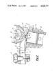
- FIG. 2 is an enlarged cross-sectional view taken through a single cylinder of the engine.
- FIG. 3 is a bottom plan view, with portions broken away, similar to FIG. 1 and shows another embodiment of the invention.
- FIG. 4 is a bottom view with portions broken away similar to FIG. 1.
- the reference numeral 11 indicates generally an internal combustion engine embodying this invention.
- the engine 11 in the illustrated embodiment is of the single cylinder type; however, it should be readily apparent to those skilled in the art that the invention may be used in conjunction with engines having a greater number of cylinders and engines of other types.
- the engine 11 includes a cylinder block 12 having a cylinder bore 13 in which a piston 14 is supported for reciprocation in a known manner.
- a cylinder head indicated generally by the reference numeral 15, is affixed to the cylinder block 12 in a known manner.
- the cylinder head 15 has a recess 16 which with the piston 14 and cylinder bore 13 forms a chamber of volume which varies as the piston 14 reciprocates.
- the cavity 16 will, at times, hereinafter be referred to as the combustion chamber.
- a pair of exhaust ports 17 are formed in one side of the cylinder head 15 and communicate with the combustion chamber 16 via exhaust valves 18 that are operated in any suitable manner, for example by means of an overhead mounted camshaft 19 and rocker arms 21.
- the exhaust valves 18 are positioned on one side of a vertically extending plane 22 (FIG. 1) that includes the axis of the cylinder bore 13.
- the cylinder head 15 On the other side of the plane 22, the cylinder head 15 is formed with a primary intake passage 23 and a secondary intake passage 24.
- the intake valves 25 are operated in unison by means of the overhead camshaft 19 via individual rocker arms 26.
- the intake valves 25 are positioned on the diametrically opposite side of the plane 22 from the exhaust valves 18.
- a staged, two barrel carburetor, indicated generally by the reference numeral 27 is provided for delivering a fuel/air charge to the intake passages 23 and 24.
- the carburetor 27 has a primary barrel 28 that is aligned with the primary intake passage 23 and a secondary barrel 29 that is aligned with the cylinder head secondary intake passage 24.
- Sliding pistons 32 and 33 are provided in the barrels 28 and 29, respectively, for controlling the size of the venturi therein and for controlling the amount of fuel discharge as is well known with this type of carburetor.
- the barrels 28 and 29 receive an intake charge of air from an air cleaner (not shown).
- a throttle valve 34 is positioned in the primary carburetor barrel 28 downstream of its sliding piston 32.
- the primary throttle valve 34 is adapted to be coupled to any suitable form of mechanical actuator that is operated by the operator.
- the primary throttle valve 34 is supported upon a primary throttle valve shaft 35 which is connected, by means of a coupling mechanism 36 to a secondary throttle valve shaft 37.
- a secondary throttle valve 38 is affixed to the secondary throttle valve shaft 37 in the carburetor barrel 29 downstream of the piston 33.
- the coupling mechanism 36 is designed so that the secondary throttle valve 38 and its shaft 37 are opened after a predetermined opening of the primary throttle valve 34.
- the secondary throttle valve 38 will be progressively opened so that both throttle valves 34 and 38 either reach their fully opened position at the same time, or so that the secondary throttle valve 38 may continue to move to its opened position once the primary throttle valve 34 is fully opened. Any of the well known linkage arrangements may be employed for this purpose.
- the construction of the engine 11 as thus far described may be considered to be conventional. With such an arrangement, the idle and low speed charge requirements for the engine will be supplied primarily through the primary intake passage 23. With previously constructed arrangements of this type, however, the lack of flow through the secondary intake passage 24 has been found to provide inadequate cooling for its associated intake valve and, furthermore, exhaust gases and solid carbon particles may be blown back into the passage 24 so as to obstruct the operation of the secondary throttle valve 38. To avoid these difficulties, a connecting passage 39 is formed in a wall 41 that divides the primary intake passage 23 from the secondary intake passage 24. The connecting passage 39 permits a portion of the intake charge from the primary intake passage 23 to flow into the secondary intake passage 24 at such times as the secondary throttle valve 38 is closed.
- the size and orientation of the connecting passage 39 may be chosen to achieve the desired cross flow between the primary intake passage 23 and the secondary intake passage 41. If desired, the connecting passage may be formed at an angle between the two intake passages 23 and 24 as shown by either FIG. 3 wherein the passage is inclined as shown by the reference numeral 42 or FIG. 4 wherein the opposite inclination is shown by the reference numeral 43.
- the connecting passage may be formed either by drilling or by casting an insert in place or in any other suitable manner.
- the intake charge will be delivered to the chamber 16 primarily through the intake valve 25 associated with the primary intake passage 23.
- a small amount of charge will also be delivered to the chamber through the connecting passageway 39 and secondary intake passage 24.
- a swirl will be generated in the intake charge as indicated by the arrow 45 in FIG. 1.
- This swirling motion will tend to cause the heavier fuel particles to be driven outwardly in the chamber so that there will be a richer fuel/air mixture at the periphery of the chamber 16 than in the center.
- a spark plug 46 is located on the plane 22 at the outer peripheral edge of the chamber 16.
- spark plugs 46 and 47 may be placed on a plane that is perpendicular to this plane as indicated by the phantom lines 48 and 49 in FIG. 1. The same good ignition will occur with this location and again it should be noted that the spark plugs 48 and 49 are positioned with their gaps at the periphery of the chamber 16.
Landscapes
- Engineering & Computer Science (AREA)
- Chemical & Material Sciences (AREA)
- Combustion & Propulsion (AREA)
- Mechanical Engineering (AREA)
- General Engineering & Computer Science (AREA)
- Control Of Throttle Valves Provided In The Intake System Or In The Exhaust System (AREA)
Abstract
Description
Claims (11)
Applications Claiming Priority (2)
| Application Number | Priority Date | Filing Date | Title |
|---|---|---|---|
| JP55163988A JPS5788246A (en) | 1980-11-20 | 1980-11-20 | Suction device for multi-valve type engine |
| JP55-163988 | 1980-11-20 |
Publications (1)
| Publication Number | Publication Date |
|---|---|
| US4520775A true US4520775A (en) | 1985-06-04 |
Family
ID=15784619
Family Applications (1)
| Application Number | Title | Priority Date | Filing Date |
|---|---|---|---|
| US06/322,768 Expired - Lifetime US4520775A (en) | 1980-11-20 | 1981-11-19 | Intake system for multiple valve type engine |
Country Status (2)
| Country | Link |
|---|---|
| US (1) | US4520775A (en) |
| JP (1) | JPS5788246A (en) |
Cited By (22)
| Publication number | Priority date | Publication date | Assignee | Title |
|---|---|---|---|---|
| US4840146A (en) * | 1987-05-11 | 1989-06-20 | Hitachi, Ltd. | Multiple throttle mechanism for internal combustion engines |
| US5005533A (en) * | 1988-12-09 | 1991-04-09 | Fuji Jukogyo Kabushiki Kaisha | Two cycle engine with fuel injector |
| US5007387A (en) * | 1990-01-29 | 1991-04-16 | Masachika Arao | Four valve per cylinder engine head |
| US5190007A (en) * | 1991-01-31 | 1993-03-02 | Jaguar Cars Limited | Air induction system for an internal combustion engine |
| FR2690713A1 (en) * | 1992-04-30 | 1993-11-05 | Renault | Intake device for internal combustion engine. |
| US5950582A (en) * | 1998-06-08 | 1999-09-14 | Ford Global Technologies, Inc. | Internal combustion engine with variable camshaft timing and intake valve masking |
| US5957096A (en) * | 1998-06-09 | 1999-09-28 | Ford Global Technologies, Inc. | Internal combustion engine with variable camshaft timing, charge motion control valve, and variable air/fuel ratio |
| US5960755A (en) * | 1998-06-09 | 1999-10-05 | Ford Global Technologies, Inc. | Internal combustion engine with variable camshaft timing and variable duration exhaust event |
| US6155229A (en) * | 1999-12-21 | 2000-12-05 | Ford Global Technologies, Inc. | Charge motion control valve in upper intake manifold |
| US6202626B1 (en) * | 1997-01-31 | 2001-03-20 | Yamaha Hatsudoki Kabushiki Kaisha | Engine having combustion control system |
| US6363903B1 (en) * | 1999-09-03 | 2002-04-02 | Honda Giken Kogyo Kabushiki Kaisha | Intake port structure in four-stroke cycle internal combustion engine |
| US6520146B2 (en) * | 2000-03-14 | 2003-02-18 | Avl List Gmbh | Four-stroke internal combustion engine with at least two inlet valves |
| US20060150952A1 (en) * | 2004-02-25 | 2006-07-13 | Jialin Yang | Method and apparatus for controlling operation of dual mode HCCI engines |
| US20090013955A1 (en) * | 2007-07-12 | 2009-01-15 | Brian Michael Hynes Sheridan | Manifold communication channel |
| US20090241875A1 (en) * | 2008-03-26 | 2009-10-01 | Labere Rikki Scott | Apparatus and methods for continuous variable valve timing |
| US20150233281A1 (en) * | 2014-02-18 | 2015-08-20 | Röchling Automotive SE & Co. KG | Intake Manifold with Integrated Charge Air Cooler with Two Circuits |
| US20160090951A1 (en) * | 2014-09-30 | 2016-03-31 | Hyundai Motor Company | Intake air control apparatus of engine |
| US20180258838A1 (en) * | 2016-09-01 | 2018-09-13 | Bright Acceleration Technologies LLC | Cross-port air flow to reduce pumping losses |
| FR3071885A1 (en) * | 2017-10-03 | 2019-04-05 | Renault S.A.S. | INTAKE COLLECTOR WITH REDUCED SIZE |
| US10364739B2 (en) * | 2016-09-01 | 2019-07-30 | Bright Acceleration Technologies LLC | Synergistic induction and turbocharging in internal combustion engine systems |
| US10408122B2 (en) * | 2016-09-01 | 2019-09-10 | Bright Acceleration Technologies LLC | Synergistic induction and turbocharging in internal combustion engine systems |
| US10697357B2 (en) | 2016-09-01 | 2020-06-30 | Bright Acceleration Technologies LLC | Cross-port air flow to reduce pumping losses |
Citations (9)
| Publication number | Priority date | Publication date | Assignee | Title |
|---|---|---|---|---|
| US2481890A (en) * | 1945-05-19 | 1949-09-13 | George B Fowler | Internal-combustion engine and method of operating the same |
| US3698371A (en) * | 1970-04-28 | 1972-10-17 | Toyo Kogyo Co | Surging prevention device for use in vehicle having multicylinder spark-ignition internal combustion engine |
| JPS55132356A (en) * | 1979-04-04 | 1980-10-15 | Nissan Motor Co Ltd | Fluid pressure control valve of dual pipe system |
| US4256068A (en) * | 1978-03-28 | 1981-03-17 | Honda Giken Kogyo Kabushiki Kaisha | Oblong piston and cylinder for internal combustion engine |
| US4264535A (en) * | 1978-02-24 | 1981-04-28 | Toyo Kogyo Co., Ltd. | Fuel intake system for multi-cylinder internal combustion engine |
| US4270500A (en) * | 1977-12-19 | 1981-06-02 | Nissan Motor Company, Limited | Internal combustion engine with dual induction system |
| US4271801A (en) * | 1977-10-12 | 1981-06-09 | Toyota Jidosha Kogyo Kabushiki Kaisha | Internal combustion engine with twin intake ports for each cylinder |
| US4300504A (en) * | 1978-08-10 | 1981-11-17 | Yamaha Hatsudoki Kabushiki Kaisha | Internal combustion engine |
| US4317438A (en) * | 1978-10-06 | 1982-03-02 | Honda Giken Kogyo Kabushiki Kaisha | High power output engine |
Family Cites Families (1)
| Publication number | Priority date | Publication date | Assignee | Title |
|---|---|---|---|---|
| JPS54126817A (en) * | 1978-03-24 | 1979-10-02 | Mazda Motor Corp | Intake device for multicylinder engine |
-
1980
- 1980-11-20 JP JP55163988A patent/JPS5788246A/en active Pending
-
1981
- 1981-11-19 US US06/322,768 patent/US4520775A/en not_active Expired - Lifetime
Patent Citations (9)
| Publication number | Priority date | Publication date | Assignee | Title |
|---|---|---|---|---|
| US2481890A (en) * | 1945-05-19 | 1949-09-13 | George B Fowler | Internal-combustion engine and method of operating the same |
| US3698371A (en) * | 1970-04-28 | 1972-10-17 | Toyo Kogyo Co | Surging prevention device for use in vehicle having multicylinder spark-ignition internal combustion engine |
| US4271801A (en) * | 1977-10-12 | 1981-06-09 | Toyota Jidosha Kogyo Kabushiki Kaisha | Internal combustion engine with twin intake ports for each cylinder |
| US4270500A (en) * | 1977-12-19 | 1981-06-02 | Nissan Motor Company, Limited | Internal combustion engine with dual induction system |
| US4264535A (en) * | 1978-02-24 | 1981-04-28 | Toyo Kogyo Co., Ltd. | Fuel intake system for multi-cylinder internal combustion engine |
| US4256068A (en) * | 1978-03-28 | 1981-03-17 | Honda Giken Kogyo Kabushiki Kaisha | Oblong piston and cylinder for internal combustion engine |
| US4300504A (en) * | 1978-08-10 | 1981-11-17 | Yamaha Hatsudoki Kabushiki Kaisha | Internal combustion engine |
| US4317438A (en) * | 1978-10-06 | 1982-03-02 | Honda Giken Kogyo Kabushiki Kaisha | High power output engine |
| JPS55132356A (en) * | 1979-04-04 | 1980-10-15 | Nissan Motor Co Ltd | Fluid pressure control valve of dual pipe system |
Cited By (29)
| Publication number | Priority date | Publication date | Assignee | Title |
|---|---|---|---|---|
| US4840146A (en) * | 1987-05-11 | 1989-06-20 | Hitachi, Ltd. | Multiple throttle mechanism for internal combustion engines |
| US5005533A (en) * | 1988-12-09 | 1991-04-09 | Fuji Jukogyo Kabushiki Kaisha | Two cycle engine with fuel injector |
| US5007387A (en) * | 1990-01-29 | 1991-04-16 | Masachika Arao | Four valve per cylinder engine head |
| US5190007A (en) * | 1991-01-31 | 1993-03-02 | Jaguar Cars Limited | Air induction system for an internal combustion engine |
| FR2690713A1 (en) * | 1992-04-30 | 1993-11-05 | Renault | Intake device for internal combustion engine. |
| US6202626B1 (en) * | 1997-01-31 | 2001-03-20 | Yamaha Hatsudoki Kabushiki Kaisha | Engine having combustion control system |
| US5950582A (en) * | 1998-06-08 | 1999-09-14 | Ford Global Technologies, Inc. | Internal combustion engine with variable camshaft timing and intake valve masking |
| US5957096A (en) * | 1998-06-09 | 1999-09-28 | Ford Global Technologies, Inc. | Internal combustion engine with variable camshaft timing, charge motion control valve, and variable air/fuel ratio |
| US5960755A (en) * | 1998-06-09 | 1999-10-05 | Ford Global Technologies, Inc. | Internal combustion engine with variable camshaft timing and variable duration exhaust event |
| US6363903B1 (en) * | 1999-09-03 | 2002-04-02 | Honda Giken Kogyo Kabushiki Kaisha | Intake port structure in four-stroke cycle internal combustion engine |
| US6155229A (en) * | 1999-12-21 | 2000-12-05 | Ford Global Technologies, Inc. | Charge motion control valve in upper intake manifold |
| US6520146B2 (en) * | 2000-03-14 | 2003-02-18 | Avl List Gmbh | Four-stroke internal combustion engine with at least two inlet valves |
| US20060150952A1 (en) * | 2004-02-25 | 2006-07-13 | Jialin Yang | Method and apparatus for controlling operation of dual mode HCCI engines |
| US7258104B2 (en) * | 2004-02-25 | 2007-08-21 | Ford Global Technologies, Llc | Method and apparatus for controlling operation of dual mode HCCI engines |
| US20090013955A1 (en) * | 2007-07-12 | 2009-01-15 | Brian Michael Hynes Sheridan | Manifold communication channel |
| US8468993B2 (en) * | 2007-07-12 | 2013-06-25 | Kohler Co. | Manifold communication channel |
| US20090241875A1 (en) * | 2008-03-26 | 2009-10-01 | Labere Rikki Scott | Apparatus and methods for continuous variable valve timing |
| US7866292B2 (en) | 2008-03-26 | 2011-01-11 | AES Industries Inc | Apparatus and methods for continuous variable valve timing |
| US9863327B2 (en) * | 2014-02-18 | 2018-01-09 | Röchling Automotive SE & Co. KG | Intake manifold with integrated charge air cooler with two circuits |
| US20150233281A1 (en) * | 2014-02-18 | 2015-08-20 | Röchling Automotive SE & Co. KG | Intake Manifold with Integrated Charge Air Cooler with Two Circuits |
| US20160090951A1 (en) * | 2014-09-30 | 2016-03-31 | Hyundai Motor Company | Intake air control apparatus of engine |
| US9784225B2 (en) * | 2014-09-30 | 2017-10-10 | Hyundai Motor Company | Intake air control apparatus of engine |
| US20180258838A1 (en) * | 2016-09-01 | 2018-09-13 | Bright Acceleration Technologies LLC | Cross-port air flow to reduce pumping losses |
| US10302008B2 (en) * | 2016-09-01 | 2019-05-28 | Bright Acceleration Technologies LLC | Cross-port air flow to reduce pumping losses |
| US10364739B2 (en) * | 2016-09-01 | 2019-07-30 | Bright Acceleration Technologies LLC | Synergistic induction and turbocharging in internal combustion engine systems |
| US10408122B2 (en) * | 2016-09-01 | 2019-09-10 | Bright Acceleration Technologies LLC | Synergistic induction and turbocharging in internal combustion engine systems |
| US10697357B2 (en) | 2016-09-01 | 2020-06-30 | Bright Acceleration Technologies LLC | Cross-port air flow to reduce pumping losses |
| US11022029B2 (en) | 2016-09-01 | 2021-06-01 | Bright Acceleration Technologies LLC | Cross-port air flow to reduce pumping losses |
| FR3071885A1 (en) * | 2017-10-03 | 2019-04-05 | Renault S.A.S. | INTAKE COLLECTOR WITH REDUCED SIZE |
Also Published As
| Publication number | Publication date |
|---|---|
| JPS5788246A (en) | 1982-06-02 |
Similar Documents
| Publication | Publication Date | Title |
|---|---|---|
| US4520775A (en) | Intake system for multiple valve type engine | |
| US4300504A (en) | Internal combustion engine | |
| US4617896A (en) | Internal combustion engine having three intake valves per cylinder | |
| US4576131A (en) | Intake control system for multi-valve type internal combustion engine | |
| EP0703355B1 (en) | Internal combustion engine | |
| US5063887A (en) | Exhaust control valve system for parallel multi-cylinder two-cycle engine | |
| US5018485A (en) | Intake system for automative engine | |
| US4249495A (en) | Internal combustion engine and head thereof | |
| US4765285A (en) | Intake system for internal combustion engine | |
| US4550700A (en) | Intake system for multi-intake valve type engine | |
| US5477823A (en) | Control valve for engine intake control system | |
| US4519350A (en) | Intake system for an internal combustion engine | |
| EP0321313A2 (en) | Internal combustion engine for a vehicle | |
| US5487365A (en) | Induction system for engine | |
| EP0499268A1 (en) | Multiple valve internal combustion engine | |
| US5826560A (en) | Engine combustion chamber and method of operation | |
| US4901680A (en) | Intake system for engines | |
| US4627400A (en) | Porting system for internal combustion engine | |
| US4660530A (en) | Intake system for internal combustion engine | |
| US5462027A (en) | Induction system for engine | |
| US4292944A (en) | Intake control system for internal combustion engine | |
| US5307773A (en) | Squish structure for spark ignition engine | |
| EP0610679B1 (en) | Induction system for engine | |
| US4567860A (en) | Intake system for multiple cylinder engines | |
| US5549088A (en) | Induction system for engine |
Legal Events
| Date | Code | Title | Description |
|---|---|---|---|
| AS | Assignment |
Owner name: YAMAHA HATSUDOKI KABUSHIKI KAISHA, D/B/A YAMAHA MO Free format text: ASSIGNMENT OF ASSIGNORS INTEREST.;ASSIGNOR:NAKAMURA, HARUO;REEL/FRAME:003962/0098 Effective date: 19811106 |
|
| STCF | Information on status: patent grant |
Free format text: PATENTED CASE |
|
| FEPP | Fee payment procedure |
Free format text: PAYOR NUMBER ASSIGNED (ORIGINAL EVENT CODE: ASPN); ENTITY STATUS OF PATENT OWNER: LARGE ENTITY |
|
| FPAY | Fee payment |
Year of fee payment: 4 |
|
| FPAY | Fee payment |
Year of fee payment: 8 |
|
| FEPP | Fee payment procedure |
Free format text: PAYER NUMBER DE-ASSIGNED (ORIGINAL EVENT CODE: RMPN); ENTITY STATUS OF PATENT OWNER: LARGE ENTITY Free format text: PAYOR NUMBER ASSIGNED (ORIGINAL EVENT CODE: ASPN); ENTITY STATUS OF PATENT OWNER: LARGE ENTITY |
|
| FPAY | Fee payment |
Year of fee payment: 12 |