US450423A - Feeding device for skelp-mills - Google Patents
Feeding device for skelp-mills Download PDFInfo
- Publication number
- US450423A US450423A US450423DA US450423A US 450423 A US450423 A US 450423A US 450423D A US450423D A US 450423DA US 450423 A US450423 A US 450423A
- Authority
- US
- United States
- Prior art keywords
- roll
- shaft
- feeding device
- skelp
- plate
- Prior art date
- Legal status (The legal status is an assumption and is not a legal conclusion. Google has not performed a legal analysis and makes no representation as to the accuracy of the status listed.)
- Expired - Lifetime
Links
Images

Classifications
-
- B—PERFORMING OPERATIONS; TRANSPORTING
- B65—CONVEYING; PACKING; STORING; HANDLING THIN OR FILAMENTARY MATERIAL
- B65H—HANDLING THIN OR FILAMENTARY MATERIAL, e.g. SHEETS, WEBS, CABLES
- B65H20/00—Advancing webs
- B65H20/02—Advancing webs by friction roller
Definitions
- the object of my invention is to provide a simple but efficient device for facilitating the handling of metal bars or plates in certain rolling-mill operations-for instance, in taking a bar or plate from a train of finishingrolls and feeding it forward to apair of shears or other machine in which said bar or plate is subjected to subsequent treatment.
- the invention comprises a pair of feedrolls, one of which is positively driven, the other being provided with mechanism whereby it may be moved toward or from said positively-driven roll, all as fully described hereinafter.
- Figure l is a plan view of a feeding device constructed in accordance with my invention.
- Fig. 2 is a front view of the same, looking in the direction of the arrow l, Fig. l; and
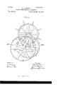
- Fig. 3 is an end view, on a larger scale, looking in the direction of the arrow 2, Fig. l. j
- A is a bed-plate, upon which are suitable bearings d for the shaft.
- b of a roll B said shaft being provided with a pulley D for receiving a driving-belt from a pulley on any adjacent counter-shaft, that portion of the shaft b beyond the pulley being adapted to a bearing a.
- the shaft F projects in one direction considerably be yond the bearings d, and is adapted to abearing g, near the base of a standard I-I, mounted on the base-plate A, the outer end of said shaft F being provided with a spur-wheel h, which meshes with a spur-pinion on a shaft J, the latter turning in a bearing lo at the upper end of the standard H, and in a similar baring la at the upper end of alike standard H', mounted upon the bed-plate A, adjacent to the standard H.
- the outer end of the shaft .I is provided with a hand-wheel K, whereby said shaft can be readily turned in either direction, such movement being transmitted through the spur-gearing to the shaft F, so that a rocking movement can be imparted to the latter shaft, and its arms f thereby vibrated, so as to carry the roll G toward and from the roll B.
- the latter roll rotates continuously, and during the rolling of the bar or plate by the train of rolls the roll G occupies aposition awayfrom the roll B, as shown, for instance, by dotted lines in Fig. 3.
- the feeding device forming the subject of my invention is, by preference, so located in respect to the rolls that as the bar or plate leaves the finishing-pass the end of the same will be projected over the roll B, and the hand-wheel K is then manipulated so as to swing the rock-shaft F and cause the roll G to move over and toward the roll B, this movement continuing until the bar or plate is firmly gripped between the rolls B and G, and is consequently fed forward, owing to the rotation of said roll B, the parts preserving this relation to each other until the feeding of the bar or strip has been completed, whereupon the roll G is again moved away from the roll B until another bar or strip has to be acted upon.
- the bed-plate A is preferably sunken beneath the floor of the mill to such an extent that the roll B proj ectsbut slightly above the floor-line of the mill, as shown, for instance, in Fig. 3.
Landscapes
- Paper (AREA)
Description
2 Sheets-Sheet 1.
(.No Model.)
T.- J. PRICE.
FBBDING DBVIGE FOR SKBLP MILLS, 50. No. 450,423. Patented Apr. 14,1891.
M` 4H l E "1 W [WWW W o I o qu Ik; l fr; f q. N S22- v 1:11@ Q3 f N .1-1. Q k. 1 Y" T:-
1 md im (No Model.) 2 Sheets-Sheet 2. T. J. PRICE.
FBEDING DEVICE FOR SKELPMILLS, &c. No. 450,423. Patented Apr. 14, 1891.
Ejem.
WI/'mss @s Iwan/Zar S max T/wmcw frica UNITED Arnivr FEEDING DEVICE FOR SKELP-lVlILLS, 840.
SPECIFICATION forming part 0f Letters Patent N0. 450,423, dated April 14, 1891. Application filed November l0, 1890. Serial No. 370,903. (No model.)
To aZZ whom it may concern.-
Be it known that I, THOMAS J. PRICE, a citizen of the United States, and a resident of Danville, Montour county, Pennsylvania, have invented certain Improvements in Feeding Devices for Skelp-Wlills, &c., of which the following is a specification.
The object of my invention is to provide a simple but efficient device for facilitating the handling of metal bars or plates in certain rolling-mill operations-for instance, in taking a bar or plate from a train of finishingrolls and feeding it forward to apair of shears or other machine in which said bar or plate is subjected to subsequent treatment.
The invention comprises a pair of feedrolls, one of which is positively driven, the other being provided with mechanism whereby it may be moved toward or from said positively-driven roll, all as fully described hereinafter.
In the accompanying drawings, Figure l is a plan view of a feeding device constructed in accordance with my invention. Fig. 2 is a front view of the same, looking in the direction of the arrow l, Fig. l; and Fig. 3 is an end view, on a larger scale, looking in the direction of the arrow 2, Fig. l. j
A is a bed-plate, upon which are suitable bearings d for the shaft. b of a roll B, said shaft being provided with a pulley D for receiving a driving-belt from a pulley on any adjacent counter-shaft, that portion of the shaft b beyond the pulley being adapted to a bearing a.
. On the bed-plate A, adjacent to the bearings d, are other bearings d for a rock-shaft F, which carries a pair of arms f, to bearings at the outer ends of whichis adapted the shaft or spindle of a roll G, preferably considerably less in diameter than the roll B. The shaft F projects in one direction considerably be yond the bearings d, and is adapted to abearing g, near the base of a standard I-I, mounted on the base-plate A, the outer end of said shaft F being provided with a spur-wheel h, which meshes with a spur-pinion on a shaft J, the latter turning in a bearing lo at the upper end of the standard H, and in a similar baring la at the upper end of alike standard H', mounted upon the bed-plate A, adjacent to the standard H.
The outer end of the shaft .I is provided with a hand-wheel K, whereby said shaft can be readily turned in either direction, such movement being transmitted through the spur-gearing to the shaft F, so thata rocking movement can be imparted to the latter shaft, and its arms f thereby vibrated, so as to carry the roll G toward and from the roll B. The latter roll rotates continuously, and during the rolling of the bar or plate by the train of rolls the roll G occupies aposition awayfrom the roll B, as shown, for instance, by dotted lines in Fig. 3.
The feeding device forming the subject of my invention is, by preference, so located in respect to the rolls that as the bar or plate leaves the finishing-pass the end of the same will be projected over the roll B, and the hand-wheel K is then manipulated so as to swing the rock-shaft F and cause the roll G to move over and toward the roll B, this movement continuing until the bar or plate is firmly gripped between the rolls B and G, and is consequently fed forward, owing to the rotation of said roll B, the parts preserving this relation to each other until the feeding of the bar or strip has been completed, whereupon the roll G is again moved away from the roll B until another bar or strip has to be acted upon.
The bed-plate A is preferably sunken beneath the floor of the mill to such an extent that the roll B proj ectsbut slightly above the floor-line of the mill, as shown, for instance, in Fig. 3.
Having thus described my invention, I claim and desire to secure by Letters Patentl. The combination of the lower roll and means for rotating the same with the upper roll, a rock-shaft having arms carrying said roll, a spur-wheel secured to said rock-shaft, a spur-pinion engaging with said wheel, and a shaft carrying said pinion and provided with a hand-wheel, substantially as specified.
2. The combination of the lower roll and means for rotating the same, the upper roll, a rock-shaft having yarms carrying said upper roll, a spur-wheel on said rook-shaft, a pin- ICO ion engaging with said spur-Wheel, a, pinionshaft having a hand-Wheel, and a bed-plate havin@ at one end bearinvs foithe rock-shaft V Y and t-le shaft of Jhe driven roll and at the THOMAS PRICE "Witnesses:
WILSON M. GEARHART, ROBERT ADAMS.
name to this specification in the presence of two subscribing witnesses.
5 other end standards having bearings for the pinion-shaft,substantially as specified.
In testimony whereof I have signed my
Publications (1)
| Publication Number | Publication Date |
|---|---|
| US450423A true US450423A (en) | 1891-04-14 |
Family
ID=2519306
Family Applications (1)
| Application Number | Title | Priority Date | Filing Date |
|---|---|---|---|
| US450423D Expired - Lifetime US450423A (en) | Feeding device for skelp-mills |
Country Status (1)
| Country | Link |
|---|---|
| US (1) | US450423A (en) |
-
0
- US US450423D patent/US450423A/en not_active Expired - Lifetime
Similar Documents
| Publication | Publication Date | Title |
|---|---|---|
| US450423A (en) | Feeding device for skelp-mills | |
| US437413A (en) | Wire straightening and cutting machine | |
| US1212605A (en) | Feeding mechanism for nut-making machines. | |
| US683109A (en) | Machine for polishing or burnishing metal bars or rods. | |
| US253710A (en) | Machine for straightening and polishing iron | |
| US224720A (en) | Photo-lithographer | |
| US334389A (en) | Roller-mill | |
| US398243A (en) | fekguson | |
| US155799A (en) | Improvement in disk-rolls for rolling shafting | |
| US105100A (en) | Improvement in circular-saw mills | |
| US504566A (en) | Machine for truing rolls | |
| US430398A (en) | Machine for smoothing curved surfaces | |
| USRE10579E (en) | wegmann | |
| US238677A (en) | William d | |
| US166715A (en) | Improvement in machines for turning flanges on boiler-heads | |
| US473731A (en) | edwards | |
| US719694A (en) | Feed mechanism for rolling-mills. | |
| US271503A (en) | William j | |
| US453376A (en) | Method of adjusting grinding-rolls | |
| US899436A (en) | Machine for rolling metal rings. | |
| US238857A (en) | Roll for rolling car-axles | |
| US339163A (en) | William d | |
| US325527A (en) | Wood-polishing machine | |
| US1677771A (en) | Collar-shaping machine | |
| US445874A (en) | Machine for die-rolling metals |