US450220A - Peter crady - Google Patents
Peter crady Download PDFInfo
- Publication number
- US450220A US450220A US450220DA US450220A US 450220 A US450220 A US 450220A US 450220D A US450220D A US 450220DA US 450220 A US450220 A US 450220A
- Authority
- US
- United States
- Prior art keywords
- plate
- latch
- keeper
- crady
- bolt
- Prior art date
- Legal status (The legal status is an assumption and is not a legal conclusion. Google has not performed a legal analysis and makes no representation as to the accuracy of the status listed.)
- Expired - Lifetime
Links
- 238000010276 construction Methods 0.000 description 8
- 239000000428 dust Substances 0.000 description 1
- 230000004048 modification Effects 0.000 description 1
- 238000012986 modification Methods 0.000 description 1
Images
Classifications
-
- E—FIXED CONSTRUCTIONS
- E05—LOCKS; KEYS; WINDOW OR DOOR FITTINGS; SAFES
- E05B—LOCKS; ACCESSORIES THEREFOR; HANDCUFFS
- E05B85/00—Details of vehicle locks not provided for in groups E05B77/00 - E05B83/00
- E05B85/20—Bolts or detents
- E05B85/24—Bolts rotating about an axis
- E05B85/28—Bolts rotating about an axis in which the member engaging the keeper is shaped as a toothed wheel or the like
-
- Y—GENERAL TAGGING OF NEW TECHNOLOGICAL DEVELOPMENTS; GENERAL TAGGING OF CROSS-SECTIONAL TECHNOLOGIES SPANNING OVER SEVERAL SECTIONS OF THE IPC; TECHNICAL SUBJECTS COVERED BY FORMER USPC CROSS-REFERENCE ART COLLECTIONS [XRACs] AND DIGESTS
- Y10—TECHNICAL SUBJECTS COVERED BY FORMER USPC
- Y10S—TECHNICAL SUBJECTS COVERED BY FORMER USPC CROSS-REFERENCE ART COLLECTIONS [XRACs] AND DIGESTS
- Y10S16/00—Miscellaneous hardware, e.g. bushing, carpet fastener, caster, door closer, panel hanger, attachable or adjunct handle, hinge, window sash balance
- Y10S16/40—Attaching means
-
- Y—GENERAL TAGGING OF NEW TECHNOLOGICAL DEVELOPMENTS; GENERAL TAGGING OF CROSS-SECTIONAL TECHNOLOGIES SPANNING OVER SEVERAL SECTIONS OF THE IPC; TECHNICAL SUBJECTS COVERED BY FORMER USPC CROSS-REFERENCE ART COLLECTIONS [XRACs] AND DIGESTS
- Y10—TECHNICAL SUBJECTS COVERED BY FORMER USPC
- Y10T—TECHNICAL SUBJECTS COVERED BY FORMER US CLASSIFICATION
- Y10T70/00—Locks
- Y10T70/50—Special application
- Y10T70/5093—For closures
- Y10T70/5155—Door
- Y10T70/5199—Swinging door
- Y10T70/5246—Dead bolts
- Y10T70/5296—Single
- Y10T70/5345—Swinging
Definitions
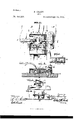
- Figure l of the drawings represents a front elevation of my improved lock, partly in section, to show the interior construction thereof Fig. 2, a longitudinal section taken on line y y of Fig. l; Fig. 3, a detail view on line a a', showing the position of the latch with relation to the keeper.
- Fig. I is a side view of the lock with the case thereof partly broken away, and Fig. 5 a detail view in section taken on line a: of Fig. 1.
- the present invention has for its object to provide a secure lock for refrigerators or other purposes that will be easy of operation as well as simple in its construction, and will securely hold the door of a refrigerator or other like receptacle tightly closed, which objects are attained by the construction, substantially as shown in the drawings, and hereinafter described and claimed.
- A represents a port-ion of a refrigerator or other re-V ceptacle
- B the door, to which my improved lock is applied, the case thereof, as shown at C, being of any suitable construction and provided with any desirable and well-known means for securing it in place upon the door.
- the case C has a base-plate D to foi-1n a complete inclosure for the operating parts of the lock, said plate being connected thereto by a screw a, engaging with a screwhole in a stationary pivot or bearing b, depending from the under side of the case.
- This pivot or bearing b forms a means of pivotally connecting a latch E to the casing, said pivot extending down through an eye c of the latch, as shown more clearly in Fig. 2.
- the latch E has an extension cl to cover the curved slot e in the case C and prevent any dirt or dust working into the case, and the handle F of the latch extends up through this slot, whereby the latch may be operated.
- the latch E extends out through an opening fin the case C and has an inclined bearing g at its end to operate in connection with the inclined bearing-plate h of a keeper G, which is secured by screws or other well-known means to the refrigerator or other like receptacle.
- this bearing-plate the inner one in contradistinction to the second bearing-plate of the keeper, which is shown at ,both of which serve their purpose in'connection with the latch, and which will be hereinafter described.
- a sliding lockingplate H is held within the case CV by means of the guides 7o Z, and the latch E passes through a hole in said plate.
- a bolt l locks the plate Il stationary when in the position shown in Fig.
- the bolt I has a plate m with slots n 0, and said plate rests upon a friction-plate p, which is pivotally connected to the base-plate D by means of the pivot o", which extends up through the slot fn. and forms an additional means of connecting the plates 'm p together.
- the friction-plate p has a slot u and lug u', and a lug o extends from the under side of the plate m into the slot, the lugs forming stops to limit the movement of the upper plate.
- both plates Connecting with the friction-plate p is a suitable spring L, and both plates are operated by a suitable key, as shown at J, whereby the latch may be locked in engagement with the keeper or released, as desired.
Landscapes
- Refrigerator Housings (AREA)
Description
Patented Apr. 14, 1891.
(Nuo Model.)
P. CRADY.
LOOK.
llul/ Nrfrn STATES 'ATENT Orrrcn.
PETER CRADY, OF BURLINGTON, VERMONT. l
SPECIFICATION forming part 0f Letters Patent NO. 450,220, dated April 14,1891.
Application led January 16, 1891. Serial No. 378,020. (No model.)
To a/ZZ. whom, t may concern:
Be it known that I, PETER CRADY, a citizen of the United States, residihg at Burlington, in the county of Chittenden and State of Ven mont, have invented certain new and useful Improvements in VLocks for Refrigerators; and I do hereby declare that the following is a full, clear, and exact description of the same, reference being had to the annexed drawings, making a part of this specification, and to the letters of reference marked thereon.
Figure l of the drawings representsa front elevation of my improved lock, partly in section, to show the interior construction thereof Fig. 2, a longitudinal section taken on line y y of Fig. l; Fig. 3, a detail view on line a a', showing the position of the latch with relation to the keeper. Fig. I is a side view of the lock with the case thereof partly broken away, and Fig. 5 a detail view in section taken on line a: of Fig. 1.
The present invention has for its object to provide a secure lock for refrigerators or other purposes that will be easy of operation as well as simple in its construction, and will securely hold the door of a refrigerator or other like receptacle tightly closed, which objects are attained by the construction, substantially as shown in the drawings, and hereinafter described and claimed.
In the accompanying drawings, A represents a port-ion of a refrigerator or other re-V ceptacle, and B the door, to which my improved lock is applied, the case thereof, as shown at C, being of any suitable construction and provided with any desirable and well-known means for securing it in place upon the door.
The case C has a base-plate D to foi-1n a complete inclosure for the operating parts of the lock, said plate being connected thereto by a screw a, engaging with a screwhole in a stationary pivot or bearing b, depending from the under side of the case. This pivot or bearing b forms a means of pivotally connecting a latch E to the casing, said pivot extending down through an eye c of the latch, as shown more clearly in Fig. 2.
The latch E has an extension cl to cover the curved slot e in the case C and prevent any dirt or dust working into the case, and the handle F of the latch extends up through this slot, whereby the latch may be operated.
The latch E extends out through an opening fin the case C and has an inclined bearing g at its end to operate in connection with the inclined bearing-plate h of a keeper G, which is secured by screws or other well-known means to the refrigerator or other like receptacle. I shall term this bearing-plate the inner one in contradistinction to the second bearing-plate of the keeper, which is shown at ,both of which serve their purpose in'connection with the latch, and which will be hereinafter described. A sliding lockingplate H is held within the case CV by means of the guides 7o Z, and the latch E passes through a hole in said plate. A bolt l locks the plate Il stationary when in the position shown in Fig. l, the bolt passing under the lower edge of the plate and forminga support therefor, thereby holding the latch E in engagement with the keeper G. The bolt Ihas a plate m with slots n 0, and said plate rests upon a friction-plate p, which is pivotally connected to the base-plate D by means of the pivot o", which extends up through the slot fn. and forms an additional means of connecting the plates 'm p together.
rlhe under-sidel of thecase C has a lug s and pin t to hold the plate min position, the pin extending down in the slot 0 to form a guide therefor.
The friction-plate p has a slot u and lug u', and a lug o extends from the under side of the plate m into the slot, the lugs forming stops to limit the movement of the upper plate.
Connecting with the friction-plate p is a suitable spring L, and both plates are operated by a suitable key, as shown at J, whereby the latch may be locked in engagement with the keeper or released, as desired.
In the position shown in Fig. l the door is securely locked, the latch engaging with the keeper, and to unlock it the key is inserted in the key-hole and turned in the direction of the arrow, Fig. 1, which will raise up the friction-plate to bring the lug of the slot above the lug of the upper plate of the bolt. Now this will allow the plate, with its bolt, to move back out of line with the lower edge of IOO the locking-plate and remove the support therefrom, When by pressing upon the handle of the latch itI will be disengaged With the keeper and admit of the door being opened. By means of the weighted handle of the latch or by any other means found best adapted to the purpose, such as a spring or any equivalent device, the latch is automatically brought to a horizontal position. I have shown the handle of sufficient Weight for this purpose, and the spring above described will bring the friction-plate back to its normalposition when released by the key. When the handle of the latch is pressed up, the latch will be forced down out of engagement with the keeper and carry with it thelocking-plate, through which the latch passes, the Weight of the handle, as previously stated, bringing the latch and plate back to the position shown in Fig. l after the door is opened. lVhen the bolt is drawn, as above described, it is held in this position bythe lug on the plate engaging with the lug on the friction-plate upon the oppoF site side. When the door is swung closed, the
end of the latch will strike the inclined plate upon the outside of the keeper and force it down snfliciently to engage With the keeper, and by pressing down upon the handle of the latch the curved portion or inclined bearing thereof will come in contact with the inclined plate on the interior of the keeper, and by its action will draw the door tightly closed, wh en the bolt may be again forced out by the key to lock the plate through which the latch passes in a stationary position, as shown in Fig. 1.
In describing` my invention there are many features in the details of construction that may be variously modified or changed, as might be found necessary. For instance, the
slotted plate of the bolt and the frictionplate upon which it rests and the spring and also the parts immediately connected there with are not absolutely necessary, as other means of Well-known construction might be substituted, andanybolt,therefore,thatwould serve the purpose of holding the looking-plate of the latch stationary and thereby locking the latch to the keeper may be substituted for the means shown. The case of the lock may be also changed, as circumstance would require, and any Well-known form of case could be used that would serve the purpose intended.
I do not Wish to be understood as limiting myself to the construction shown and described of the several parts of the device, as it is evident that many changes may be made in the several details of construction Without departing from the principle of my invention, and I reserve the right to make any such changes or modifications as would come Within ordinary mechanical skill.
Having now fully described my invention, what I claim as new, and desire to secure by Letters Patent, is
In a lock, -th'e combination, with a keeper having inclined bearings extending in opposite directions, of a pivoted latch operating in connection therewith, a verticallysliding locking-plate, and a bolt for supporting the plate in an elevated position and also for releasing it, substantially as and for the purpose set forth.
In testimony that I claim the above I have Vitnesses:
H. E. VVOODBURY, S. M. ATHERTON.
Publications (1)
| Publication Number | Publication Date |
|---|---|
| US450220A true US450220A (en) | 1891-04-14 |
Family
ID=2519103
Family Applications (1)
| Application Number | Title | Priority Date | Filing Date |
|---|---|---|---|
| US450220D Expired - Lifetime US450220A (en) | Peter crady |
Country Status (1)
| Country | Link |
|---|---|
| US (1) | US450220A (en) |
Cited By (1)
| Publication number | Priority date | Publication date | Assignee | Title |
|---|---|---|---|---|
| US2648967A (en) * | 1949-12-22 | 1953-08-18 | Neil O Holmsten | Locking device for window latches |
-
0
- US US450220D patent/US450220A/en not_active Expired - Lifetime
Cited By (1)
| Publication number | Priority date | Publication date | Assignee | Title |
|---|---|---|---|---|
| US2648967A (en) * | 1949-12-22 | 1953-08-18 | Neil O Holmsten | Locking device for window latches |
Similar Documents
| Publication | Publication Date | Title |
|---|---|---|
| US450220A (en) | Peter crady | |
| US1046336A (en) | Sliding-door lock. | |
| US595505A (en) | Door-fastener | |
| US336374A (en) | Hofeerjof | |
| US320036A (en) | Trunk-lock | |
| US617648A (en) | fergusson | |
| US812229A (en) | Sash-lock. | |
| US326626A (en) | George hatter chubb and harry withers chubb | |
| US427157A (en) | Mortise-lock | |
| US557595A (en) | Gravity-lock | |
| US822000A (en) | Lock. | |
| US770408A (en) | Nelson d | |
| US238113A (en) | Ekins hand | |
| US663791A (en) | Lock. | |
| US39001A (en) | Improvement in | |
| US431752A (en) | Latch | |
| US475966A (en) | Fastener for the m eeting-rails of sashes | |
| US432639A (en) | Sash-fastener | |
| US1173112A (en) | Lock. | |
| US526262A (en) | Fastener for meeting-rails of sashes | |
| US147585A (en) | Improvement in padlocks | |
| US2123A (en) | Improvement in door locks and latches | |
| US311898A (en) | Nicholas a | |
| US358976A (en) | Joseph jeczalik | |
| US695888A (en) | Door catch and lock. |