US4500334A - Glass stream cutting apparatus - Google Patents
Glass stream cutting apparatus Download PDFInfo
- Publication number
- US4500334A US4500334A US06/519,446 US51944683A US4500334A US 4500334 A US4500334 A US 4500334A US 51944683 A US51944683 A US 51944683A US 4500334 A US4500334 A US 4500334A
- Authority
- US
- United States
- Prior art keywords
- cam
- carriage
- accordance
- arm
- arms
- Prior art date
- Legal status (The legal status is an assumption and is not a legal conclusion. Google has not performed a legal analysis and makes no representation as to the accuracy of the status listed.)
- Expired - Fee Related
Links
Images


Classifications
-
- C—CHEMISTRY; METALLURGY
- C03—GLASS; MINERAL OR SLAG WOOL
- C03B—MANUFACTURE, SHAPING, OR SUPPLEMENTARY PROCESSES
- C03B7/00—Distributors for the molten glass; Means for taking-off charges of molten glass; Producing the gob, e.g. controlling the gob shape, weight or delivery tact
- C03B7/10—Cutting-off or severing the glass flow with the aid of knives or scissors or non-contacting cutting means, e.g. a gas jet; Construction of the blades used
-
- Y—GENERAL TAGGING OF NEW TECHNOLOGICAL DEVELOPMENTS; GENERAL TAGGING OF CROSS-SECTIONAL TECHNOLOGIES SPANNING OVER SEVERAL SECTIONS OF THE IPC; TECHNICAL SUBJECTS COVERED BY FORMER USPC CROSS-REFERENCE ART COLLECTIONS [XRACs] AND DIGESTS
- Y10—TECHNICAL SUBJECTS COVERED BY FORMER USPC
- Y10T—TECHNICAL SUBJECTS COVERED BY FORMER US CLASSIFICATION
- Y10T83/00—Cutting
- Y10T83/869—Means to drive or to guide tool
- Y10T83/8798—With simple oscillating motion only
- Y10T83/8802—And means to move cooperating cutter member
-
- Y—GENERAL TAGGING OF NEW TECHNOLOGICAL DEVELOPMENTS; GENERAL TAGGING OF CROSS-SECTIONAL TECHNOLOGIES SPANNING OVER SEVERAL SECTIONS OF THE IPC; TECHNICAL SUBJECTS COVERED BY FORMER USPC CROSS-REFERENCE ART COLLECTIONS [XRACs] AND DIGESTS
- Y10—TECHNICAL SUBJECTS COVERED BY FORMER USPC
- Y10T—TECHNICAL SUBJECTS COVERED BY FORMER US CLASSIFICATION
- Y10T83/00—Cutting
- Y10T83/869—Means to drive or to guide tool
- Y10T83/8821—With simple rectilinear reciprocating motion only
Definitions
- Apparatus for cutting a plurality of glass streams into gobs is known to those skilled in the art.
- U.S. Pat. No. 3,592,938 discloses a triple gob stream cutting apparatus.
- the apparatus disclosed in said patent includes a pair of arms reciprocal toward and away from each other and coupled together by a rack and pinions.
- the apparatus in said patent when in the shearing position, orientates the blades so that their cutting edges form the apices of a triangle.
- the apparatus disclosed in said patent is operated by a motor operated cam at a remote location which through rods and lever arms reciprocates the blades toward and away from one another.
- the present invention is directed to apparatus for simultaneously shearing a plurality of glass streams into gobs.
- First and second arms are supported at one end by a discrete carriage for reciprocation in a horizontal direction.
- An electric motor is coupled to the carriages for simultaneously reciprocating the free ends of the arms toward and away from each other.
- Each arm has a plurality of blades adapted to mate with a blade on the other arm.
- the apparatus preferably includes a pneumatic spring for biasing the arms to an open position wherein the arms are remote from each other and for facilitating the locking of the arms in the open position.
- the apparatus preferably includes quadruple sets of blades on the arms and arranged so as to be overlapped with their cutting edges in a row when in the shearing position.
- FIG. 1 is a top plan view of a shear mechanism in accordance with the present invention.
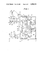
- FIG. 2 is a side elevation view of the shear mechanism shown in FIG. 1 adjustably attached to a spout casing.
- FIG. 3 is a sectional view taken along the line 3--3 in FIG. 2 but on an enlarged scale.
- the shear mechanism includes a frame 12 coupled to the spout casing 14 of a feeder by way of a adjustable mechanism 15 for adjusting the height of the shear mechanism 10 relative to the orifices of the feeder.
- the frame 12 supports a plurality of parallel shafts designated 16, 18 and 20. As shown more clearly in FIG. 2, shafts 16 and 18 are disposed one above the other.
- a carriage 22 is reciprocal along shaft 16 and has an extension 24 which is guided by the shaft 20.
- a second carriage 26 is similarly reciprocal along shaft 18 and has an extension 28 guided by shaft 20.
- each carriage is guided by two different shafts but there are only a total of three shafts whose axes form a triangle.
- a cam follower 30 is attached to the extension 24. See FIG. 1.
- a cam follower 32 is attached to extension 28.
- the carriages 22 and 26 are illustrated in FIG. 1 in a locked-open position.
- the cam followers 30 and 32 are spring biased into contact with the periphery of a cam 34.
- Cam 34 rotates about an axis perpendicular to the axes of shafts 16, 18 and 20.
- Cam 34 is connected to the output from a variable speed gear mechanism 36 to which is connected the output shaft of a high speed electric motor 38 such as a synchronous motor having three horsepower and a speed of 1725 rpm.
- Mechanism 36 and motor 38 are supported by frame portion 39.
- the carriages 22 and 26 reciprocate toward and away from each other due to the contact between cam followers 30, 32 and the cam 34.
- the carriages make two reciprocations per revolution of the cam 34 due to the shape of cam 34.
- Carriage 22 has an arm 40 extending in a direction away from the extension 24.
- Carriage 26 has a similar arm 42.
- Arm 40 has a shank holder 44.
- Arm 42 has a shank holder 46.
- Shanks 48 preferably four in number are, attached to holder 44.
- Shanks 52 preferably four in number, are attached to holder 46.
- a blade 50 is removably attached to each shank 48 and a mating blade 54 is attached to each shank 52.
- the blades 50, 54 are adapted for overlaping contact as illustrated and described in patent 3,592,938. When the blades are in an overlapping shearing position, they are adapted to cut four glass streams aligned in a row as they discharge from the orifice ring of the feeder.
- Shank holder 40 preferably supports a drop guide 56 associated with each blade.
- a mechanical means is provided for adjusting the tension between mating blades at their zone of overlap.
- a bracket 58 is attached to carriage 26 and supports an adjusting mechanism 60.
- Mechanism 60 includes helical gears in a gear box. One of the gears is attached to shaft 68 and the other is attached to shaft 66.
- Shaft 66 is attached to the arm 42 and is adapted to move arm 42 up and down with respect to its carriage 26.
- the shaft 68 supports one of the gears and has an external spur gear 62 cooperating with a latch 64.
- the last mentioned gear and spur gear 62 are mounted on shaft 68 which extends across the frame as shown more clearly in FIG. 1 and terminates at a rachet operated arm 70.
- a pneumatic spring designated generally as 72 is shown more clearly in FIG. 3.
- the pneumatic spring is supported from the frame 12 by bracket 73 and is adapted to maintain the cam followers 30, 32 in contact with the periphery of cam 34 in addition to being able to lock out the arms in their open position as shown in FIGS. 1 and 3.
- the pneumatic spring 72 includes a pneumatic cylinder 74. Within cylinder 74 there is provided a piston 76 connected to one end of piston rod 78. The other end of piston rod 78 is pivotably connected to a bracket 80. Bracket 80 depends from the carriage 26.
- a piston 82 connected to one end of a piston rod 84.
- the other end of rod 84 is pivotably connected to a bracket 86. Bracket 86 depends from the carriage 22.
- a supply and exhaust line 88 is connected to one end of the cylinder 74.
- a supply and exhaust line 90 is connected to the other end of cylinder 74.
- a third supply and exhaust line 92 is connected to a central portion of the cylinder 74.
- cylinder 74 is pressurized by way of line 92 while lines 88 and 90 are exhausted. Vents 94 and 96 for lubricating bushings are provided on opposite ends of the cylinder 74.
- line 92 is exhausted, and cylinder 74 is pressurized by way of lines 88 and 90, the cam followers 30, 32 are biased into contact with the periphery of cam 34. Phantom positions for cam follower 30 are shown in FIG. 3.
- the desired elevation of the shear mechanism 10 is adjusted relative to the spout casing of the feeder by way of mechanism 15.
- Arm 40 is fixed to its carriage 22.
- Arm 42 is vertically adjustable with respect to its carriage 26 so as to attain the proper blade tension by way of mechanism 60.
- the cam followers 30, 32 are in contact with the cam 34.
- Cam 34 is driven by motor 38 through gear box 36. As cam 34 rotates through one revolution, the arms 40, 42 and their associated blades move toward and away from each other twice.
- a gob is sheared from each of the four glass streams discharging from the orifice ring.
- the gobs are conveyed by a distribution device not shown to a I.S. machine which simultaneously converts the four gobs into four glass containers.
Landscapes
- Chemical & Material Sciences (AREA)
- Engineering & Computer Science (AREA)
- Materials Engineering (AREA)
- Organic Chemistry (AREA)
- Re-Forming, After-Treatment, Cutting And Transporting Of Glass Products (AREA)
- Transmission Devices (AREA)
Abstract
Description
Claims (13)
Priority Applications (4)
| Application Number | Priority Date | Filing Date | Title |
|---|---|---|---|
| US06/519,446 US4500334A (en) | 1983-08-02 | 1983-08-02 | Glass stream cutting apparatus |
| GB08419454A GB2144735A (en) | 1983-08-02 | 1984-07-31 | Glass stream cutting apparatus |
| DE3428413A DE3428413C2 (en) | 1983-08-02 | 1984-08-01 | Device for cutting several glass strands simultaneously |
| FR8412263A FR2550183B1 (en) | 1983-08-02 | 1984-08-02 | APPARATUS FOR CUTTING GLASS CASTS |
Applications Claiming Priority (1)
| Application Number | Priority Date | Filing Date | Title |
|---|---|---|---|
| US06/519,446 US4500334A (en) | 1983-08-02 | 1983-08-02 | Glass stream cutting apparatus |
Publications (1)
| Publication Number | Publication Date |
|---|---|
| US4500334A true US4500334A (en) | 1985-02-19 |
Family
ID=24068344
Family Applications (1)
| Application Number | Title | Priority Date | Filing Date |
|---|---|---|---|
| US06/519,446 Expired - Fee Related US4500334A (en) | 1983-08-02 | 1983-08-02 | Glass stream cutting apparatus |
Country Status (4)
| Country | Link |
|---|---|
| US (1) | US4500334A (en) |
| DE (1) | DE3428413C2 (en) |
| FR (1) | FR2550183B1 (en) |
| GB (1) | GB2144735A (en) |
Cited By (4)
| Publication number | Priority date | Publication date | Assignee | Title |
|---|---|---|---|---|
| EP0203740A1 (en) * | 1985-05-07 | 1986-12-03 | Emhart Industries, Inc. | Cam driven straight line shear |
| US4728354A (en) * | 1984-05-14 | 1988-03-01 | Bh-F (Engineering) Limited | Apparatus for straight-line shearing of molten glass gobs |
| US4781746A (en) * | 1987-12-17 | 1988-11-01 | Emhart Industries, Inc. | Drive apparatus for straight line shear mechanism |
| US20240043306A1 (en) * | 2021-05-25 | 2024-02-08 | Nihon Taisanbin Kogyou Kabushiki Kaisha | Molten glass cutting apparatus |
Families Citing this family (1)
| Publication number | Priority date | Publication date | Assignee | Title |
|---|---|---|---|---|
| US4499806A (en) * | 1983-10-13 | 1985-02-19 | Owens-Illinois, Inc. | Multiple gob shearing mechanism operating in a straight line |
Citations (5)
| Publication number | Priority date | Publication date | Assignee | Title |
|---|---|---|---|---|
| US3592938A (en) * | 1968-04-29 | 1971-07-13 | Maul Bros Inc | Glass stream cutting apparatus |
| US3996037A (en) * | 1974-02-08 | 1976-12-07 | Emhart Industries, Inc. | Pass through shears for molten glass feeder |
| US4174647A (en) * | 1978-02-08 | 1979-11-20 | Emhart Industries, Inc. | Apparatus for straight line shearing |
| US4214494A (en) * | 1979-02-21 | 1980-07-29 | Emhart Industries, Inc. | Apparatus for straight line shearing |
| US4214497A (en) * | 1979-02-21 | 1980-07-29 | Emhart Industries, Inc. | Apparatus for straight line shearing |
Family Cites Families (1)
| Publication number | Priority date | Publication date | Assignee | Title |
|---|---|---|---|---|
| US3435719A (en) * | 1967-04-24 | 1969-04-01 | Emhart Corp | Shears for molten glass feeders |
-
1983
- 1983-08-02 US US06/519,446 patent/US4500334A/en not_active Expired - Fee Related
-
1984
- 1984-07-31 GB GB08419454A patent/GB2144735A/en not_active Withdrawn
- 1984-08-01 DE DE3428413A patent/DE3428413C2/en not_active Expired
- 1984-08-02 FR FR8412263A patent/FR2550183B1/en not_active Expired
Patent Citations (5)
| Publication number | Priority date | Publication date | Assignee | Title |
|---|---|---|---|---|
| US3592938A (en) * | 1968-04-29 | 1971-07-13 | Maul Bros Inc | Glass stream cutting apparatus |
| US3996037A (en) * | 1974-02-08 | 1976-12-07 | Emhart Industries, Inc. | Pass through shears for molten glass feeder |
| US4174647A (en) * | 1978-02-08 | 1979-11-20 | Emhart Industries, Inc. | Apparatus for straight line shearing |
| US4214494A (en) * | 1979-02-21 | 1980-07-29 | Emhart Industries, Inc. | Apparatus for straight line shearing |
| US4214497A (en) * | 1979-02-21 | 1980-07-29 | Emhart Industries, Inc. | Apparatus for straight line shearing |
Cited By (5)
| Publication number | Priority date | Publication date | Assignee | Title |
|---|---|---|---|---|
| US4728354A (en) * | 1984-05-14 | 1988-03-01 | Bh-F (Engineering) Limited | Apparatus for straight-line shearing of molten glass gobs |
| EP0203740A1 (en) * | 1985-05-07 | 1986-12-03 | Emhart Industries, Inc. | Cam driven straight line shear |
| US4781746A (en) * | 1987-12-17 | 1988-11-01 | Emhart Industries, Inc. | Drive apparatus for straight line shear mechanism |
| US20240043306A1 (en) * | 2021-05-25 | 2024-02-08 | Nihon Taisanbin Kogyou Kabushiki Kaisha | Molten glass cutting apparatus |
| US11958767B2 (en) * | 2021-05-25 | 2024-04-16 | Nihon Taisanbin Kogyou Kabushiki Kaisha | Molten glass cutting apparatus |
Also Published As
| Publication number | Publication date |
|---|---|
| FR2550183A1 (en) | 1985-02-08 |
| GB2144735A (en) | 1985-03-13 |
| DE3428413C2 (en) | 1987-04-30 |
| DE3428413A1 (en) | 1985-02-21 |
| GB8419454D0 (en) | 1984-09-05 |
| FR2550183B1 (en) | 1987-09-18 |
Similar Documents
| Publication | Publication Date | Title |
|---|---|---|
| US2488046A (en) | Dough extruding and cutting machine | |
| CN205343258U (en) | Slicer for medicinal materials | |
| CN105500420A (en) | Medicinal material cutting machine | |
| US4048891A (en) | Cutter mechanism for cutting sheet material | |
| US4500334A (en) | Glass stream cutting apparatus | |
| US4499806A (en) | Multiple gob shearing mechanism operating in a straight line | |
| KR100188909B1 (en) | A device for gob cutter | |
| US3677732A (en) | Molten glass shears | |
| US4388100A (en) | Shear mechanism for machines for the manufacture of articles of glass or other materials | |
| US3592938A (en) | Glass stream cutting apparatus | |
| US4462290A (en) | Tube cut-off machine | |
| US4939967A (en) | Cut-off machine | |
| GB2049550A (en) | Slicing machine for simultaneously slicing a number of food products | |
| US3916745A (en) | Cutting arrangement | |
| EP0719240B1 (en) | Device for severing gobs from strands of molten glass | |
| US5246478A (en) | Apparatus for cutting molten glass for forming glass products | |
| US4013439A (en) | Gob forming apparatus | |
| US2544527A (en) | Machinery for cutting out pieces of plastic material from a continuously moving sheet | |
| US3786707A (en) | Apparatus for cutting off successive portions from a strand of plastic material such as a strand of viscous glass | |
| US3205746A (en) | Glass shears | |
| US970370A (en) | Wire-cut soft-cake machine. | |
| US2591256A (en) | Biscuit cutting machine and the like | |
| US3818795A (en) | Gear tooth chamfering | |
| US3827323A (en) | Overhung shear | |
| US2036001A (en) | Slicing machine |
Legal Events
| Date | Code | Title | Description |
|---|---|---|---|
| AS | Assignment |
Owner name: MAUL TECHNOLOGY CORPORATION, 111 S. 15TH ST., MILL Free format text: ASSIGNMENT OF ASSIGNORS INTEREST.;ASSIGNORS:PARKELL, EDWARD;NEWKIRK, MARK C.;REEL/FRAME:004215/0101 Effective date: 19830725 |
|
| AS | Assignment |
Owner name: CITICORP INDUSTRIAL CREDIT, INC., BOND COURT BUILD Free format text: SECURITY INTEREST;ASSIGNOR:LGM CORPORATION, A CORP OF IN.;REEL/FRAME:004514/0436 Effective date: 19860212 Owner name: LGM CORPORATION, 9000 PRECISION DRIVE, INDIANAPOLI Free format text: ASSIGNMENT OF ASSIGNORS INTEREST.;ASSIGNOR:IGW SYSTEMS INC.;REEL/FRAME:004828/0916 Effective date: 19860212 Owner name: LGM CORPORATION, 9000 PRECISION DRIVE, INDIANAPOLI Free format text: ASSIGNMENT OF ASSIGNORS INTEREST.;ASSIGNORS:NEWKIRK, MARK C.;IGW SYSTEMS INC.;REEL/FRAME:004828/0927;SIGNING DATES FROM 19860206 TO 19860212 Owner name: LGM CORPORATION, AN IN COMPANY,INDIANA Free format text: ASSIGNMENT OF ASSIGNORS INTEREST;ASSIGNOR:IGW SYSTEMS INC.;REEL/FRAME:004828/0916 Effective date: 19860212 Owner name: LGM CORPORATION, A COMPANY OF INDIANA,INDIANA Free format text: ASSIGNMENT OF ASSIGNORS INTEREST;ASSIGNORS:NEWKIRK, MARK C.;IGW SYSTEMS INC.;SIGNING DATES FROM 19860206 TO 19860212;REEL/FRAME:004828/0927 |
|
| AS | Assignment |
Owner name: MAUL TECHNOLOGY CO., A COMPANY OF DELAWARE Free format text: ASSIGNMENT OF ASSIGNORS INTEREST.;ASSIGNOR:L G M CORPORATION, A CORP OF IND.;REEL/FRAME:004518/0001 Effective date: 19860221 |
|
| AS | Assignment |
Owner name: CITICORP INDUSTRIAL CREDIT, INC., BOND COURT BUILD Free format text: SECURITY INTEREST;ASSIGNOR:MAUL TECHNOLOGY, INC., A CORP OF DE.;REEL/FRAME:004518/0169 Effective date: 19860221 |
|
| FEPP | Fee payment procedure |
Free format text: PAYOR NUMBER ASSIGNED (ORIGINAL EVENT CODE: ASPN); ENTITY STATUS OF PATENT OWNER: LARGE ENTITY |
|
| AS | Assignment |
Owner name: MAUL TECHNOLOGY CO., Free format text: RELEASED BY SECURED PARTY;ASSIGNOR:CITICORP NORTH AMERICA, INC.;REEL/FRAME:004919/0237 Effective date: 19880624 |
|
| REMI | Maintenance fee reminder mailed | ||
| LAPS | Lapse for failure to pay maintenance fees | ||
| STCH | Information on status: patent discontinuation |
Free format text: PATENT EXPIRED DUE TO NONPAYMENT OF MAINTENANCE FEES UNDER 37 CFR 1.362 |
|
| FP | Lapsed due to failure to pay maintenance fee |
Effective date: 19890219 |
|
| AS | Assignment |
Owner name: VHC, LTD., FLORIDA Free format text: ASSIGNMENT OF ASSIGNORS INTEREST.;ASSIGNOR:MAUL TECHNOLOGY COMPANY;REEL/FRAME:005463/0382 Effective date: 19901001 |
|
| AS | Assignment |
Owner name: VHC, LTD., PHILLIPS POINT, EAST TOWER, STE. 700, 7 Free format text: TO CORRECT THE HABITAT OF THE ASSIGNOR IN A DOCUMENT RECORDED AT REEL 5463 FRAMES 382-391. ASSIGNOR HEREBY ASSIGNS NUMC PRO TUNC EFFECTIVE OCTOBER 01, 1990 THE ENTIRE INTEREST TO SAID ASSIGNEE;ASSIGNOR:MAUL TECHNOLOGY COMPANY;REEL/FRAME:005529/0010 Effective date: 19901215 |