US4496085A - Dispensing pump for containers with large closures - Google Patents
Dispensing pump for containers with large closures Download PDFInfo
- Publication number
- US4496085A US4496085A US06/400,701 US40070182A US4496085A US 4496085 A US4496085 A US 4496085A US 40070182 A US40070182 A US 40070182A US 4496085 A US4496085 A US 4496085A
- Authority
- US
- United States
- Prior art keywords
- closure
- plunger
- pump
- container
- top wall
- Prior art date
- Legal status (The legal status is an assumption and is not a legal conclusion. Google has not performed a legal analysis and makes no representation as to the accuracy of the status listed.)
- Expired - Fee Related
Links
Images

Classifications
-
- B—PERFORMING OPERATIONS; TRANSPORTING
- B05—SPRAYING OR ATOMISING IN GENERAL; APPLYING FLUENT MATERIALS TO SURFACES, IN GENERAL
- B05B—SPRAYING APPARATUS; ATOMISING APPARATUS; NOZZLES
- B05B11/00—Single-unit hand-held apparatus in which flow of contents is produced by the muscular force of the operator at the moment of use
- B05B11/01—Single-unit hand-held apparatus in which flow of contents is produced by the muscular force of the operator at the moment of use characterised by the means producing the flow
- B05B11/10—Pump arrangements for transferring the contents from the container to a pump chamber by a sucking effect and forcing the contents out through the dispensing nozzle
- B05B11/1042—Components or details
- B05B11/1059—Means for locking a pump or its actuation means in a fixed position
- B05B11/106—Means for locking a pump or its actuation means in a fixed position in a retracted position, e.g. in an end-of-dispensing-stroke position
-
- B—PERFORMING OPERATIONS; TRANSPORTING
- B05—SPRAYING OR ATOMISING IN GENERAL; APPLYING FLUENT MATERIALS TO SURFACES, IN GENERAL
- B05B—SPRAYING APPARATUS; ATOMISING APPARATUS; NOZZLES
- B05B11/00—Single-unit hand-held apparatus in which flow of contents is produced by the muscular force of the operator at the moment of use
- B05B11/01—Single-unit hand-held apparatus in which flow of contents is produced by the muscular force of the operator at the moment of use characterised by the means producing the flow
- B05B11/10—Pump arrangements for transferring the contents from the container to a pump chamber by a sucking effect and forcing the contents out through the dispensing nozzle
- B05B11/1042—Components or details
- B05B11/1043—Sealing or attachment arrangements between pump and container
- B05B11/1046—Sealing or attachment arrangements between pump and container the pump chamber being arranged substantially coaxially to the neck of the container
- B05B11/1047—Sealing or attachment arrangements between pump and container the pump chamber being arranged substantially coaxially to the neck of the container the pump being preassembled as an independent unit before being mounted on the container
Definitions
- This invention relates to hand-operated dispensing pumps of the type which are selectively lockable with their plungers in a fully depressed position and, more particularly, to an improvement which prevents relative rotation between the pump body and the closure with which it is associated during rotational locking and unlocking of the pump plunger.
- Lock-down dispensing pumps typically rely upon the ability of the plunger to be rotated to a certain degree relative to locking structure on the pump body in order to engage and disengage the lock. In certain situations, however, it may not be possible to hold the pump body immobile using the common technique of clamping a rigid flange of the body between the closure and the upper edge of a neck on the container. Consequently, an important object of the present invention is to provide a way of rendering the pump body, and thus its associated lock structure, immobile relative to the plunger which does not rely upon that type of clamping action, inasmuch as it may or may not be available in any given situation.
- the present invention contemplates configuring the opening of the closure through which the pump extends in such a manner that it cooperates with correspondingly configured, exterior surfaces on the pump body to effectively interlock the pump body and the closure against relative rotation. This, then, assures that the plunger may be freely rotated to the extent necessary or desired during locking and unlocking without that portion of the lock which is on the pump body rotating with the plunger and thereby defeating the user's efforts to lock or unlock the pump.
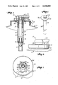
- FIG. 1 is a fragmentary, vertical cross-sectional view of a pump mounted on a container and constructed in accordance with the principles of the present invention
- FIG. 2 is a front perspective view of the lower portion of the pump body illustrating the antirotational surfaces forming a part thereof;
- FIG. 3 is a fragmentary elevational view of the pump and the container of FIG. 1;
- FIG. 4 is a fragmentary, enlarged cross-sectional view of a pump and container illustrating the way in which prior art pumps may be held against rotation by clamping a flange on the pump body between the closure and the upper edge extremity of the neck on the container;
- FIG. 5 is a fragmentary view of the container and pump with the container and certain portions of the pump shown in cross-section while other portions of the pump are shown in elevation to reveal details of construction;
- FIG. 6 is a transverse cross-sectional view of the pump and associated closure of the container taken substantially along line 6--6 of FIG. 5;
- FIG. 7 is a transverse cross-sectional view through the pump taken substantially along line 7--7 of FIG. 5 with portions of the pump, closure and container broken away to reveal details of construction;
- FIG. 8 is an enlarged, transverse cross-sectional view through the lock of the pump illustrating the same in an unlocked mode but with the components thereof aligned just prior to locking;
- FIG. 9 is a transverse cross-sectional view corresponding to FIG. 8 but with the lock components in a locked mode.
- the pump 10 is illustrated in association with a container 12 having a wide neck 14 defining an outlet 16.
- a closure 18 threaded down onto the neck 14 has a top wall 20 provided with a centrally disposed opening 22 through which the pump 10 is inserted.
- the pump 10 includes a tubular body 24 broadly comprising a lower portion 26 situated below the top wall 20 and extending down into the container 12 and an upper collar portion 28 situated primarily above the top wall 20.
- the upper portion 28 has a depending, tubular shank section 30 that is telescopically received within the lower portion 26 during initial installation of the pump 10 on the closure 18 so that a lower edge extremity 28a on upper portion 28 and a circular flange 26a on the lower portion 26 may serve as opposed clamping surfaces to grip the top wall 20 therebetween.
- Tightly interengaging beads and grooves 32 on the tubular section of upper portion 28 and lower portion 26 serve to hold the top wall 20 securely clamped between portions 26 and 28.
- the pump 10 further includes a plunger 34 confined for axial reciprocation within the tubular body 24 between extended and depressed positions.
- a piston 36 of the plunger 34 operates to successively draw liquid up into the chamber 38 of body 24 as the plunger 34 is extended and to then force such accumulation of liquid up through an internal passage of the plunger 34 (not shown) and out a discharge spout 40 thereof when the plunger 34 is thereafter depressed.
- a ball check valve 42 at the lower end of the chamber 38 opens and closes an inlet 44 to the latter in a manner well understood in the art, and a coil spring 46 between the piston 36 and the lower end of the chamber 38 yieldably biases the plunger 34 toward its fully extended position.
- Lock 48 is operable to releasably retain the plunger 34 in a fully depressed condition as illustrated in FIG. 1 and FIG. 3 and includes three radially outwardly projecting, circumferentially spaced-apart ears 50 on the plunger 34 and three upwardly facing, complementally configured notches 52 on the upper body portion 28. When ears 50 are aligned with the notches 52, the plunger 34 may be depressed and then rotated to bring the ears 50 underneath overhanging ledges 54 interspersed between the notches 52 whereby to hold the plunger 34 against extension.
- the closure 18 and the body 24 are provided with interengaging structure broadly denoted by the numeral 56 locking the same against relative rotation.
- the structure 56 on body 24 includes a boss having a circumferentially extending series of flat surfaces 58 on the lower body portion 26 immediately above the flange 26a.
- such surfaces 58 which each extend at a non-uniform distance from the central longitudinal axis of the pump 10 about which the plunger 34 may be rotated, describe an octagonal pattern, although it will be appreciated that other arrangements of surfaces at non-uniform distances from the axis of rotation of the plunger 34 may be provided within the scope of the present invention.
- the structure 56 on closure 18 includes a series of mating edges 60 on the top wall describing and defining the limits of the opening 22, such edges 60 being complementally configured with respect to the surfaces 58 on pump body 24. As illustrated perhaps most clearly in FIG. 5, the flat surfaces 58 are so located on the pump body 24 that they are received within the opening 22 to thereby be in vertical alignment with the edges 60 thereof.
- FIG. 4 For purposes of illustration, a prior art arrangement has been shown in FIG. 4 wherein it will be noted that the flange 126a of the pump body 124 is clamped between the top wall 120 of closure 118 and the upper edge 114a of the container neck 114. Thus, the pump body 124 is securely held against rotation relative to the closure 120.
- the diameter or size of the container neck need be of no concern. Because of the locking-interengagement between the flat surfaces 58 on pump body 24 and the flat edges 60 on closure top wall 20, the pump body 24 is simply not permitted to rotate with the plunger 34 during locking or unlocking rotation thereof. Consequently, the pump 24 may be of standard size for all containers, regardless of the dimension of the necks on such containers.
Abstract
Description
Claims (2)
Priority Applications (1)
| Application Number | Priority Date | Filing Date | Title |
|---|---|---|---|
| US06/400,701 US4496085A (en) | 1982-07-22 | 1982-07-22 | Dispensing pump for containers with large closures |
Applications Claiming Priority (1)
| Application Number | Priority Date | Filing Date | Title |
|---|---|---|---|
| US06/400,701 US4496085A (en) | 1982-07-22 | 1982-07-22 | Dispensing pump for containers with large closures |
Publications (1)
| Publication Number | Publication Date |
|---|---|
| US4496085A true US4496085A (en) | 1985-01-29 |
Family
ID=23584659
Family Applications (1)
| Application Number | Title | Priority Date | Filing Date |
|---|---|---|---|
| US06/400,701 Expired - Fee Related US4496085A (en) | 1982-07-22 | 1982-07-22 | Dispensing pump for containers with large closures |
Country Status (1)
| Country | Link |
|---|---|
| US (1) | US4496085A (en) |
Cited By (11)
| Publication number | Priority date | Publication date | Assignee | Title |
|---|---|---|---|---|
| WO1993003857A2 (en) * | 1991-08-16 | 1993-03-04 | The English Glass Company Limited | Dispenser pumps |
| US5271530A (en) * | 1990-11-07 | 1993-12-21 | Daiwa Can Company | Foam dispensing pump container |
| US5405057A (en) * | 1993-10-21 | 1995-04-11 | Moore; David G. | Manually actuated pump |
| US5570819A (en) * | 1992-07-07 | 1996-11-05 | Daiwa Can Company | Foam dispensing pump container |
| US5725128A (en) * | 1996-03-08 | 1998-03-10 | Contico International, Inc. | Manually operated reciprocating liquid pump that locks and seals in up and down positions |
| US5839616A (en) * | 1997-08-14 | 1998-11-24 | The Procter & Gamble Company | Blow molded container having pivotal connector for an actuation lever |
| US6129322A (en) * | 1998-03-03 | 2000-10-10 | Merkl; Tim W. | Hand pump support |
| US6601735B2 (en) | 2001-01-19 | 2003-08-05 | Valois S.A. | Fluid dispenser device |
| US6695171B2 (en) | 2002-02-12 | 2004-02-24 | Seaquistperfect Dispensing Foreign, Inc. | Pump dispenser |
| US20060113329A1 (en) * | 2004-11-29 | 2006-06-01 | Seaquisperfect Dispensing Foreign, Inc. | Dispenser with lock |
| US7249692B2 (en) | 2004-11-29 | 2007-07-31 | Seaquistperfect Dispensing Foreign, Inc. | Dispenser with lock |
Citations (9)
| Publication number | Priority date | Publication date | Assignee | Title |
|---|---|---|---|---|
| US989435A (en) * | 1910-09-24 | 1911-04-11 | James T Smallwood | Oil-can. |
| US2846124A (en) * | 1956-10-08 | 1958-08-05 | Drackett Co | Dispensing pump unit |
| US2870943A (en) * | 1957-03-04 | 1959-01-27 | Cook Chemical Company | Pump-type liquid sprayer having hold-down cap |
| US3062416A (en) * | 1958-12-01 | 1962-11-06 | Drackett Co | Liquid dispenser |
| US3179306A (en) * | 1963-03-21 | 1965-04-20 | Calmar Inc | Liquid dispenser |
| US3257961A (en) * | 1964-04-23 | 1966-06-28 | Holmes T J Co | Pump |
| US4311256A (en) * | 1980-06-02 | 1982-01-19 | Diamond International Corporation | Mechanical breakup actuator |
| US4340158A (en) * | 1980-06-13 | 1982-07-20 | Realex Corporation | Vent-sealing, down-locked pump dispenser |
| US4371099A (en) * | 1980-11-18 | 1983-02-01 | Realex Corporation | Size-compensating collar in a pump dispenser |
-
1982
- 1982-07-22 US US06/400,701 patent/US4496085A/en not_active Expired - Fee Related
Patent Citations (9)
| Publication number | Priority date | Publication date | Assignee | Title |
|---|---|---|---|---|
| US989435A (en) * | 1910-09-24 | 1911-04-11 | James T Smallwood | Oil-can. |
| US2846124A (en) * | 1956-10-08 | 1958-08-05 | Drackett Co | Dispensing pump unit |
| US2870943A (en) * | 1957-03-04 | 1959-01-27 | Cook Chemical Company | Pump-type liquid sprayer having hold-down cap |
| US3062416A (en) * | 1958-12-01 | 1962-11-06 | Drackett Co | Liquid dispenser |
| US3179306A (en) * | 1963-03-21 | 1965-04-20 | Calmar Inc | Liquid dispenser |
| US3257961A (en) * | 1964-04-23 | 1966-06-28 | Holmes T J Co | Pump |
| US4311256A (en) * | 1980-06-02 | 1982-01-19 | Diamond International Corporation | Mechanical breakup actuator |
| US4340158A (en) * | 1980-06-13 | 1982-07-20 | Realex Corporation | Vent-sealing, down-locked pump dispenser |
| US4371099A (en) * | 1980-11-18 | 1983-02-01 | Realex Corporation | Size-compensating collar in a pump dispenser |
Cited By (14)
| Publication number | Priority date | Publication date | Assignee | Title |
|---|---|---|---|---|
| US5271530A (en) * | 1990-11-07 | 1993-12-21 | Daiwa Can Company | Foam dispensing pump container |
| WO1993003857A3 (en) * | 1991-08-16 | 1993-05-13 | English Glass Co Ltd | Dispenser pumps |
| WO1993003857A2 (en) * | 1991-08-16 | 1993-03-04 | The English Glass Company Limited | Dispenser pumps |
| US5497915A (en) * | 1991-08-16 | 1996-03-12 | The English Glass Company Limited | Dispenser pumps |
| US5570819A (en) * | 1992-07-07 | 1996-11-05 | Daiwa Can Company | Foam dispensing pump container |
| US5405057A (en) * | 1993-10-21 | 1995-04-11 | Moore; David G. | Manually actuated pump |
| EP0737518A1 (en) * | 1993-10-21 | 1996-10-16 | Perfect-Valois Ventil GmbH | Manually actuated pump |
| US5725128A (en) * | 1996-03-08 | 1998-03-10 | Contico International, Inc. | Manually operated reciprocating liquid pump that locks and seals in up and down positions |
| US5839616A (en) * | 1997-08-14 | 1998-11-24 | The Procter & Gamble Company | Blow molded container having pivotal connector for an actuation lever |
| US6129322A (en) * | 1998-03-03 | 2000-10-10 | Merkl; Tim W. | Hand pump support |
| US6601735B2 (en) | 2001-01-19 | 2003-08-05 | Valois S.A. | Fluid dispenser device |
| US6695171B2 (en) | 2002-02-12 | 2004-02-24 | Seaquistperfect Dispensing Foreign, Inc. | Pump dispenser |
| US20060113329A1 (en) * | 2004-11-29 | 2006-06-01 | Seaquisperfect Dispensing Foreign, Inc. | Dispenser with lock |
| US7249692B2 (en) | 2004-11-29 | 2007-07-31 | Seaquistperfect Dispensing Foreign, Inc. | Dispenser with lock |
Similar Documents
| Publication | Publication Date | Title |
|---|---|---|
| US4496085A (en) | Dispensing pump for containers with large closures | |
| US6006949A (en) | Manually operated reciprocating liquid pump with sealing vent opening | |
| US5445299A (en) | Tamper evident lock for liquid pump dispenser | |
| EP0953381B1 (en) | Fluid pump dispenser | |
| US4286736A (en) | Liquid Dispenser | |
| US5238152A (en) | Quick-locking child resistant bottle cap assembly | |
| EP1050478B1 (en) | Bayonet-type finish for a container | |
| US11007546B2 (en) | Child-proof discharger | |
| CA1253829A (en) | Dispensing pump having collar-to-body anti-rotation interlock | |
| EP1658476B1 (en) | Air foam pump with shifting air piston | |
| JPS59166265A (en) | Distributing pump | |
| NZ202430A (en) | Locking ring for plunger of dispensing pump | |
| JP2008536678A (en) | Dispensing device | |
| GB2125906A (en) | Dispensing pump | |
| US4984742A (en) | Container and pump assembly | |
| US5938081A (en) | Container and cap closure | |
| US6896151B1 (en) | Self-closing fluid dispensing closure | |
| US3216624A (en) | Dispenser with stroke restricting overcap | |
| CA2268032C (en) | Fluid pump dispenser | |
| US5025956A (en) | Safety top sprayer | |
| JPH079803Y2 (en) | Improved dispensing device with variable dispensing amount | |
| JP2003292006A (en) | Liquid jetting pump | |
| CN219807170U (en) | Press pump | |
| JPH0420525Y2 (en) | ||
| JP2018188167A (en) | Discharge container |
Legal Events
| Date | Code | Title | Description |
|---|---|---|---|
| AS | Assignment |
Owner name: REALEX CORPORATION; 2500 SUMMIT, KANSAS CITY, MO. Free format text: ASSIGNMENT OF ASSIGNORS INTEREST.;ASSIGNORS:FORD, JOHN M. B.;FOSTER, DONALD D.;REEL/FRAME:004027/0689 Effective date: 19820714 |
|
| FPAY | Fee payment |
Year of fee payment: 4 |
|
| AS | Assignment |
Owner name: CALMAR INC., 40 STIRLING ROAD, WATCHUNG, NJ 07060, Free format text: ASSIGNMENT OF ASSIGNORS INTEREST.;ASSIGNOR:REALEX CORPORATION;REEL/FRAME:004983/0866 Effective date: 19881128 Owner name: CALMAR INC., A CORP. OF DE, NEW JERSEY Free format text: ASSIGNMENT OF ASSIGNORS INTEREST;ASSIGNOR:REALEX CORPORATION;REEL/FRAME:004983/0866 Effective date: 19881128 |
|
| AS | Assignment |
Owner name: CITICORP NORTH AMERICA, INC., AS AGENT, CALIFORNIA Free format text: SECURITY INTEREST;ASSIGNOR:CALMAR INC.;REEL/FRAME:005020/0974 Effective date: 19881208 Owner name: CALMAR INC., A DE CORP., NEW JERSEY Free format text: ASSIGNMENT OF ASSIGNORS INTEREST.;ASSIGNOR:REALEX CORPORATION;REEL/FRAME:005020/0968 Effective date: 19881130 |
|
| FEPP | Fee payment procedure |
Free format text: PAYOR NUMBER ASSIGNED (ORIGINAL EVENT CODE: ASPN); ENTITY STATUS OF PATENT OWNER: LARGE ENTITY |
|
| AS | Assignment |
Owner name: UNITED STATES TRUST COMPANY OF NEW YORK, NEW YORK Free format text: SECURITY INTEREST;ASSIGNOR:CALMAR INC.;REEL/FRAME:006608/0452 Effective date: 19911223 |
|
| AS | Assignment |
Owner name: CALMAR INC., A CORPORATION OF DELAWARE, CALIFORNIA Free format text: RELEASE BY SECURED PARTY OF A SECURITY AGREEMENT RECORDED AT REEL 5020 FRAME 0974 AND DATED 12-08-88;ASSIGNOR:CITICORP NORTH AMERICA, INC.;REEL/FRAME:006082/0535 Effective date: 19911212 |
|
| REMI | Maintenance fee reminder mailed | ||
| LAPS | Lapse for failure to pay maintenance fees | ||
| FP | Lapsed due to failure to pay maintenance fee |
Effective date: 19930131 |
|
| AS | Assignment |
Owner name: MELLON BANK, N.A., AS COLLATERAL AGENT, PENNSYLVAN Free format text: PATENT COLLATERAL SECURITY AGREEMENT;ASSIGNOR:CALMAR INC., A DELAWARE CORPORATION;REEL/FRAME:007662/0551 Effective date: 19950918 Owner name: CALMAR INC., A DE CORP., CALIFORNIA Free format text: TERMINATION AND RELEASE OF INTELLECTUAL PROPERTY PLEDGE AGREEMENT;ASSIGNOR:UNITED STATES TRUST COMPANY OF NEW YORK, AS COLLATERAL AGENT;REEL/FRAME:007648/0338 Effective date: 19950918 |
|
| AS | Assignment |
Owner name: BANQUE INDOSUEZ, AS COLLATERAL AGENT, NEW YORK Free format text: SECURITY INTEREST;ASSIGNOR:MELLON BANK, N.A., AS COLLATERAL AGENT;REEL/FRAME:008186/0912 Effective date: 19961025 |
|
| AS | Assignment |
Owner name: CALMAR, INC., CALIFORNIA Free format text: TERMINATION OF PATENT SECURITY INTERESTS;ASSIGNOR:BANQUE INDOSUEZ, AS COLLATERAL AGENT;REEL/FRAME:009375/0018 Effective date: 19980722 |
|
| STCH | Information on status: patent discontinuation |
Free format text: PATENT EXPIRED DUE TO NONPAYMENT OF MAINTENANCE FEES UNDER 37 CFR 1.362 |