US4492291A - Device for damping shocks caused by _moving heavy objects - Google Patents
Device for damping shocks caused by _moving heavy objects Download PDFInfo
- Publication number
- US4492291A US4492291A US06/347,378 US34737882A US4492291A US 4492291 A US4492291 A US 4492291A US 34737882 A US34737882 A US 34737882A US 4492291 A US4492291 A US 4492291A
- Authority
- US
- United States
- Prior art keywords
- members
- perforated sheet
- edge portions
- supplementary
- sheet
- Prior art date
- Legal status (The legal status is an assumption and is not a legal conclusion. Google has not performed a legal analysis and makes no representation as to the accuracy of the status listed.)
- Expired - Fee Related
Links
Images
Classifications
-
- F—MECHANICAL ENGINEERING; LIGHTING; HEATING; WEAPONS; BLASTING
- F16—ENGINEERING ELEMENTS AND UNITS; GENERAL MEASURES FOR PRODUCING AND MAINTAINING EFFECTIVE FUNCTIONING OF MACHINES OR INSTALLATIONS; THERMAL INSULATION IN GENERAL
- F16F—SPRINGS; SHOCK-ABSORBERS; MEANS FOR DAMPING VIBRATION
- F16F7/00—Vibration-dampers; Shock-absorbers
- F16F7/12—Vibration-dampers; Shock-absorbers using plastic deformation of members
-
- G—PHYSICS
- G21—NUCLEAR PHYSICS; NUCLEAR ENGINEERING
- G21C—NUCLEAR REACTORS
- G21C19/00—Arrangements for treating, for handling, or for facilitating the handling of, fuel or other materials which are used within the reactor, e.g. within its pressure vessel
- G21C19/02—Details of handling arrangements
- G21C19/06—Magazines for holding fuel elements or control elements
- G21C19/07—Storage racks; Storage pools
-
- Y—GENERAL TAGGING OF NEW TECHNOLOGICAL DEVELOPMENTS; GENERAL TAGGING OF CROSS-SECTIONAL TECHNOLOGIES SPANNING OVER SEVERAL SECTIONS OF THE IPC; TECHNICAL SUBJECTS COVERED BY FORMER USPC CROSS-REFERENCE ART COLLECTIONS [XRACs] AND DIGESTS
- Y02—TECHNOLOGIES OR APPLICATIONS FOR MITIGATION OR ADAPTATION AGAINST CLIMATE CHANGE
- Y02E—REDUCTION OF GREENHOUSE GAS [GHG] EMISSIONS, RELATED TO ENERGY GENERATION, TRANSMISSION OR DISTRIBUTION
- Y02E30/00—Energy generation of nuclear origin
- Y02E30/30—Nuclear fission reactors
Definitions
- the present invention relates to a device for damping the shocks caused by heavy objects and particularly as a result of the accidental dropping of transported packages into ponds for the discharge of radioactive products.
- These packages which are also called coffins or flasks, will be termed caskets throughout the remainder of the description.
- a break or fracture to the system would lead to the casket dropping and during its impact with the pond wall would on the one hand make a hole in the wall and on the other, if the casket was very heavy, could break through the concrete floor on which the wall is located and cause unacceptable damage to adjacent structures.
- Another known solution consists of placing on the bottom of the pond tight metal shock absorbers having a honeycomb structure and whose cavities are filled with air. These cushioning layers are effective, but onerous. It may also be necessary to ballast or fix the cushioning layers to the bottom of the pond and insure their sealing. The reason is that, when filled with water, said layers are ineffective. Furthermore, such cushioning layers are only effective if they receive a vertical impact force and not an oblique impact force.
- the present invention relates to a device obviating the aforementioned disadvantages and which is also effective in the case of oblique impacts or shocks.
- the device comprises at least one group of deformable mechanical members having a first end connected to a first plate and a second end connected to a second plate, the mechanical members being arranged perpendicularly to said plates, wherein a supplementary plate, whose weight is substantially the same as that of each mechanical member, is positioned between the latter and the second plate, the supplementary plates being contiguous and each mechanical member has at least one predeformation in the vicinity of its second end connected to the second plate.
- the predeformations are made so that they may avoid a pressure peak at the time of impact.
- the dimensions of the tubes are calculated so that, when used in a liquid, the part of overpressure transmitted by the liquid is negligible.
- the second plate comprises a perforated sheet fixed to the supplementary plates and an unperforated sheet fixed by its edges to the face of the perforated sheet opposite to the supplementary plates.
- the perforated sheet provides a connection between the supplementary plates in such a way that they remain in contact with one another and maintain the spacing between the mechanical members at the time of impact, no matter what is the direction of the impact.
- the unperforated sheet has a protective function with respect to the perforated sheet, being able to slide with respect to the latter and prevent puncturing thereof.
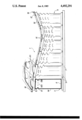
- the device 1 comprises a group of vertically arranged tubes 4, whose bottom 5 and top 6 are respectively connected with a first or lower plate 7 and a second or upper plate 18.
- Each of the tubes 4 is filled with air and is sealed at its bottom by a welded metal plug 9 to which is welded a lower square plate 11, and it is similarly sealed at its top by a welded plug 10 to which is welded an upper square plate 12.
- the respective square plates 9 and 10 are themselves fixed by welding to plate 7 and plate 18.
- Plates 12 or supplementary plates have sides whose length exceeds the diameter of the tubes and which are contiguous.
- the side wall 14 of each tube has one or more predeformations 15 obtained by squeezing or nipping in an area adjacent to the top. These predeformations ensure that the tube is deformed by crushing from the top in accordance with its own vibration mode under the action of an impact. As in the present case the tube deforms in three directions, it is important to have three predeformations 15, 15A and 15B, located in the same horizontal plane and displaced from one another.
- the upper plate 18 which, according to the invention, comprises an upper unperforated sheet 16 joined by its edges to a perforated sheet 17, e.g. by welding.
- Sheet 17 has perforations 20 in the form of circular holes with a diameter substantially equal to that of tubes 4 and positioned roughly concentrically to the latter. Perforated sheet 17 is welded to the supplementary plates 12 at the edges of perforations 20.
- the device has received an impact at a point in the right hand portion of the drawing.
- the two sheets 16 and 17 have deformed, whilst crushing to a greater or lesser extent the tubes positioned below them.
- the thickness of the unperforated sheet 16 is such that it protects the perforated sheet 17 at the time of impact by being able to slide with respect to the latter and prevent the puncturing of the perforated sheet under the effect of the impact.
- the perforated sheet 17 remains joined to the supplementary plates 12, because it is the unperforated sheet which slides with respect to the remainder of the device.
- the thickness of the perforated sheet is such that it continues to provide a connection between the plates 12 after the impact, in order that the latter remain in contact with one another, no matter what the direction of the impact relative to the axis of the tubes.
- each tube can deform without there being any risk of it coming into contact with adjacent tubes, which makes it possible to absorb a maximum amount of energy by crushing.
- the supplementary plates 12 are perfectly continguous. It is merely necessary for them to so come together during movement as to ensure that the tubes do not come into contact with one another.
- Such a disposal also permits the energy of impact to be distributed over a large number of tubes.
- the predeformations such as 15, 15A and 15B are indispensable for ensuring that the tube is crushed or flattened for absorbing the impact energy.
- the size of the predeformations must be large enough to avoid a pressure peak, but not too large however because a too large deformation could affect the stability of the tubes under static load.
- the dimensions of the shock absorber have been calculated so as to be able to solve the following problem. It is desired to damp a drop of 2.2 m in air and of 10 m in water of a 116 ton casket with a damping travel of 1 m (i.e. a reduction in the shock absorber height by corrugating or folding the sidewall of the tubes by 1 m).
- the impact conditions of the casket are such that the angle of the velocity vector with the vertical of the centre of gravity of the casket can reach 10° and the position of the bottom of the casket is such that it is in contact with the shock absorber along an edge.
- the lower face can be inclined by 45° relative to the horizontal in the least favourable case.
- the instantaneous maximum load does not exceed one of the following values in any random area:
- the shock absorbers must be able to withstand without deformation a casket approach speed of 0.5 m/mn.
- the result of the hydrostatic lifts exerted on the device is such that the latter is immobilized at the bottom of the pool as a result of its own weight, so that there is no need to provide a fastening on the pool bottom or any separate ballasting.
- a shock absorber formed from tubes having an outside diameter of 408 mm, a predeformed sidewall of thickness 4 mm, each tube being sealed by two 15 mm thick metal plugs to which are welded a 15 mm lower plate and a 30 mm thick supplementary plate.
- the supplementary plates are welded to a continuous 16 mm thick upper plate and the tubes are uniformal distributed in accordance with a density of 4 tubes/m 2 .
- the height of the tubes is 1515 mm.
- the metal used is stainless steel Z2CN 15 10 (304 L).
- a clamp In order to predeform the tubes they are introduced horizontally into a clamp, whose lower fixed jaw has a V-shape and a rounded top formed by two blades cutting at an angle of 60° and whose upper movable jaw is a straight cutting blade, the thickness of the cutting edge of the three blades being 30 mm.
- a suitable load is applied to the movable jaw for obtaining on the lateral surface of the tube, approximately 20 cm from the top, a triangular predeformed area positioned approximately 20 cm from the top and whose maximum deflection is approximately 40 mm.
- the device according to the invention offers interesting advantages, particularly with regards to its strength in the case of an oblique impact.
- the thicknesses of the perforated and unperforated sheets forming the upper plate 18 are such that, even in the case of an oblique shock, the perforated sheet deforms whilst remaining connected to the supplementary plates 12, which remain substantially contiguous and enable the tubes to freely deform along their vertical axis.
- the device absorbs a large part of the energy due to the impact and prevents a certain number of disadvantages occurring in the prior art, e.g. bouncing or rebound of the casket.
- hollow cylinders can be replaced by hollow truncated cones or it is also possible to use several groups of mechanical members according to the invention arranged in superimposed manner, the groups being linked by means of intermediate plates.
- the tubes When used in water the tubes must be liquid-tight.
- the device such as above-described leads to a good sealing, but it may be advantageous to fill them with a liquid-tight crushable material, preferably a light-weight material such as expanded polystryrene.
- a liquid-tight crushable material preferably a light-weight material such as expanded polystryrene.
- the tubes filled with this material remain effective, even if their wall is no longer liquid-tight.
- a shock absorbing device can be constructed in such a way that it is fixed to a movable or stationary structure or it is possible to provide a movable device (e.g. simply placed on the bottom of a pond), which can be moved from one installation to another. It is also possible to produce such a device in the form of a single block of relatively large size or to juxtapose a pluraity of smaller shock absorbers.
- the device is positioned vertically in order to protect the bottom of a pond, it is possible to envisage applications in which the first and second plates surrounding the deformable members have a random orientation, the second plate and supplementary plates still being positioned on the side exposed to the impacts or shocks.
- the device according to the invention can be used in all cases where there is a risk of heavy objects dropping or causing a shock either in a liquid medium or in air.
Landscapes
- Engineering & Computer Science (AREA)
- General Engineering & Computer Science (AREA)
- Physics & Mathematics (AREA)
- Plasma & Fusion (AREA)
- High Energy & Nuclear Physics (AREA)
- Mechanical Engineering (AREA)
- Vibration Dampers (AREA)
- Vibration Prevention Devices (AREA)
Abstract
Description
Claims (4)
Applications Claiming Priority (2)
| Application Number | Priority Date | Filing Date | Title |
|---|---|---|---|
| FR8102882 | 1981-02-13 | ||
| FR8102882A FR2500098B1 (en) | 1981-02-13 | 1981-02-13 | DAMPING DEVICE AGAINST SHOCK CAUSED BY HEAVY OBJECTS |
Publications (1)
| Publication Number | Publication Date |
|---|---|
| US4492291A true US4492291A (en) | 1985-01-08 |
Family
ID=9255184
Family Applications (1)
| Application Number | Title | Priority Date | Filing Date |
|---|---|---|---|
| US06/347,378 Expired - Fee Related US4492291A (en) | 1981-02-13 | 1982-02-10 | Device for damping shocks caused by _moving heavy objects |
Country Status (5)
| Country | Link |
|---|---|
| US (1) | US4492291A (en) |
| EP (1) | EP0058615B1 (en) |
| JP (1) | JPS57149637A (en) |
| DE (1) | DE3265502D1 (en) |
| FR (1) | FR2500098B1 (en) |
Cited By (35)
| Publication number | Priority date | Publication date | Assignee | Title |
|---|---|---|---|---|
| US4830347A (en) * | 1983-05-23 | 1989-05-16 | Marathon Oil Company | Assembly for and a method of absorbing impact shock loads |
| US4849157A (en) * | 1983-12-15 | 1989-07-18 | Interatom Gmbh | Core barrel for a high-temperature nuclear reactor |
| US4915540A (en) * | 1989-06-05 | 1990-04-10 | Jack Kennedy Metal Products And Buildings, Inc. | Contractible mine stopping and contractible block member for use therein |
| USRE34220E (en) * | 1989-06-05 | 1993-04-13 | Jack Kennedy Metal Products And Buildings, Inc. | Contractible mine stopping and contractible block member for use therein |
| US5379711A (en) * | 1992-09-30 | 1995-01-10 | The United States Of America As Represented By The Secretary Of The Navy | Retrofittable monolithic box beam composite hull system |
| DE19526119A1 (en) * | 1995-07-19 | 1997-01-23 | Michael T Dipl Ing Witt | Car bumper with impact energy absorber |
| US5690232A (en) * | 1995-06-06 | 1997-11-25 | Emery; Roy William | Resilient wraparound cushion packing |
| WO2001060675A1 (en) * | 2000-02-18 | 2001-08-23 | Siemens Sgp Verkehrstechnik Gmbh | Crumple element |
| US20020020261A1 (en) * | 2000-08-14 | 2002-02-21 | Gass Stephen F. | Replaceable brake mechanism for power equipment |
| US20030005588A1 (en) * | 2001-07-03 | 2003-01-09 | Gass Stephen F. | Actuators for use in fast-acting safety systems |
| US20030140749A1 (en) * | 2002-01-25 | 2003-07-31 | Gass Stephen F. | Brake Pawls for power equipment |
| US20040003974A1 (en) * | 2000-10-24 | 2004-01-08 | Michael Ashmead | Energy absoring bumper structure |
| US20040041319A1 (en) * | 2002-08-28 | 2004-03-04 | Kojima Press Industry Co., Ltd. | Shock absorbing structure for vehicle |
| US20050023164A1 (en) * | 2003-07-31 | 2005-02-03 | Ta-Kwang Hung | Tool box with plane positioning means |
| US6851892B2 (en) | 2003-02-10 | 2005-02-08 | Saudi Arabian Oil Company | Marine impact-absorbing structure |
| US20050039822A1 (en) * | 2003-08-20 | 2005-02-24 | Gass Stephen F. | Woodworking machines with overmolded arbors |
| US20050066784A1 (en) * | 2000-09-29 | 2005-03-31 | Gass Stephen F. | Safety methods for use in power equipment |
| US20050139056A1 (en) * | 2003-12-31 | 2005-06-30 | Gass Stephen F. | Fences for table saws |
| US20050166736A1 (en) * | 2004-01-29 | 2005-08-04 | Gass Stephen F. | Table saws with safety systems and systems to mount and index attachments |
| US20060180451A1 (en) * | 1999-10-01 | 2006-08-17 | Gass Stephen F | Switch box for power tools with safety systems |
| US20060179983A1 (en) * | 1999-10-01 | 2006-08-17 | Gass Stephen F | Brake mechanism for power equipment |
| US20060230896A1 (en) * | 1999-10-01 | 2006-10-19 | Gass Stephen F | Miter saw with improved safety system |
| US20060237976A1 (en) * | 2005-04-20 | 2006-10-26 | Shape Corporation | Crushable structure manufactured from mechanical expansion |
| US20060272463A1 (en) * | 2000-08-14 | 2006-12-07 | Gass Stephen F | Motion detecting system for use in a safety system for power equipment |
| US20070003373A1 (en) * | 2005-07-01 | 2007-01-04 | Saudi Arabian Oil Company | Cubic marine impact-absorbing structure |
| US20070101842A1 (en) * | 2003-08-20 | 2007-05-10 | Gass Stephen F | Woodworking machines with overmolded arbors |
| US20070131071A1 (en) * | 2001-07-02 | 2007-06-14 | Gass Stephen F | Discrete proximity detection system |
| US7421315B2 (en) | 2001-11-13 | 2008-09-02 | Sd3, Llc | Detection system for power equipment |
| US7827893B2 (en) | 2003-12-31 | 2010-11-09 | Sd3, Llc | Elevation mechanism for table saws |
| US20120118690A1 (en) * | 2009-04-07 | 2012-05-17 | Dallas Rex James | Energy absorption device |
| FR3001514A1 (en) * | 2013-01-31 | 2014-08-01 | Eiffage Construction Metallique | IMPACT ABSORBER DEVICE |
| FR3082555A1 (en) * | 2018-06-18 | 2019-12-20 | Safran Aircraft Engines | RECTIFIER BLADE WHEEL OF AN AIRCRAFT ENGINE, SUCH AS A TURBOJET |
| US10964437B2 (en) * | 2013-12-31 | 2021-03-30 | Nuscale Power, Llc | Managing dynamic forces on a nuclear reactor system |
| US11298913B2 (en) * | 2015-06-02 | 2022-04-12 | Wavecel, Llc | Energy-absorbing structure with defined multi-phasic crush properties |
| US20230094189A1 (en) * | 2021-09-28 | 2023-03-30 | Sam Austin | Method and apparatus for reducing dynamic forces on doors and windows and barriers and their supports |
Families Citing this family (9)
| Publication number | Priority date | Publication date | Assignee | Title |
|---|---|---|---|---|
| FR2500098B1 (en) * | 1981-02-13 | 1985-12-06 | Commissariat Energie Atomique | DAMPING DEVICE AGAINST SHOCK CAUSED BY HEAVY OBJECTS |
| RU2104423C1 (en) * | 1995-07-03 | 1998-02-10 | Вадим Алексеевич Никитин | Inertial antishock damper |
| FR2747445A1 (en) * | 1996-04-16 | 1997-10-17 | Cera | SHOCK ABSORBING DEVICE |
| RU2200989C2 (en) * | 2001-05-14 | 2003-03-20 | Открытое акционерное общество "ЭМК-Атоммаш" | Damping device |
| EP2256749A1 (en) * | 2009-05-27 | 2010-12-01 | Evonik Energy Services GmbH | Impact dampening device for transport/storage containers for radioactive material |
| JP5951359B2 (en) * | 2012-05-28 | 2016-07-13 | 三菱重工業株式会社 | Fuel storage facility |
| JP6372048B2 (en) * | 2013-03-19 | 2018-08-15 | 日産自動車株式会社 | Shock absorber |
| JP6165028B2 (en) * | 2013-10-31 | 2017-07-19 | 三菱重工業株式会社 | Radioactive substance storage container support stand |
| JP2018084487A (en) * | 2016-11-24 | 2018-05-31 | 日立Geニュークリア・エナジー株式会社 | Nuclear equipment |
Citations (22)
| Publication number | Priority date | Publication date | Assignee | Title |
|---|---|---|---|---|
| US194580A (en) * | 1877-08-28 | Improvement in spring-floors | ||
| GB928111A (en) * | 1959-05-08 | 1963-06-06 | Atomic Energy Authority Uk | Improvements in or relating to energy absorbing devices |
| FR1451407A (en) * | 1965-07-13 | 1966-01-07 | Commissariat Energie Atomique | Safety device for nuclear reactor |
| US3305452A (en) * | 1967-02-21 | Fall-damping device for a nuclear reactor | ||
| US3412628A (en) * | 1966-07-14 | 1968-11-26 | Koppy Tool Corp | Shock absorbing structural member |
| US3446469A (en) * | 1967-11-14 | 1969-05-27 | Us Navy | Scissor shock platform |
| US3760753A (en) * | 1971-04-15 | 1973-09-25 | Nuclear Waste Systems Co | Floatable-submersible vessel container |
| DE2212684A1 (en) * | 1972-03-16 | 1973-09-27 | Gsk Ges Fuer Systemengineering | DEVICE FOR CONVERTING KINETIC ENERGY |
| US3930665A (en) * | 1973-08-24 | 1976-01-06 | Nissan Motor Company Limited | Energy absorbing panel structure |
| US3935467A (en) * | 1973-11-09 | 1976-01-27 | Nuclear Engineering Co., Inc. | Repository for fissile materials |
| DE2613655A1 (en) * | 1976-03-31 | 1977-10-13 | Volkswagenwerk Ag | TORSIONAL, TUBULAR COMPONENT, LONGITUDINAL AND TRANSVERSAL WITH LIGHT LOADS |
| US4104118A (en) * | 1975-11-26 | 1978-08-01 | General Atomic Company | Shock absorber |
| US4137116A (en) * | 1977-04-22 | 1979-01-30 | Miller Brothers | Method of making a pressure switch |
| US4150186A (en) * | 1976-07-21 | 1979-04-17 | Nissan Motor Company, Limited | Composite board structure and a method of and an apparatus for producing the board structure |
| US4190276A (en) * | 1976-12-22 | 1980-02-26 | Mitsubishi Jidosha Kogyo Kabushiki Kaisha | Deformable impact absorbing device for vehicles |
| DE2840559A1 (en) * | 1978-09-18 | 1980-03-27 | Kraftwerk Union Ag | Handling water-cooled reactor fuel elements in two-tier pool - with safety trolley below upper rack units during handling |
| US4227593A (en) * | 1976-10-04 | 1980-10-14 | H. H. Robertson Company | Kinetic energy absorbing pad |
| US4241810A (en) * | 1979-08-29 | 1980-12-30 | The United States Of America As Represented By The United States Department Of Energy | Device for absorbing mechanical shock |
| US4326820A (en) * | 1978-11-28 | 1982-04-27 | Gesellschaft Fur Strahlen-Und Umweltforschung Mbh Munchen | Final depository for radioactive wastes |
| EP0058615A1 (en) * | 1981-02-13 | 1982-08-25 | Commissariat à l'Energie Atomique | Shock absorbing arrangement used against shocks caused by heavy objects |
| US4384020A (en) * | 1980-12-22 | 1983-05-17 | Rohr Industries, Inc. | Honeycomb noise attenuating structures |
| US4428700A (en) * | 1981-08-03 | 1984-01-31 | E. R. Johnson Associates, Inc. | Method for disposing of waste materials |
Family Cites Families (1)
| Publication number | Priority date | Publication date | Assignee | Title |
|---|---|---|---|---|
| FR2840559B1 (en) * | 2002-06-05 | 2005-08-12 | A P S Engineering | THERMAL PRINTING MODULE EQUIPPED WITH SECURITY MEANS AGAINST A DEFECTIVE CONNECTION BETWEEN CONNECTORS EQUIPPED WITH THE MODULE AND THE MACHINE PROVIDED FOR EQUIPPING THEREOF |
-
1981
- 1981-02-13 FR FR8102882A patent/FR2500098B1/en not_active Expired
-
1982
- 1982-02-10 US US06/347,378 patent/US4492291A/en not_active Expired - Fee Related
- 1982-02-11 EP EP82400249A patent/EP0058615B1/en not_active Expired
- 1982-02-11 DE DE8282400249T patent/DE3265502D1/en not_active Expired
- 1982-02-12 JP JP57021930A patent/JPS57149637A/en active Granted
Patent Citations (22)
| Publication number | Priority date | Publication date | Assignee | Title |
|---|---|---|---|---|
| US3305452A (en) * | 1967-02-21 | Fall-damping device for a nuclear reactor | ||
| US194580A (en) * | 1877-08-28 | Improvement in spring-floors | ||
| GB928111A (en) * | 1959-05-08 | 1963-06-06 | Atomic Energy Authority Uk | Improvements in or relating to energy absorbing devices |
| FR1451407A (en) * | 1965-07-13 | 1966-01-07 | Commissariat Energie Atomique | Safety device for nuclear reactor |
| US3412628A (en) * | 1966-07-14 | 1968-11-26 | Koppy Tool Corp | Shock absorbing structural member |
| US3446469A (en) * | 1967-11-14 | 1969-05-27 | Us Navy | Scissor shock platform |
| US3760753A (en) * | 1971-04-15 | 1973-09-25 | Nuclear Waste Systems Co | Floatable-submersible vessel container |
| DE2212684A1 (en) * | 1972-03-16 | 1973-09-27 | Gsk Ges Fuer Systemengineering | DEVICE FOR CONVERTING KINETIC ENERGY |
| US3930665A (en) * | 1973-08-24 | 1976-01-06 | Nissan Motor Company Limited | Energy absorbing panel structure |
| US3935467A (en) * | 1973-11-09 | 1976-01-27 | Nuclear Engineering Co., Inc. | Repository for fissile materials |
| US4104118A (en) * | 1975-11-26 | 1978-08-01 | General Atomic Company | Shock absorber |
| DE2613655A1 (en) * | 1976-03-31 | 1977-10-13 | Volkswagenwerk Ag | TORSIONAL, TUBULAR COMPONENT, LONGITUDINAL AND TRANSVERSAL WITH LIGHT LOADS |
| US4150186A (en) * | 1976-07-21 | 1979-04-17 | Nissan Motor Company, Limited | Composite board structure and a method of and an apparatus for producing the board structure |
| US4227593A (en) * | 1976-10-04 | 1980-10-14 | H. H. Robertson Company | Kinetic energy absorbing pad |
| US4190276A (en) * | 1976-12-22 | 1980-02-26 | Mitsubishi Jidosha Kogyo Kabushiki Kaisha | Deformable impact absorbing device for vehicles |
| US4137116A (en) * | 1977-04-22 | 1979-01-30 | Miller Brothers | Method of making a pressure switch |
| DE2840559A1 (en) * | 1978-09-18 | 1980-03-27 | Kraftwerk Union Ag | Handling water-cooled reactor fuel elements in two-tier pool - with safety trolley below upper rack units during handling |
| US4326820A (en) * | 1978-11-28 | 1982-04-27 | Gesellschaft Fur Strahlen-Und Umweltforschung Mbh Munchen | Final depository for radioactive wastes |
| US4241810A (en) * | 1979-08-29 | 1980-12-30 | The United States Of America As Represented By The United States Department Of Energy | Device for absorbing mechanical shock |
| US4384020A (en) * | 1980-12-22 | 1983-05-17 | Rohr Industries, Inc. | Honeycomb noise attenuating structures |
| EP0058615A1 (en) * | 1981-02-13 | 1982-08-25 | Commissariat à l'Energie Atomique | Shock absorbing arrangement used against shocks caused by heavy objects |
| US4428700A (en) * | 1981-08-03 | 1984-01-31 | E. R. Johnson Associates, Inc. | Method for disposing of waste materials |
Cited By (73)
| Publication number | Priority date | Publication date | Assignee | Title |
|---|---|---|---|---|
| US4830347A (en) * | 1983-05-23 | 1989-05-16 | Marathon Oil Company | Assembly for and a method of absorbing impact shock loads |
| US4849157A (en) * | 1983-12-15 | 1989-07-18 | Interatom Gmbh | Core barrel for a high-temperature nuclear reactor |
| US4915540A (en) * | 1989-06-05 | 1990-04-10 | Jack Kennedy Metal Products And Buildings, Inc. | Contractible mine stopping and contractible block member for use therein |
| USRE34220E (en) * | 1989-06-05 | 1993-04-13 | Jack Kennedy Metal Products And Buildings, Inc. | Contractible mine stopping and contractible block member for use therein |
| US5379711A (en) * | 1992-09-30 | 1995-01-10 | The United States Of America As Represented By The Secretary Of The Navy | Retrofittable monolithic box beam composite hull system |
| US5690232A (en) * | 1995-06-06 | 1997-11-25 | Emery; Roy William | Resilient wraparound cushion packing |
| DE19526119C2 (en) * | 1995-07-19 | 2002-10-24 | Michael T Witt | Impact energy absorbing device |
| DE19526119A1 (en) * | 1995-07-19 | 1997-01-23 | Michael T Dipl Ing Witt | Car bumper with impact energy absorber |
| US20110023673A1 (en) * | 1999-10-01 | 2011-02-03 | Gass Stephen F | Power equipment with detection and reaction systems |
| US8408106B2 (en) | 1999-10-01 | 2013-04-02 | Sd3, Llc | Method of operating power equipment with detection and reaction systems |
| US8196499B2 (en) | 1999-10-01 | 2012-06-12 | Sd3, Llc | Power equipment with detection and reaction systems |
| US10335972B2 (en) | 1999-10-01 | 2019-07-02 | Sawstop Holding Llc | Table Saws |
| US7788999B2 (en) | 1999-10-01 | 2010-09-07 | Sd3, Llc | Brake mechanism for power equipment |
| US9969014B2 (en) | 1999-10-01 | 2018-05-15 | Sawstop Holding Llc | Power equipment with detection and reaction systems |
| US7347131B2 (en) | 1999-10-01 | 2008-03-25 | Sd3, Llc | Miter saw with improved safety system |
| US9925683B2 (en) | 1999-10-01 | 2018-03-27 | Sawstop Holding Llc | Table saws |
| US9522476B2 (en) | 1999-10-01 | 2016-12-20 | Sd3, Llc | Power equipment with detection and reaction systems |
| US20100213018A1 (en) * | 1999-10-01 | 2010-08-26 | Gass Stephen F | Brake mechanism for power equipment |
| US20100236663A1 (en) * | 1999-10-01 | 2010-09-23 | Gass Stephen F | Power equipment with detection and reaction systems |
| US7525055B2 (en) | 1999-10-01 | 2009-04-28 | Sd3, Llc | Switch box for power tools with safety systems |
| US20070028733A1 (en) * | 1999-10-01 | 2007-02-08 | Gass Stephen F | Safety methods for use in power equipment |
| US7895927B2 (en) | 1999-10-01 | 2011-03-01 | Sd3, Llc | Power equipment with detection and reaction systems |
| US20060180451A1 (en) * | 1999-10-01 | 2006-08-17 | Gass Stephen F | Switch box for power tools with safety systems |
| US20060179983A1 (en) * | 1999-10-01 | 2006-08-17 | Gass Stephen F | Brake mechanism for power equipment |
| US20060230896A1 (en) * | 1999-10-01 | 2006-10-19 | Gass Stephen F | Miter saw with improved safety system |
| WO2001060675A1 (en) * | 2000-02-18 | 2001-08-23 | Siemens Sgp Verkehrstechnik Gmbh | Crumple element |
| US6832669B2 (en) | 2000-02-18 | 2004-12-21 | Siemens Sgp Verkehstechnik Gmbh | Deformation element |
| US20060272463A1 (en) * | 2000-08-14 | 2006-12-07 | Gass Stephen F | Motion detecting system for use in a safety system for power equipment |
| US20020020261A1 (en) * | 2000-08-14 | 2002-02-21 | Gass Stephen F. | Replaceable brake mechanism for power equipment |
| US8191450B2 (en) | 2000-08-14 | 2012-06-05 | Sd3, Llc | Power equipment with detection and reaction systems |
| US20110023670A1 (en) * | 2000-08-14 | 2011-02-03 | Gass Stephen F | Power equipment with detection and reaction systems |
| US7359174B2 (en) | 2000-08-14 | 2008-04-15 | Sd3, Llc | Motion detecting system for use in a safety system for power equipment |
| US7610836B2 (en) | 2000-08-14 | 2009-11-03 | Sd3, Llc | Replaceable brake mechanism for power equipment |
| US8061245B2 (en) | 2000-09-29 | 2011-11-22 | Sd3, Llc | Safety methods for use in power equipment |
| US20050066784A1 (en) * | 2000-09-29 | 2005-03-31 | Gass Stephen F. | Safety methods for use in power equipment |
| US20040003974A1 (en) * | 2000-10-24 | 2004-01-08 | Michael Ashmead | Energy absoring bumper structure |
| US20070131071A1 (en) * | 2001-07-02 | 2007-06-14 | Gass Stephen F | Discrete proximity detection system |
| US7591210B2 (en) | 2001-07-02 | 2009-09-22 | Sd3, Llc | Discrete proximity detection system |
| US7712403B2 (en) | 2001-07-03 | 2010-05-11 | Sd3, Llc | Actuators for use in fast-acting safety systems |
| US20030005588A1 (en) * | 2001-07-03 | 2003-01-09 | Gass Stephen F. | Actuators for use in fast-acting safety systems |
| US7421315B2 (en) | 2001-11-13 | 2008-09-02 | Sd3, Llc | Detection system for power equipment |
| US20030140749A1 (en) * | 2002-01-25 | 2003-07-31 | Gass Stephen F. | Brake Pawls for power equipment |
| US6942076B2 (en) * | 2002-08-28 | 2005-09-13 | Kojima Press Industry Co., Ltd. | Shock absorbing structure for vehicle |
| US20040041319A1 (en) * | 2002-08-28 | 2004-03-04 | Kojima Press Industry Co., Ltd. | Shock absorbing structure for vehicle |
| US6851892B2 (en) | 2003-02-10 | 2005-02-08 | Saudi Arabian Oil Company | Marine impact-absorbing structure |
| US20050023164A1 (en) * | 2003-07-31 | 2005-02-03 | Ta-Kwang Hung | Tool box with plane positioning means |
| US20050039822A1 (en) * | 2003-08-20 | 2005-02-24 | Gass Stephen F. | Woodworking machines with overmolded arbors |
| US20070101842A1 (en) * | 2003-08-20 | 2007-05-10 | Gass Stephen F | Woodworking machines with overmolded arbors |
| US7472634B2 (en) | 2003-08-20 | 2009-01-06 | Sd3, Llc | Woodworking machines with overmolded arbors |
| US7836804B2 (en) | 2003-08-20 | 2010-11-23 | Sd3, Llc | Woodworking machines with overmolded arbors |
| US20050139056A1 (en) * | 2003-12-31 | 2005-06-30 | Gass Stephen F. | Fences for table saws |
| US20070175306A1 (en) * | 2003-12-31 | 2007-08-02 | Gass Stephen F | Elevation mechanism for table saws |
| US7827893B2 (en) | 2003-12-31 | 2010-11-09 | Sd3, Llc | Elevation mechanism for table saws |
| US7866239B2 (en) | 2003-12-31 | 2011-01-11 | Sd3, Llc | Elevation mechanism for table saws |
| US7827890B2 (en) | 2004-01-29 | 2010-11-09 | Sd3, Llc | Table saws with safety systems and systems to mount and index attachments |
| US20050166736A1 (en) * | 2004-01-29 | 2005-08-04 | Gass Stephen F. | Table saws with safety systems and systems to mount and index attachments |
| US20110126682A1 (en) * | 2004-01-29 | 2011-06-02 | Gass Stephen F | Table saws with safety systems and systems to mount and index attachments |
| US8505424B2 (en) | 2004-01-29 | 2013-08-13 | Sd3, Llc | Table saws with safety systems and systems to mount and index attachments |
| US10052786B2 (en) | 2004-01-29 | 2018-08-21 | Sawstop Holding Llc | Table saws with safety systems and systems to mount and index attachments |
| US10882207B2 (en) | 2004-01-29 | 2021-01-05 | Sawstop Holding Llc | Table saws with safety systems and systems to mount and index attachments |
| US20060237976A1 (en) * | 2005-04-20 | 2006-10-26 | Shape Corporation | Crushable structure manufactured from mechanical expansion |
| US20070003373A1 (en) * | 2005-07-01 | 2007-01-04 | Saudi Arabian Oil Company | Cubic marine impact-absorbing structure |
| US7396189B2 (en) | 2005-07-01 | 2008-07-08 | Saudi Arabian Oil Company | Cubic marine impact-absorbing structure |
| US9163369B2 (en) * | 2009-04-07 | 2015-10-20 | Valmount Highway Technology Limited | Energy absorption device |
| US10174472B2 (en) | 2009-04-07 | 2019-01-08 | Valmont Highway Technology Limited | Energy absorption device |
| US20120118690A1 (en) * | 2009-04-07 | 2012-05-17 | Dallas Rex James | Energy absorption device |
| EP2762744A1 (en) | 2013-01-31 | 2014-08-06 | Eiffage Construction Metallique | Shock-absorber device |
| FR3001514A1 (en) * | 2013-01-31 | 2014-08-01 | Eiffage Construction Metallique | IMPACT ABSORBER DEVICE |
| US10964437B2 (en) * | 2013-12-31 | 2021-03-30 | Nuscale Power, Llc | Managing dynamic forces on a nuclear reactor system |
| US11298913B2 (en) * | 2015-06-02 | 2022-04-12 | Wavecel, Llc | Energy-absorbing structure with defined multi-phasic crush properties |
| USD964046S1 (en) | 2015-06-02 | 2022-09-20 | Wavecel, Llc | Energy absorbing lining material |
| FR3082555A1 (en) * | 2018-06-18 | 2019-12-20 | Safran Aircraft Engines | RECTIFIER BLADE WHEEL OF AN AIRCRAFT ENGINE, SUCH AS A TURBOJET |
| US20230094189A1 (en) * | 2021-09-28 | 2023-03-30 | Sam Austin | Method and apparatus for reducing dynamic forces on doors and windows and barriers and their supports |
Also Published As
| Publication number | Publication date |
|---|---|
| EP0058615A1 (en) | 1982-08-25 |
| FR2500098A1 (en) | 1982-08-20 |
| JPS6338569B2 (en) | 1988-08-01 |
| EP0058615B1 (en) | 1985-08-21 |
| FR2500098B1 (en) | 1985-12-06 |
| JPS57149637A (en) | 1982-09-16 |
| DE3265502D1 (en) | 1985-09-26 |
Similar Documents
| Publication | Publication Date | Title |
|---|---|---|
| US4492291A (en) | Device for damping shocks caused by _moving heavy objects | |
| US4711481A (en) | Vehicle impact attenuating device | |
| US5976656A (en) | Shock damper coating | |
| JPH0125928B2 (en) | ||
| DE69420544T2 (en) | BUMPER LIMITER FOR TRANSPORT CONTAINERS OF COMBUSED FUEL FUEL | |
| CN1839447B (en) | Buffer for heavy shielding containers | |
| EP3510217B1 (en) | Protection system for protecting buildings from airplanes crashing into them | |
| EP0591447B1 (en) | Reusable container unit | |
| JPS62182069A (en) | Package for transport of dangerous substance | |
| EP2342143A1 (en) | Ibc with shock absorbing feet | |
| DE19740103A1 (en) | Anti-mine protection device for vehicle | |
| JP4372556B2 (en) | Container shielding wall having fracture resistance and container comprising at least one container shielding wall | |
| CA1056360A (en) | Impact energy absorbing pipe restraints | |
| US20150300438A1 (en) | Deformable element | |
| US20060037257A1 (en) | Building collapse control system and method | |
| JP3516990B2 (en) | Fuel container for transporting nuclear fuel | |
| CN111916243A (en) | a shipping container | |
| JP4019302B2 (en) | Damping damper | |
| CN215859796U (en) | Protective airtight door with bidirectional shock wave resistant steel structure | |
| JPH0626134A (en) | Shock-absorbing structure and its application | |
| CN220167130U (en) | Bottom structure of antiknock shelter | |
| JP3473137B2 (en) | Energy absorber mounting structure | |
| JPH08312719A (en) | Base isolation structure | |
| CN114427186A (en) | Bridge anti-seismic support | |
| US3498251A (en) | Boat fender |
Legal Events
| Date | Code | Title | Description |
|---|---|---|---|
| AS | Assignment |
Owner name: COMMISSARIAT A L'ENERGIE ATOMIQUE, 31/33, RUE DE L Free format text: ASSIGNMENT OF ASSIGNORS INTEREST.;ASSIGNORS:CHOMETON, PIERRE;DOLLFUS, JACQUES;REEL/FRAME:004322/0082 Effective date: 19820921 |
|
| FEPP | Fee payment procedure |
Free format text: PAYOR NUMBER ASSIGNED (ORIGINAL EVENT CODE: ASPN); ENTITY STATUS OF PATENT OWNER: LARGE ENTITY |
|
| FEPP | Fee payment procedure |
Free format text: PAYER NUMBER DE-ASSIGNED (ORIGINAL EVENT CODE: RMPN); ENTITY STATUS OF PATENT OWNER: LARGE ENTITY Free format text: PAYOR NUMBER ASSIGNED (ORIGINAL EVENT CODE: ASPN); ENTITY STATUS OF PATENT OWNER: LARGE ENTITY |
|
| FPAY | Fee payment |
Year of fee payment: 4 |
|
| FPAY | Fee payment |
Year of fee payment: 8 |
|
| REMI | Maintenance fee reminder mailed | ||
| LAPS | Lapse for failure to pay maintenance fees | ||
| FP | Lapsed due to failure to pay maintenance fee |
Effective date: 19970108 |
|
| STCH | Information on status: patent discontinuation |
Free format text: PATENT EXPIRED DUE TO NONPAYMENT OF MAINTENANCE FEES UNDER 37 CFR 1.362 |