US4490983A - Regenerator apparatus for use in a cryogenic refrigerator - Google Patents
Regenerator apparatus for use in a cryogenic refrigerator Download PDFInfo
- Publication number
- US4490983A US4490983A US06/537,030 US53703083A US4490983A US 4490983 A US4490983 A US 4490983A US 53703083 A US53703083 A US 53703083A US 4490983 A US4490983 A US 4490983A
- Authority
- US
- United States
- Prior art keywords
- sleeve
- regenerator
- refrigerator
- unit
- stage
- Prior art date
- Legal status (The legal status is an assumption and is not a legal conclusion. Google has not performed a legal analysis and makes no representation as to the accuracy of the status listed.)
- Expired - Fee Related
Links
- 239000003507 refrigerant Substances 0.000 claims abstract description 17
- 239000000463 material Substances 0.000 claims description 5
- 238000000034 method Methods 0.000 claims description 5
- 238000007789 sealing Methods 0.000 claims description 3
- 239000007789 gas Substances 0.000 abstract description 12
- 239000001307 helium Substances 0.000 abstract description 8
- 229910052734 helium Inorganic materials 0.000 abstract description 8
- SWQJXJOGLNCZEY-UHFFFAOYSA-N helium atom Chemical compound [He] SWQJXJOGLNCZEY-UHFFFAOYSA-N 0.000 abstract description 8
- 238000005057 refrigeration Methods 0.000 description 8
- 238000006073 displacement reaction Methods 0.000 description 3
- 230000002411 adverse Effects 0.000 description 2
- 238000001816 cooling Methods 0.000 description 2
- 230000000694 effects Effects 0.000 description 2
- 239000012530 fluid Substances 0.000 description 2
- 239000011521 glass Substances 0.000 description 2
- 125000006850 spacer group Chemical group 0.000 description 2
- 239000000126 substance Substances 0.000 description 2
- RYGMFSIKBFXOCR-UHFFFAOYSA-N Copper Chemical compound [Cu] RYGMFSIKBFXOCR-UHFFFAOYSA-N 0.000 description 1
- 241000755266 Kathetostoma giganteum Species 0.000 description 1
- 238000007664 blowing Methods 0.000 description 1
- 238000010276 construction Methods 0.000 description 1
- 229910052802 copper Inorganic materials 0.000 description 1
- 239000010949 copper Substances 0.000 description 1
- 238000007667 floating Methods 0.000 description 1
- 238000010438 heat treatment Methods 0.000 description 1
- 238000012423 maintenance Methods 0.000 description 1
- 238000004519 manufacturing process Methods 0.000 description 1
- 238000012986 modification Methods 0.000 description 1
- 230000004048 modification Effects 0.000 description 1
- 230000001105 regulatory effect Effects 0.000 description 1
- 230000035882 stress Effects 0.000 description 1
- 230000008646 thermal stress Effects 0.000 description 1
- 239000002759 woven fabric Substances 0.000 description 1
Images
Classifications
-
- F—MECHANICAL ENGINEERING; LIGHTING; HEATING; WEAPONS; BLASTING
- F25—REFRIGERATION OR COOLING; COMBINED HEATING AND REFRIGERATION SYSTEMS; HEAT PUMP SYSTEMS; MANUFACTURE OR STORAGE OF ICE; LIQUEFACTION SOLIDIFICATION OF GASES
- F25B—REFRIGERATION MACHINES, PLANTS OR SYSTEMS; COMBINED HEATING AND REFRIGERATION SYSTEMS; HEAT PUMP SYSTEMS
- F25B9/00—Compression machines, plants or systems, in which the refrigerant is air or other gas of low boiling point
- F25B9/14—Compression machines, plants or systems, in which the refrigerant is air or other gas of low boiling point characterised by the cycle used, e.g. Stirling cycle
-
- F—MECHANICAL ENGINEERING; LIGHTING; HEATING; WEAPONS; BLASTING
- F02—COMBUSTION ENGINES; HOT-GAS OR COMBUSTION-PRODUCT ENGINE PLANTS
- F02G—HOT GAS OR COMBUSTION-PRODUCT POSITIVE-DISPLACEMENT ENGINE PLANTS; USE OF WASTE HEAT OF COMBUSTION ENGINES; NOT OTHERWISE PROVIDED FOR
- F02G2242/00—Ericsson-type engines having open regenerative cycles controlled by valves
- F02G2242/02—Displacer-type engines
- F02G2242/04—Displacer-type engines having constant working volume
- F02G2242/06—Displacer-type engines having constant working volume with external drive displacers
- F02G2242/10—Displacer-type engines having constant working volume with external drive displacers having mechanically actuated valves, e.g. "Gifford" or "McMahon engines"
-
- F—MECHANICAL ENGINEERING; LIGHTING; HEATING; WEAPONS; BLASTING
- F25—REFRIGERATION OR COOLING; COMBINED HEATING AND REFRIGERATION SYSTEMS; HEAT PUMP SYSTEMS; MANUFACTURE OR STORAGE OF ICE; LIQUEFACTION SOLIDIFICATION OF GASES
- F25B—REFRIGERATION MACHINES, PLANTS OR SYSTEMS; COMBINED HEATING AND REFRIGERATION SYSTEMS; HEAT PUMP SYSTEMS
- F25B2309/00—Gas cycle refrigeration machines
- F25B2309/003—Gas cycle refrigeration machines characterised by construction or composition of the regenerator
Definitions
- This invention relates generally to a second stage regenerator suitable for use in a multistage cryogenic refrigerator.
- a refrigeration cycle generally referred to as the Gifford-McMahon cycle is disclosed in U.S. Pat. No. 2,906,101.
- the cycle is further shown embodied in a two-stage refrigerator in a later U.S. Pat. No. 3,312,072.
- This two-stage arrangement has found relatively wide use in a number of different cryogenic applications.
- a pair of different size expansion chambers are utilized to process a working substance in the form of helium gas to attain extremely low temperatures.
- Each chamber houses a sealed displacer that is able to slide axially in the chamber to vary its volume.
- the helium is initially compressed to a high pressure and is cycled through the chambers under the control of a rotary valve.
- the expansion chambers which generally define the two stages of refrigeration, are interconnected by a refrigerant flow circuit containing a low temperature heat exchanger and second stage regenerator unit.
- the regenerator is typically a small, high efficiency unit that is operatively connected between the first stage expansion chamber and the low temperature heat exchanger. The pressure loss over the regenerator is minimized so that the pressure in both chambers remains substantially equal throughout the cycle.
- the unit is normally housed within a sleeve and is packed with fine lead shot.
- the lead shot which can retain its specific heat at low temperatures, serves to remove the heat of refrigeration from the helium gas as it moves in one direction toward the second stage and to give back the heat to gas as it moves in the opposite direction.
- the sleeve and the regenerator housing that is enclosed therein are fabricated from different materials. As a consequence, the two members expand and contract at different rates when exposed to the large temperature changes (295° K. -7° K.) that take place in this critical region. Any thermal displacement of the regenerator within the sleeve, no matter how slight, can cause unwanted heat producing friction to be developed in the low temperature region and also upset the volumetric relationship between stages. In any event, unwanted movement of the regenerator within the sleeve will adversely affect the performance of the refrigerator as well as its operating efficiency.
- regenerator housing which is made from a glass woven fabric is initially expanded outwardly in a radial direction by the tightly packed shot. After being exposed to a number of refrigeration cycles, the shot is redistributed in the housing and the housing is thus permitted to contract back to its normal size.
- a still further object of the present invention is to eliminate the need to tightly press fit the second stage regenerator unit of a two-stage Gifford-McMahon refrigerator into its receiving sleeve.
- Another object of the invention is to provide for greater ease of assembly and disassembly of a regenerator unit from an enclosing sleeve as typically found in a multi-stage refrigerator employing the Gifford-McMahon cycle.
- Yet another object of the present invention is to improve the performance and efficiency of a multi-stage Gifford-McMahon refrigerator.
- Still another object of the present invention is to provide an interstage regenerator for use in a multi-stage cryogenic refrigerator that is capable of accepting the effects of thermal stress without moving or breaking the seal about the regenerator unit.
- a multi-stage Gifford-McMahon refrigerator having at least two staged expansion chambers for processing a helium gas refrigerant.
- An expanded surface low temperature heat exchanger and a regenerator are connected in a series flow circuit between the two expansion chambers to establish a flow path for the refrigerant moving therebetween.
- the regenerator is loosely contained within a sleeve by means of a locking mechanism that prevents the unit from moving either radially or axially when exposed to stress produced under actual working conditions.
- a deformable seal is also provided that acts in association with the locking mechanism to prevent refrigerant from blowing by the regenerator.
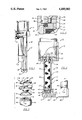
- FIG. 1 is a perspective view of a cryogenic refrigerator embodying the teachings of the present invention
- FIG. 2 is an enlarged partial view of a second stage regenerator unit utilized in the refrigerator illustrated in FIG. 1 having portions broken away to more clearly show the component parts thereof;
- FIG. 3 is an exploded perspective view of an expandable locking mechanism used to suspend the regenerator unit within an enclosing sleeve
- FIG. 4 is a further enlarged partial view end section further showing the upper section of the second stage regenerator unit containing the locking mechanism.
- the refrigerator is generally referenced 10 and includes a first expansion chamber 20 contained in the first refrigeration stage 15 and a second smaller expansion chamber 23 contained in the second refrigeration stage 17.
- the refrigerator is connected to a compressor via an inlet connector 11 and an outlet connector connector 12.
- Helium gas which is the working substance used in the present system, is provided from the discharge side of the compressor at about 300 psig and is exhausted to the suction side of the compressor at about 60 psig.
- the refrigerator has a first stage cooling capacity to about 25° K. and a second stage cooling capacity to about 7° K.
- a rotary control valve is used in the system as both a timing device and as a means for regulating the flow of refrigerant gas through the multiple stages.
- the valve is driven at a predetermined speed by means of an electric motor 13 that is housed in the upper section of the refrigerator.
- an electric motor 13 that is housed in the upper section of the refrigerator.
- the expansion chamber of the first stage is controlled by a free floating sealed displacer 18 that permits the volume of the chamber to be varied while the second stage contains a similar smaller diameter piston 22 that operates to vary the volume of chamber 23.
- the two chambers are interconnected by means of a regenerator unit 45 and an extended surface heat exchanger unit 25 that are mounted in series therebetween.
- the control valve is cycled to permit the cold high pressure gas to be exhausted into the heat exchanger unit to provide the desired final refrigeration effect bringing the temperature in this region to about 7° K.
- the gas is now passed back through the regenerator where it picks up the heat energy stored therein before being returned through the valve to the compressor.
- the low temperature heat exchanger unit 25 forms the cold head of the refrigerator and generally includes a hollow manifold section 28 of U-shaped construction and a heat exchanger, generally referenced 30.
- An opening 29 passes through the unit and provides a flow path by which the helium gas flows between stages.
- the heat exchanger itself is mounted in a recess 35 located on the first stage side of the manifold.
- the exchanger consists of a series of stacked perforated plates 31--31 which are separated by interposed wire spacers 32--32.
- the spacers are typically formed in a G-like configuration and are placed between the plates to support them in spaced apart parallel alignment within the recess.
- An expanded circular opening 42 is formed in coaxial alignment with the recess that houses the heat exchanger and is adapted to receive a sleeve 35 therein.
- the sleeve is bottomed in the opening 42 directly over the heat exchanger and is joined to the manifold using any suitable means for creating a leak tight joint therebetween.
- the opposite end of the sleeve is similarly joined to the bottom wall 40 of the first stage expansion chamber.
- This end of the sleeve contains an enlarged hub section 36 that supports a radially disposed flange 37.
- the flange is secured in a complimentary groove formed in the top of wall 40 and, as illustrated in FIG. 2, forms an entrance to the regenerator unit 45.
- the second stage regenerator unit 45 is slidably contained within the sleeve 27.
- the unit includes an elongated cylindrical housing 46 that is typically formed of a woven glass material.
- the bottom of the housing is closed by a copper plug 47 having high thermal conductivity which is tightly fitted into the housing and secured in place by means of screws or the like.
- the plug is bottomed in the opening formed in the top of the manifold 28 to position the regenerator directly over the heat exchanger 30.
- a hole 48 passes through the plug to allow refrigerant to pass freely between the regenerator and the heat exchanger.
- the regenerator housing is tightly packed with fine lead shot capable of retaining its specific heat at the low operating temperatures. Accordingly, the shot is able to extract heat from refrigerant passing from the first stage into the second stage and return the extracted heat to refrigerant moving in the opposite direction.
- the top of the regenerator housing contains a threaded opening 57 therein into which the shank 53 of end cap 50 is turned.
- the end cap in assembly, is threaded against the top surface 54 of the regenerator housing.
- a recessed shoulder 55 is formed in the outer periphery of this top surface and a deformable gasket 56 is fitted into the recess.
- the gasket is compressed between the end cap and the regenerator housing so that it is deformed radially into sealing contact against the sleeve to provide a fluid tight seal therebetween. The seal prevents refrigerant from moving between the regenerator and the sleeve and thus forces refrigerant in motion to pass through the regenerator.
- the threaded end cap 50 also includes a pair of radially disposed locking lugs 58--58 that are slidably received with a pair of coacting L-shaped guideways formed in the upper hub of the sleeve.
- the guideways are formed so that the vertical groove of each passes downwardly from the top of the sleeve to a predetermined depth.
- the horizontal groove of the guideway then passes circumferentially along the sleeve wall and is inclined slightly in a downward direction.
- the lugs are passed into the vertical legs and bottomed therein to position the bottom plug of the attached regenerator directly over the heat exchanger. Turning the end cap in the circumferential direction causes the lugs to pass into the horizontal grooves thus driving the bottom wall into locking contact against the low temperature manifold. Accordingly, negative volume is maintained between the regenerator and the low temperature heat exchanger.
- a radially expandable hanger 60 is also passed into the top opening of the sleeve and is placed in seating contact against the top surface of the threaded end cap 50.
- the hanger is basically a split collar 61 having a centrally located flow port 62 that communicates directly, in assembly, with the flow port 51 formed in the end cap to permit working fluids to move freely between the first stage expansion chamber and the regenerator unit.
- the split collar further includes a pair of countersunk holes 65-65 which lie upon a common radially disposed centerline passing through the center of the flow port 52.
- a slotted opening 66 is cut along this line so that it passes through both of the countersunk holes as well as the central port thus allowing the collar to be easily expanded in a radial direction.
- a pair of flat-head screws 67--67 (FIG. 2) are passed through the countersunk holes formed in the collar and are threaded into coaligned receiving holes 68--68 tapped in the threaded cap.
- the normally unexpanded outer diameter of the collar forms a close running fit with the inner wall of the sleeve so that when the hanger is placed over the end cap in assembly, there exists a very slight clearance between the outer periphery of the collar and the inner wall of the sleeve.
- the collar expands radially into locking contact against the inner wall of the sleeve to secure the regenerator housing inside the sleeve.
- sufficient clearance is furnished between the outside diameter of the housing and the inside diameter of the sleeve to permit the housing to thermally deform within the sleeve when exposed to the extreme changes in temperatures that take place in this region during normal machine operations.
- the regenerator unit of the present invention can be easily slipped into and out of the enclosing sleeve to provide greater ease of assembly and interchangeability of parts for maintenance purposes.
- the split collar and the sleeve are both formed of the same material. Accordingly, a uniform locking force is exerted by the collar on the sleeve at all times thereby preventing movement of the regenerator under changing thermal conditions.
- the locking lugs also serve to bottom the regenerator unit against the heat exchanger thus further preventing axial displacement of the unit.
Landscapes
- Engineering & Computer Science (AREA)
- Physics & Mathematics (AREA)
- Mechanical Engineering (AREA)
- Thermal Sciences (AREA)
- General Engineering & Computer Science (AREA)
- Separation By Low-Temperature Treatments (AREA)
Abstract
Description
Claims (9)
Priority Applications (1)
| Application Number | Priority Date | Filing Date | Title |
|---|---|---|---|
| US06/537,030 US4490983A (en) | 1983-09-29 | 1983-09-29 | Regenerator apparatus for use in a cryogenic refrigerator |
Applications Claiming Priority (1)
| Application Number | Priority Date | Filing Date | Title |
|---|---|---|---|
| US06/537,030 US4490983A (en) | 1983-09-29 | 1983-09-29 | Regenerator apparatus for use in a cryogenic refrigerator |
Publications (1)
| Publication Number | Publication Date |
|---|---|
| US4490983A true US4490983A (en) | 1985-01-01 |
Family
ID=24140883
Family Applications (1)
| Application Number | Title | Priority Date | Filing Date |
|---|---|---|---|
| US06/537,030 Expired - Fee Related US4490983A (en) | 1983-09-29 | 1983-09-29 | Regenerator apparatus for use in a cryogenic refrigerator |
Country Status (1)
| Country | Link |
|---|---|
| US (1) | US4490983A (en) |
Cited By (7)
| Publication number | Priority date | Publication date | Assignee | Title |
|---|---|---|---|---|
| US4848092A (en) * | 1987-10-02 | 1989-07-18 | Gifford Peter E | Heat exchanger for cryogenic refrigerator |
| US5113663A (en) * | 1991-03-11 | 1992-05-19 | Cryomech, Inc. | Multi-stage cryogenic refrigerator |
| US5469709A (en) * | 1993-06-18 | 1995-11-28 | Samsung Electronics Co., Ltd. | Regenerator for Vuilleumier heat pump |
| US5735127A (en) * | 1995-06-28 | 1998-04-07 | Wisconsin Alumni Research Foundation | Cryogenic cooling apparatus with voltage isolation |
| US20030192323A1 (en) * | 2002-04-10 | 2003-10-16 | Poese Mathew E. | Compliant enclosure for thermoacoustic device |
| US20030192322A1 (en) * | 2002-04-10 | 2003-10-16 | Garrett Steven L. | Cylindrical spring with integral dynamic gas seal |
| US20030192324A1 (en) * | 2002-04-10 | 2003-10-16 | Smith Robert W. M. | Thermoacoustic device |
Citations (3)
| Publication number | Priority date | Publication date | Assignee | Title |
|---|---|---|---|---|
| US2906101A (en) * | 1957-11-14 | 1959-09-29 | Little Inc A | Fluid expansion refrigeration method and apparatus |
| US3312072A (en) * | 1965-06-11 | 1967-04-04 | William E Gifford | Method and apparatus for refrigeration utilizing sterling cycle type of operation |
| US4398398A (en) * | 1981-08-14 | 1983-08-16 | Wheatley John C | Acoustical heat pumping engine |
-
1983
- 1983-09-29 US US06/537,030 patent/US4490983A/en not_active Expired - Fee Related
Patent Citations (3)
| Publication number | Priority date | Publication date | Assignee | Title |
|---|---|---|---|---|
| US2906101A (en) * | 1957-11-14 | 1959-09-29 | Little Inc A | Fluid expansion refrigeration method and apparatus |
| US3312072A (en) * | 1965-06-11 | 1967-04-04 | William E Gifford | Method and apparatus for refrigeration utilizing sterling cycle type of operation |
| US4398398A (en) * | 1981-08-14 | 1983-08-16 | Wheatley John C | Acoustical heat pumping engine |
Cited By (14)
| Publication number | Priority date | Publication date | Assignee | Title |
|---|---|---|---|---|
| US4848092A (en) * | 1987-10-02 | 1989-07-18 | Gifford Peter E | Heat exchanger for cryogenic refrigerator |
| US5113663A (en) * | 1991-03-11 | 1992-05-19 | Cryomech, Inc. | Multi-stage cryogenic refrigerator |
| US5469709A (en) * | 1993-06-18 | 1995-11-28 | Samsung Electronics Co., Ltd. | Regenerator for Vuilleumier heat pump |
| US5735127A (en) * | 1995-06-28 | 1998-04-07 | Wisconsin Alumni Research Foundation | Cryogenic cooling apparatus with voltage isolation |
| US20030192323A1 (en) * | 2002-04-10 | 2003-10-16 | Poese Mathew E. | Compliant enclosure for thermoacoustic device |
| US20030192322A1 (en) * | 2002-04-10 | 2003-10-16 | Garrett Steven L. | Cylindrical spring with integral dynamic gas seal |
| US20030192324A1 (en) * | 2002-04-10 | 2003-10-16 | Smith Robert W. M. | Thermoacoustic device |
| US6725670B2 (en) | 2002-04-10 | 2004-04-27 | The Penn State Research Foundation | Thermoacoustic device |
| US6755027B2 (en) | 2002-04-10 | 2004-06-29 | The Penn State Research Foundation | Cylindrical spring with integral dynamic gas seal |
| US6792764B2 (en) | 2002-04-10 | 2004-09-21 | The Penn State Research Foundation | Compliant enclosure for thermoacoustic device |
| US20050028535A1 (en) * | 2002-04-10 | 2005-02-10 | Poese Matthew E. | Compliant enclosure for thermoacoustic device |
| US20050274123A1 (en) * | 2002-04-10 | 2005-12-15 | The Penn State Research Foundation | Thermoacoustic device |
| US7055332B2 (en) | 2002-04-10 | 2006-06-06 | The Penn State Research Foundation | Compliant enclosure for thermoacoustic device |
| US7143586B2 (en) | 2002-04-10 | 2006-12-05 | The Penn State Research Foundation | Thermoacoustic device |
Similar Documents
| Publication | Publication Date | Title |
|---|---|---|
| EP0372029B1 (en) | Regenerative cryogenic refrigerator | |
| EP0864826B1 (en) | Expansion valve | |
| US4333755A (en) | Cryogenic apparatus | |
| US4490983A (en) | Regenerator apparatus for use in a cryogenic refrigerator | |
| US4397156A (en) | Displacer for low-temperature refrigerating machines | |
| US4310337A (en) | Cryogenic apparatus | |
| US4305741A (en) | Cryogenic apparatus | |
| US3321926A (en) | Fluid-actuated cryogenic refrigerator | |
| US4294600A (en) | Valves for cryogenic refrigerators | |
| US4388809A (en) | Cryogenic refrigerator | |
| JP3874866B2 (en) | Method for forming thermal interface gaskets and thermal joints | |
| KR102461067B1 (en) | Scroll compressor and air conditioner having this | |
| CA1247873A (en) | Linear motor compressor with pressure stabilization ports for use in refrigeration systems | |
| US4520630A (en) | Cryogenic refrigerator and heat source | |
| US4438631A (en) | Cryogenic refrigerator | |
| US4522033A (en) | Cryogenic refrigerator with gas spring loaded valve | |
| US5036670A (en) | Cryogenic refrigerator with corner seal | |
| US4294077A (en) | Cryogenic refrigerator with dual control valves | |
| US3969907A (en) | Cold cylinder assembly for cryogenic refrigerator | |
| US4848092A (en) | Heat exchanger for cryogenic refrigerator | |
| US4481777A (en) | Cryogenic refrigerator | |
| EP0399813B1 (en) | Cryogenic refrigerator | |
| WO2023076043A1 (en) | Gas energized seal for gifford-mcmahon expander | |
| US4708165A (en) | High pressure stepped clearance seal valve in a cryogenic refrigeration system | |
| JPH0714773Y2 (en) | Cryogenic refrigerator |
Legal Events
| Date | Code | Title | Description |
|---|---|---|---|
| AS | Assignment |
Owner name: CRYOMECH INC., 1630 ERIE BLVD., E., SYRACUSE A NE Free format text: ASSIGNMENT OF ASSIGNORS INTEREST.;ASSIGNORS:GIFFORD, PETER E.;SWIFT, STEPHEN D.;REEL/FRAME:004316/0765 Effective date: 19830923 Owner name: CRYOMECH INC., A NEW YORK CORP.,NEW YORK Free format text: ASSIGNMENT OF ASSIGNORS INTEREST;ASSIGNORS:GIFFORD, PETER E.;SWIFT, STEPHEN D.;REEL/FRAME:004316/0765 Effective date: 19830923 |
|
| FPAY | Fee payment |
Year of fee payment: 4 |
|
| FPAY | Fee payment |
Year of fee payment: 8 |
|
| FEPP | Fee payment procedure |
Free format text: PAYOR NUMBER ASSIGNED (ORIGINAL EVENT CODE: ASPN); ENTITY STATUS OF PATENT OWNER: SMALL ENTITY |
|
| REMI | Maintenance fee reminder mailed | ||
| LAPS | Lapse for failure to pay maintenance fees | ||
| FP | Lapsed due to failure to pay maintenance fee |
Effective date: 19970101 |
|
| STCH | Information on status: patent discontinuation |
Free format text: PATENT EXPIRED DUE TO NONPAYMENT OF MAINTENANCE FEES UNDER 37 CFR 1.362 |