US4489846A - Self-leveling base for tank - Google Patents
Self-leveling base for tank Download PDFInfo
- Publication number
- US4489846A US4489846A US06/539,682 US53968283A US4489846A US 4489846 A US4489846 A US 4489846A US 53968283 A US53968283 A US 53968283A US 4489846 A US4489846 A US 4489846A
- Authority
- US
- United States
- Prior art keywords
- head
- tank
- base
- wall
- skirt
- Prior art date
- Legal status (The legal status is an assumption and is not a legal conclusion. Google has not performed a legal analysis and makes no representation as to the accuracy of the status listed.)
- Expired - Lifetime
Links
Images
Classifications
-
- B—PERFORMING OPERATIONS; TRANSPORTING
- B65—CONVEYING; PACKING; STORING; HANDLING THIN OR FILAMENTARY MATERIAL
- B65D—CONTAINERS FOR STORAGE OR TRANSPORT OF ARTICLES OR MATERIALS, e.g. BAGS, BARRELS, BOTTLES, BOXES, CANS, CARTONS, CRATES, DRUMS, JARS, TANKS, HOPPERS, FORWARDING CONTAINERS; ACCESSORIES, CLOSURES, OR FITTINGS THEREFOR; PACKAGING ELEMENTS; PACKAGES
- B65D90/00—Component parts, details or accessories for large containers
- B65D90/12—Supports
Definitions
- Tanks such as water softeners, water heaters, water filters, iron filters, hydropneumatic tanks, and the like, generally have dome-shaped lower heads.
- a plurality of legs or alternately, an annular skirt, are connected to the lower head and serve to support the tank from the floor or other supporting surface.
- shims are inserted under the legs to provide the level condition.
- annular skirt a series of stepped wedge-shaped blocks are inserted beneath the skirt at various locations around the circumference of the skirt to level the tank. As the use of the wedges results in high stress concentrations in the skirt directly above the wedges, it is the normal instructional procedure to support at least 50% of the circumference of the skirt or base with wedges.
- supporting legs are normally welded to the tank and are occasionally broken or bent during shipment and handling. Furthermore, as the legs are normally metal, they are subjected to corrosion, particularly when the tank is used in a moist environment.
- the invention is directed to a self-leveling supporting base for a tank.
- the base includes a tapered annular skirt having an upper annular rim disposed in contact with the lower dome-shaped head of the tank and the lower edge of the skirt is adapted to rest on the supporting surface.
- a downwardly curved wall which extends across the skirt and is spaced beneath the head of the tank.
- the curved wall is provided with an opening to receive a fluid outlet nipple which extends axially from the head.
- the lower end of the nipple receives a washer and a threaded connector, such as a fitting, and by turning down the connector, the curved wall will be deformed upwardly to urge the rim into tight engagement with the head of the tank.
- the opening in the curved wall is considerably larger than the outlet nipple and on installation of the tank at its site of use, the base can be moved relative to the tank to insure that the tank is properly positioned in an upright condition regardless of the uneveness of the supporting surface.
- One or more annular flexible lips extend upwardly adjacent the rim and engage the dome-shaped head of the tank.
- the lips serve to provide a seal to prevent condensate from dripping downwardly along the tank into the interior of the base and the lips also increase the frictional resistance between the base and the tank head to thereby maintain the tank in the desired orientation with respect to the base.
- the tank-supporting base of the invention is installed at the factory and it is merely necessary at the site of use to shift the base laterally, if necessary, to provide the proper upright alignment for the tank. No tools are required to install the tank in its proper upright condition and no auxiliary parts are required for the installation.
- the base is preferably formed of a non-corrosive plastic material, such as molded polyethylene and as such, it is not only inexpensive to produce, but it is extremely durable and will aid in protecting the tank during shipment and handling.
- the base can be used with all types of tanks having a dome-shaped head, such as water heaters, water softeners, water filters, iron filters, hydropneumatic tanks, and the like.
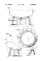
- FIG. 1 is a vertical section of the self-leveling base of the invention as applied to a tank;
- FIG. 2 is a bottom view of the base shown in FIG. 1;
- FIG. 3 is an enlarged fragmentary vertical section showing the lips on the base.
- FIG. 4 is a vertical section of a modified form of the invention.
- FIG. 1 illustrates a self-leveling supporting base 1 for a tank 2.
- the tank can be any type of a tank which is normally positioned in an upright condition and can include a water softener tank, a water heater tank, a water filter tank, hydropneumatic tank, and the like.
- the tank 2 includes a generally cylindrical shell 3 which is enclosed at its lower end by a dome-shaped head 4.
- a nipple or tube 5 is secured centrally within an opening in head 4 and serves as either an entry or discharge conduit for fluid contained within the tank.
- the base 1 comprises an upwardly tapering skirt 6 having an annular lower edge 7 which is adapted to rest on a supporting surface 8.
- the upper edge of skirt 6 defines an annular rim 9 which is disposed in contact with the outer surface of head 4 of tank 2.
- Skirt 6 is preferably formed from a molded plastic material, such as polyethylene and to provide added strength and rigidity, a series of ribs 10 can be formed in the skirt.
- base 1 also includes a downwardly curved internal wall 11, which is spaced beneath head 4. As illustrated in FIG. 2, the wall 11 has a lesser radius of curvature than the head 4, and is spaced a substantial distance beneath the head.
- opening 12 Formed centrally of wall 11 is an opening 12 which receives nipple 5. As shown in FIG. 4, the diameter of opening 12 is substantially greater than the outer diameter of nipple 5, so that the entire base 1 can be shifted laterally relative to the tank head 4.
- a washer 13 which has a larger outer diameter than the diameter of opening 12, is engaged with the lower surface of wall 11, and elbow 14 is threaded on the lower end of nipple 5.
- a pipe 15 is threaded with the elbow 14 and extends through a hole 16 in skirt 6.
- one or more annular lips 17 are formed in rim 9. Lips 17 are flexible and bear against the lower surface of head 4 to provide a seal between tank 2 and base 1, thereby preventing condensation or other liquid from running downwardly into the interior of the base 1. Alternately, if lips 17 are not employed in rim 9, suitable drain holes can be formed in the curved wall 11, outwardly of the central opening 12 for drainage.
- Base 1 is fully installed with tank 2 at the factory, with elbow 14 being threaded on the lower end of nipple 5. At the location of use, the installer merely lifts the tank so that the base 1 is above the ground and then can kick, or otherwise move, the base to shift it laterally relative to the tank to provide the desired alignment so that the tank will be installed in an upright condition.
- FIG. 4 illustrates a modified form of the invention in which the tank 2 does not have a fluid conduit in the lower dome-shaped head 4, but instead, the fluid openings are either in the shell or in the upper head.
- a nut 18 is welded centrally of the lower head 4 and a bolt 19 is inserted through washer 13, as well as through openings 12 in wall 11, and is threaded with the nut 18.
- the rim 9 will be drawn into tight engagement with the lower head 4 of the tank 2 as previously described.
- the base 1 As the base 1 is assembled with the tank at the factory, the base will aid in protecting the tank during shipment and handling. As a further advantage, no tools or auxiliary parts or fasteners are required in leveling the tank at the site of installation.
- the base is preferably formed of a molded thermoplastic material, it is inexpensive to produce, extremely durable and provides an attractive appearance for the tank.
Abstract
Description
Claims (9)
Priority Applications (2)
| Application Number | Priority Date | Filing Date | Title |
|---|---|---|---|
| US06/539,682 US4489846A (en) | 1983-10-06 | 1983-10-06 | Self-leveling base for tank |
| CA000464446A CA1231903A (en) | 1983-10-06 | 1984-10-01 | Self-leveling base for tank |
Applications Claiming Priority (1)
| Application Number | Priority Date | Filing Date | Title |
|---|---|---|---|
| US06/539,682 US4489846A (en) | 1983-10-06 | 1983-10-06 | Self-leveling base for tank |
Publications (1)
| Publication Number | Publication Date |
|---|---|
| US4489846A true US4489846A (en) | 1984-12-25 |
Family
ID=24152223
Family Applications (1)
| Application Number | Title | Priority Date | Filing Date |
|---|---|---|---|
| US06/539,682 Expired - Lifetime US4489846A (en) | 1983-10-06 | 1983-10-06 | Self-leveling base for tank |
Country Status (2)
| Country | Link |
|---|---|
| US (1) | US4489846A (en) |
| CA (1) | CA1231903A (en) |
Cited By (11)
| Publication number | Priority date | Publication date | Assignee | Title |
|---|---|---|---|---|
| US4620685A (en) * | 1983-11-11 | 1986-11-04 | Suntory Limited | Rotating mechanism attachable to bottom of container |
| US4932621A (en) * | 1988-08-12 | 1990-06-12 | Ronald Kowk | Support base for propane tanks |
| US5085387A (en) * | 1991-03-08 | 1992-02-04 | Quake Safe Corporation | Water heater support system |
| US5131133A (en) * | 1991-03-08 | 1992-07-21 | Quake Safe Corp. | Water heater support system and methods |
| US6571976B1 (en) * | 2000-11-15 | 2003-06-03 | Gene H. Sonnabend | Insulated container sleeve with suction base |
| US7726620B1 (en) * | 2008-02-21 | 2010-06-01 | Bruce Kleespie | Vertical fuel tank support system |
| EP2669567A1 (en) * | 2013-05-30 | 2013-12-04 | MT Aerospace AG | Device for receiving and storing a container and a storage assembly and their use |
| US20140231439A1 (en) * | 2010-10-04 | 2014-08-21 | Amtrol Licensing, Inc. | Plastic stand and method of attachment to a pressure vessel |
| US20140262992A1 (en) * | 2013-03-15 | 2014-09-18 | Hearth Products Controls | Water basin and system |
| EP2283273A4 (en) * | 2008-05-08 | 2017-12-27 | AMTROL Licensing Inc. | Support stand for pressure vessel |
| JP2019007205A (en) * | 2017-06-23 | 2019-01-17 | 三菱重工業株式会社 | Reinforcement method and support structure of container |
Citations (10)
| Publication number | Priority date | Publication date | Assignee | Title |
|---|---|---|---|---|
| US1449974A (en) * | 1920-12-08 | 1923-03-27 | Alvie C Crimmel | Bin for sugar and the like |
| US1810774A (en) * | 1928-09-13 | 1931-06-16 | James H Mackley | Water heater |
| US2062589A (en) * | 1935-09-16 | 1936-12-01 | John W Lucas | Container for carbon dioxide blocks |
| US2067581A (en) * | 1935-04-12 | 1937-01-12 | American La France Foamite | Cushion flask base |
| US2954636A (en) * | 1958-04-16 | 1960-10-04 | Richard J Gammache | Universal furniture foot construction |
| US3022969A (en) * | 1958-09-16 | 1962-02-27 | Licentia Gmbh | Ventilator |
| US3497101A (en) * | 1967-01-31 | 1970-02-24 | Hideo Sagara | Multi-layer container |
| US3840141A (en) * | 1972-04-17 | 1974-10-08 | Gkn Sankey Ltd | Containers for liquids |
| US3851626A (en) * | 1972-10-05 | 1974-12-03 | Westinghouse Electric Corp | Support for a steam generator |
| US4161426A (en) * | 1975-12-23 | 1979-07-17 | Gebruder Weiss Kg | Apparatus for removing gaseous impurities |
-
1983
- 1983-10-06 US US06/539,682 patent/US4489846A/en not_active Expired - Lifetime
-
1984
- 1984-10-01 CA CA000464446A patent/CA1231903A/en not_active Expired
Patent Citations (10)
| Publication number | Priority date | Publication date | Assignee | Title |
|---|---|---|---|---|
| US1449974A (en) * | 1920-12-08 | 1923-03-27 | Alvie C Crimmel | Bin for sugar and the like |
| US1810774A (en) * | 1928-09-13 | 1931-06-16 | James H Mackley | Water heater |
| US2067581A (en) * | 1935-04-12 | 1937-01-12 | American La France Foamite | Cushion flask base |
| US2062589A (en) * | 1935-09-16 | 1936-12-01 | John W Lucas | Container for carbon dioxide blocks |
| US2954636A (en) * | 1958-04-16 | 1960-10-04 | Richard J Gammache | Universal furniture foot construction |
| US3022969A (en) * | 1958-09-16 | 1962-02-27 | Licentia Gmbh | Ventilator |
| US3497101A (en) * | 1967-01-31 | 1970-02-24 | Hideo Sagara | Multi-layer container |
| US3840141A (en) * | 1972-04-17 | 1974-10-08 | Gkn Sankey Ltd | Containers for liquids |
| US3851626A (en) * | 1972-10-05 | 1974-12-03 | Westinghouse Electric Corp | Support for a steam generator |
| US4161426A (en) * | 1975-12-23 | 1979-07-17 | Gebruder Weiss Kg | Apparatus for removing gaseous impurities |
Cited By (13)
| Publication number | Priority date | Publication date | Assignee | Title |
|---|---|---|---|---|
| US4620685A (en) * | 1983-11-11 | 1986-11-04 | Suntory Limited | Rotating mechanism attachable to bottom of container |
| US4932621A (en) * | 1988-08-12 | 1990-06-12 | Ronald Kowk | Support base for propane tanks |
| US5085387A (en) * | 1991-03-08 | 1992-02-04 | Quake Safe Corporation | Water heater support system |
| US5131133A (en) * | 1991-03-08 | 1992-07-21 | Quake Safe Corp. | Water heater support system and methods |
| US6571976B1 (en) * | 2000-11-15 | 2003-06-03 | Gene H. Sonnabend | Insulated container sleeve with suction base |
| US7726620B1 (en) * | 2008-02-21 | 2010-06-01 | Bruce Kleespie | Vertical fuel tank support system |
| EP2283273A4 (en) * | 2008-05-08 | 2017-12-27 | AMTROL Licensing Inc. | Support stand for pressure vessel |
| US20140231439A1 (en) * | 2010-10-04 | 2014-08-21 | Amtrol Licensing, Inc. | Plastic stand and method of attachment to a pressure vessel |
| US9528659B2 (en) * | 2010-10-04 | 2016-12-27 | Amtrol Licensing Inc. | Plastic stand and method of attachment to a pressure vessel |
| US9192881B2 (en) * | 2013-03-15 | 2015-11-24 | Hearth Products Controls Co. | Water basin and system |
| US20140262992A1 (en) * | 2013-03-15 | 2014-09-18 | Hearth Products Controls | Water basin and system |
| EP2669567A1 (en) * | 2013-05-30 | 2013-12-04 | MT Aerospace AG | Device for receiving and storing a container and a storage assembly and their use |
| JP2019007205A (en) * | 2017-06-23 | 2019-01-17 | 三菱重工業株式会社 | Reinforcement method and support structure of container |
Also Published As
| Publication number | Publication date |
|---|---|
| CA1231903A (en) | 1988-01-26 |
Similar Documents
| Publication | Publication Date | Title |
|---|---|---|
| US4489846A (en) | Self-leveling base for tank | |
| US5271518A (en) | Sump cover | |
| US4344645A (en) | Tee-type leg bracket | |
| US5806702A (en) | Ribbed storage tank | |
| US6318581B1 (en) | Discharge outlet for double wall containment tank assembly | |
| US5117877A (en) | Overfill assembly made of polymeric material | |
| US4983285A (en) | Individual wastewater treatment plant | |
| US3913400A (en) | Plastic meter box | |
| US4313457A (en) | Removable condensate collector for elevated water storage facilities | |
| US4515398A (en) | Device for elevating closet bowl | |
| US3319268A (en) | Water closet coupling | |
| US5505327A (en) | Flexible lined tank with vacuum in the manway | |
| US4423527A (en) | Fabricated floor drain with combination anchoring and seepage control flange | |
| CA2650296A1 (en) | Storage tank with self-draining full-contact floating roof | |
| US5372453A (en) | Fuel spill containment device | |
| US5474396A (en) | Watertight sealing system for manhole | |
| US6135410A (en) | Retrofit pan and water heater stand | |
| US6474496B1 (en) | Containment tank assembly | |
| US4450855A (en) | Removable condensate collector for elevated water storage facilities | |
| WO1998057087A1 (en) | Pipe threaded joint assembly | |
| US6206228B1 (en) | Double-walled tank for storing fluids such as heating-oil, and the like | |
| US5833392A (en) | One-piece tank sump with integral dust cover | |
| US5217052A (en) | Containment assembly for fill pipe of underground storage tanks | |
| US1721472A (en) | Self-clearing roof-drain strainer | |
| US5501243A (en) | Liquid storage tank sump |
Legal Events
| Date | Code | Title | Description |
|---|---|---|---|
| AS | Assignment |
Owner name: A.O. SMITH CORPORATION MILWAUKEE, WI A CORP OF NY Free format text: ASSIGNMENT OF ASSIGNORS INTEREST.;ASSIGNOR:NICKEL, HERBERT W.;REEL/FRAME:004183/0504 Effective date: 19830915 |
|
| STCF | Information on status: patent grant |
Free format text: PATENTED CASE |
|
| FEPP | Fee payment procedure |
Free format text: PAYOR NUMBER ASSIGNED (ORIGINAL EVENT CODE: ASPN); ENTITY STATUS OF PATENT OWNER: LARGE ENTITY |
|
| FPAY | Fee payment |
Year of fee payment: 4 |
|
| AS | Assignment |
Owner name: AOS HOLDING COMPANY, DELAWARE Free format text: ASSIGNMENT OF ASSIGNORS INTEREST.;ASSIGNOR:A. O. SMITH CORPORATION, A CORP. OF DE;REEL/FRAME:005253/0894 Effective date: 19891211 |
|
| FEPP | Fee payment procedure |
Free format text: PAYER NUMBER DE-ASSIGNED (ORIGINAL EVENT CODE: RMPN); ENTITY STATUS OF PATENT OWNER: LARGE ENTITY Free format text: PAYOR NUMBER ASSIGNED (ORIGINAL EVENT CODE: ASPN); ENTITY STATUS OF PATENT OWNER: LARGE ENTITY |
|
| FPAY | Fee payment |
Year of fee payment: 8 |
|
| FPAY | Fee payment |
Year of fee payment: 12 |