US448317A - Charles e - Google Patents
Charles e Download PDFInfo
- Publication number
- US448317A US448317A US448317DA US448317A US 448317 A US448317 A US 448317A US 448317D A US448317D A US 448317DA US 448317 A US448317 A US 448317A
- Authority
- US
- United States
- Prior art keywords
- iron
- plate
- heated
- heat
- secured
- Prior art date
- Legal status (The legal status is an assumption and is not a legal conclusion. Google has not performed a legal analysis and makes no representation as to the accuracy of the status listed.)
- Expired - Lifetime
Links
- XEEYBQQBJWHFJM-UHFFFAOYSA-N Iron Chemical compound [Fe] XEEYBQQBJWHFJM-UHFFFAOYSA-N 0.000 description 54
- 229910052742 iron Inorganic materials 0.000 description 31
- 238000009413 insulation Methods 0.000 description 9
- 239000004020 conductor Substances 0.000 description 7
- 238000010438 heat treatment Methods 0.000 description 4
- 230000005855 radiation Effects 0.000 description 4
- 208000027418 Wounds and injury Diseases 0.000 description 2
- 230000006378 damage Effects 0.000 description 2
- 208000014674 injury Diseases 0.000 description 2
- 239000011810 insulating material Substances 0.000 description 2
- 210000000988 bone and bone Anatomy 0.000 description 1
- 230000000694 effects Effects 0.000 description 1
- 238000005485 electric heating Methods 0.000 description 1
- 238000010292 electrical insulation Methods 0.000 description 1
- 229910052500 inorganic mineral Inorganic materials 0.000 description 1
- 150000002500 ions Chemical class 0.000 description 1
- 239000000463 material Substances 0.000 description 1
- 239000011707 mineral Substances 0.000 description 1
- 239000000615 nonconductor Substances 0.000 description 1
- 230000011514 reflex Effects 0.000 description 1
- 239000007787 solid Substances 0.000 description 1
Images
Classifications
-
- D—TEXTILES; PAPER
- D06—TREATMENT OF TEXTILES OR THE LIKE; LAUNDERING; FLEXIBLE MATERIALS NOT OTHERWISE PROVIDED FOR
- D06F—LAUNDERING, DRYING, IRONING, PRESSING OR FOLDING TEXTILE ARTICLES
- D06F75/00—Hand irons
- D06F75/38—Sole plates
Definitions
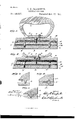
- A indicates a heated surface-plate
- B an electrical conductor or resistance, prefance or electrical conductor is employed as a erably composed of reflex iron wire
- C an means for heating the surface or workingelectrical insulation interposed between the plate of the iron, but is more especially deresistance and theheated surfaceplate, which signed as an improvement upon the invenshould, however, be a fairly good conductor 65 i 5 tionset forth in United States Letters Patof heat
- D an electrical insulation, which ent Nosn 15,856 and 429,859, granted me on should preferablybe a non-conductor of heat, the 26th day of iTovember, 1880, and 3d of in the shape of
- the prime object of this invention is to retween the resistance and a pressure-plate E, 7o zo symbolize to the minimum the wastage of energy secured by screws F or in any other suitable due to conduction or radiation of the heat manner to the surface-plates A, thus serving evolved from the resistance by confining the to bind the resistance and the respective inheat to the surface or working-plate by which sulations upon the heated surface-plate. 11.11@ Legt is to be used.
- Another object is to prevent as far as pracis similar to that illustrated in my aforesaid ticable the conduction of heat from the heated application and could, it desired, be employed portion of the iron to the top or cover and the as an iron by attaching a handle directly to handle thereof, and thereby .not only effect the compressing-plate, but such a structure economy in.
- the body or non-heated portion of the iron Similar letters of reference indicate the is attached to the heated portion of the iron, same parts in the several figures of the drawbut preferably has contact with the compressroo 50 ings, ing-plate alone by means of a screw I work- So far as relates to the means employed for ing loosely through a perforation in the body fore in order to reduce the contacting surface between the body and the compressingl plate I provide several equivalent ⁇ forms of connection therebetween. The first of these, illustrated in detail in Fig.
- the contacting surfaces are reduced to the minimum and likewise the conduction ofE heat from the compressing-plate to the body.
- connection may also be interposed between the handle Q and thebody, to which it is secured by the screw R in substantially the same manner as the body is secured to the compressing-plate, for the purpose of reducing the temperature of the handle to the minimum.
- the balls and cubes--v may have the advantage ⁇ of being composed of some hard non-conducting material which will Vgreatly impair the conduction of heat thereby.
- the heated portion of the iron is meant that .portion to which the heat is directly applied-that is, vthe heated Isurface or working-plate thereof ⁇ and suchk other port-'ions of the iron as are lconnected therewith or related thereto so in.-
Landscapes
- Engineering & Computer Science (AREA)
- Textile Engineering (AREA)
- Irons (AREA)
Description
UNITED STATES PATENT OrEIcE.
CHARLES E. CARPENTER, OF MINNEAPOLIS, MINNESOTA, ASSIGNOR TO THE CARPENTER-YEVEYS ELECTRO-HEATING COMPANY, OE SAME PLACE.
ELECTREC SAD-IRONs SPECIFICATION forming part of Letters Patent No. 448,317', dated March 1*?, 1891.
Application filed June 2l, 1890. Serial No, 356,201. (No model.)
To all when?, t may concern: heating the iron those shown in the drawings Be it known that I, CHARLES E. CARPEN- are substantially the same as in my aforesaid 'rER,a citizen of the United States, and aresipatent; but in this invent-ion are included dent of the city of Minneapolis, in the county elements capable of use in connection with 5 5 of Hennepin and State of Minnesota, have other forms of electric-heating apparatus,
invented certain new and useful Improveeither similar in structure or ditfering matements in Electric Sad-Irons, of which the folrially in the mode of heating. lowing is a specification. Referring by letter to the accompanying This invention relates to improvements in drawings, A indicates a heated surface-plate; 6o To electric sad-irons,in which an inclosed resist- B, an electrical conductor or resistance, prefance or electrical conductor is employed as a erably composed of reflex iron wire; C, an means for heating the surface or workingelectrical insulation interposed between the plate of the iron, but is more especially deresistance and theheated surfaceplate, which signed as an improvement upon the invenshould, however, be a fairly good conductor 65 i 5 tionset forth in United States Letters Patof heat; D, an electrical insulation, which ent Nosn 15,856 and 429,859, granted me on should preferablybe a non-conductor of heat, the 26th day of iTovember, 1880, and 3d of in the shape of a card of asbestus, to which June, 1890, respectively. the resistance is secured, and interposed be- The prime object of this invention is to retween the resistance and a pressure-plate E, 7o zo duce to the minimum the wastage of energy secured by screws F or in any other suitable due to conduction or radiation of the heat manner to the surface-plates A, thus serving evolved from the resistance by confining the to bind the resistance and the respective inheat to the surface or working-plate by which sulations upon the heated surface-plate. 11.11@ Legt is to be used. So much of the iron as has been described 75 2- Another object is to prevent as far as pracis similar to that illustrated in my aforesaid ticable the conduction of heat from the heated application and could, it desired, be employed portion of the iron to the top or cover and the as an iron by attaching a handle directly to handle thereof, and thereby .not only effect the compressing-plate, but such a structure economy in. the use ol the iron, but at the would be wasteful of energy, because the com- SO 3o saine time avoid all disagreeable conscpressing-plate lies so close to the heated requences of accidental Contact between the sistance that its temperature will be very high hand of the user and the top or handle of the when in use, notwithstanding the insulation iron, as well as injury to goods with which interposed therebetween, and with so much' the iron may be accidentally brought in consurface exposed much heat would be lost by 85 35 met, dissipation or radiation into the atmosphere. These objects are attained by the devices To avoid this objection I provide a cover or illustrated. in the accompanying drawings, in body G, recessed upon the inner or under side which@ thereof, as shown, leaving thin walls around Figurel represents a centralvertical section the sides and ends ol just sufficient thick- 9o 4o through a sad-iron involving my invention; ness to withstand mechanical injury and still Fig. 2, a similar view showing a modified form form a rigid structure. This recess is partly of connection between the heated and noniilled with some heat-non-coinlucting mateheated portions of the iron; and Figs. 3, 4, rial lfl`-such as loose asbestus or mineral and 5, enlarged views of several forms of conwool-to prevent the radiation and conduc- 9 5 45 nections between the heated and non-heated tion of heat from the compressing-plate to portions of the iron for reducing the contactthe body of the iron. ing area between said members. The body or non-heated portion of the iron Similar letters of reference indicate the is attached to the heated portion of the iron, same parts in the several figures of the drawbut preferably has contact with the compressroo 50 ings, ing-plate alone by means of a screw I work- So far as relates to the means employed for ing loosely through a perforation in the body fore in order to reduce the contacting surface between the body and the compressingl plate I provide several equivalent` forms of connection therebetween. The first of these, illustrated in detail in Fig. 3, consists of a conical projection K upon the body, fittingl into a conical depression L in the compressing-plate, the sides .of the cone K being of sufficiently greater degree than .the sides of A the recess to avoid contact therewith except at the point or apex of the-cone.
plate are shown as provided with conical recesses M, into which -fits a ball N of some' suitable material, while in Fig. 5 the depressions or recesses O in the body and compressing-plate are preferably concave 'and have 'fitted therein `a cube 3P of bone or som-eotheu insulating material. In all these forms lof connection while the body is rigidly supported against the pressure of the screw I and at three or more points, as may be 'desirable, the contacting surfaces are reduced to the minimum and likewise the conduction ofE heat from the compressing-plate to the body.
The connection illustrated in Figs. l and 8,
however, is preferred, because it avoids theemployment of loose or detachable parts and provides the least possible contacting, area between the parts; but the other formsshown have proved to be practically successful.
The same form of connections may also be interposed between the handle Q and thebody, to which it is secured by the screw R in substantially the same manner as the body is secured to the compressing-plate, for the purpose of reducing the temperature of the handle to the minimum.
From the foregoing it will be readily seen that with this structure vthe two parts of the iron-that is, the heated and the non-heated parts-may be held lirmly together, but still separated, excepting the very small surface of contact through the cones or other vdevices just described, thus leaving the utens'iipracticallv as firm and solid as if no such yconnections were employed. y
While the cone connection represented in y Fig. l possesses the advantage of'economy, because the cones and lcavities may be cast and the parts put together without'tools, the
other forms-that is, the balls and cubes--v may have the advantage `of being composed of some hard non-conducting material which will Vgreatly impair the conduction of heat thereby.
In either of the structures described when the cones or balls or cubes areonce in place and drawn together by the fastening-screws all motion, either horizontal or otherwise, of thefh'eated and non-heated portions of the body with relation to each other is prevented, since the parts cannot move until the screws have been loosened up and the points or cubes removed from their normal position.
Obviously the location of the cone and recess in the preferred connection (illustrated in Figs. 1 and 3) may be reversed-that is, the cone may be placed upon the compressing-plate land the cavity be formed in the body or covering-plate-Without departing from the spirit of my invention.
The number of joints in this structure of iron as well as thesmall surface of contact between the various portions thereof proves .most economical in the use of the iron., kfor 'they serve to so impair the conduction of heat f from the heated to the non-heated Aporti-ons In Fig. It the body and 'the compressing of the iron and the consequent dissipation 'thereof by radiation as to reduce the amount of energy'required in heating the iron Yand imaintaini'ng'it ata/uniform heat to the minimum. Y
In the claims inl referring to the heated portion of the iron is meant that .portion to which the heat is directly applied-that is, vthe heated Isurface or working-plate thereof `and suchk other port-'ions of the iron as are lconnected therewith or related thereto so in.-
timately as to lbe heated by conduction'fro-m v the surface-plat'e.
Having thus described my invention, what .I claim, and desire to secure by Letters Patent, is-
1. In an electric sad-iron, the combination, with the heated surface-plate anda compressingplate secured thereto, of an velectrical relsistance'or conductor interposed between said plates and an insulation interposed between said resistance and each of sa'idplates, lsub stantially as described. Y v
2. In an electric sad-iron, the combination, with the heated surface-plate, the compress.- ing-plate secured thereto, an Aelect-rical conductor or resist-ance located between said plates, andan insulation interposed between said resistance and each of ksaid plates, vof 'a body secured to the compressing-plate and a filling of heat-insulating material between said body and plates, substantially as -described.
3. In an electric'sad-iron, the combination, with the heated surface-plate, 'the compressing-plate secured thereto, an electrical 'conld-uctor or resistance located between said plates, and an insulation interposed between said resistance and each 'of said plates, of a with the heated 'surface-plate, the compress ing-plate secured' thereto, an electrical conductor or resistance located between 'said plates, and an insulation interposed between IOO IIO
said resistance and each of said plates, of a cover or body secured to the compressing`- plate, a cone-and-socket connection or its equivalent between said body and plate, and a heat-insulation interposed between said body and plate, substantially as described.
5. In an electric sad-iron, the combination, with the heated port-ion thereof, of the body or cover secured thereto and a cone-andsocket connection or its equivalent between said body and the heated portion, substantially as described.
G. In an electric sad-iron, the combination, with the heated portion thereof, of a cover or body secured thereto, a cone-and-socket connection or its equivalent between said body and the heated portion, and a filling of heatinsulation between said body and the heated portion, substantially as described.
'7. In an electric sad-iron, the combination, with the heated portion thereof, of a cover or body secured to said heated portion, a handle secured to said body, and a cone-and-socket connection or its equivalentbetween said body and the heated portion of the iron and between said body and handle, substantially as described.
8. In an electric sad-iron, the combination, with the heated portion of the iron, the body, a screw working loosely through the body and engaging the heated portion, a heat-insulation between said screw and body, the handle, a screw working loosely through said handle and engaging the body, anda heat-insulation between said screw and handle, of a cone-andsoeket connection or its equivalent between said body and the heated portion of the iron and between said body and the handle, substantially as described.
In testimony whereof I affix my signature in 4o presence of two witnesses.
CHARLES E. CARPENTER.
IVitnesses:
W. F. UsTIoK, Roer. T. LANG.
Publications (1)
| Publication Number | Publication Date |
|---|---|
| US448317A true US448317A (en) | 1891-03-17 |
Family
ID=2517203
Family Applications (1)
| Application Number | Title | Priority Date | Filing Date |
|---|---|---|---|
| US448317D Expired - Lifetime US448317A (en) | Charles e |
Country Status (1)
| Country | Link |
|---|---|
| US (1) | US448317A (en) |
-
0
- US US448317D patent/US448317A/en not_active Expired - Lifetime
Similar Documents
| Publication | Publication Date | Title |
|---|---|---|
| US448317A (en) | Charles e | |
| US798457A (en) | Self galvanic massage apparatus. | |
| US415856A (en) | Charles e | |
| US1494939A (en) | Electric heater | |
| US743473A (en) | Cold compress. | |
| US1021230A (en) | Electric heater. | |
| US477627A (en) | Charles e | |
| US1551868A (en) | Method of the application and construction of electrical heating units | |
| US1476376A (en) | Electric heater | |
| US890858A (en) | Electric heating device. | |
| US686080A (en) | Sad-iron. | |
| US534699A (en) | Electric resistance-card | |
| US436119A (en) | Charles e | |
| US1158487A (en) | Resistance element. | |
| US1157343A (en) | Electrically-heated tool. | |
| US966703A (en) | Electric sad-iron. | |
| US497792A (en) | jenkins | |
| US1206392A (en) | Electric water-heater. | |
| US429559A (en) | Charles e | |
| US439724A (en) | Charles w | |
| US1612220A (en) | Electrically-heated branding iron | |
| US566545A (en) | Electric heating apparatus | |
| US1114413A (en) | Electric sad-iron. | |
| US918747A (en) | Electrically-operated stove. | |
| US566693A (en) | Harry ward leonard |