US4479597A - Burster for continuous form stationery - Google Patents
Burster for continuous form stationery Download PDFInfo
- Publication number
- US4479597A US4479597A US06/466,814 US46681483A US4479597A US 4479597 A US4479597 A US 4479597A US 46681483 A US46681483 A US 46681483A US 4479597 A US4479597 A US 4479597A
- Authority
- US
- United States
- Prior art keywords
- stop
- burster
- stop members
- shaft
- tooth
- Prior art date
- Legal status (The legal status is an assumption and is not a legal conclusion. Google has not performed a legal analysis and makes no representation as to the accuracy of the status listed.)
- Expired - Lifetime
Links
- 230000015572 biosynthetic process Effects 0.000 claims description 8
- 229920003023 plastic Polymers 0.000 claims description 5
- 239000004033 plastic Substances 0.000 claims description 5
- 230000006835 compression Effects 0.000 claims description 2
- 238000007906 compression Methods 0.000 claims description 2
- 238000005755 formation reaction Methods 0.000 claims 3
- 230000003116 impacting effect Effects 0.000 abstract description 4
- 230000007246 mechanism Effects 0.000 description 10
- 230000003313 weakening effect Effects 0.000 description 6
- 230000002093 peripheral effect Effects 0.000 description 5
- 238000010276 construction Methods 0.000 description 4
- 230000009172 bursting Effects 0.000 description 3
- 238000000926 separation method Methods 0.000 description 3
- 230000007812 deficiency Effects 0.000 description 2
- 239000002184 metal Substances 0.000 description 2
- 241000755266 Kathetostoma giganteum Species 0.000 description 1
- 229910000831 Steel Inorganic materials 0.000 description 1
- 230000009471 action Effects 0.000 description 1
- 230000008859 change Effects 0.000 description 1
- 230000002939 deleterious effect Effects 0.000 description 1
- 230000001419 dependent effect Effects 0.000 description 1
- 230000000694 effects Effects 0.000 description 1
- 230000006872 improvement Effects 0.000 description 1
- 239000007769 metal material Substances 0.000 description 1
- 238000000034 method Methods 0.000 description 1
- 229920002635 polyurethane Polymers 0.000 description 1
- 239000004814 polyurethane Substances 0.000 description 1
- 230000008569 process Effects 0.000 description 1
- 239000010959 steel Substances 0.000 description 1
Images

Classifications
-
- B—PERFORMING OPERATIONS; TRANSPORTING
- B65—CONVEYING; PACKING; STORING; HANDLING THIN OR FILAMENTARY MATERIAL
- B65H—HANDLING THIN OR FILAMENTARY MATERIAL, e.g. SHEETS, WEBS, CABLES
- B65H35/00—Delivering articles from cutting or line-perforating machines; Article or web delivery apparatus incorporating cutting or line-perforating devices, e.g. adhesive tape dispensers
- B65H35/10—Delivering articles from cutting or line-perforating machines; Article or web delivery apparatus incorporating cutting or line-perforating devices, e.g. adhesive tape dispensers from or with devices for breaking partially-cut or perforated webs, e.g. bursters
-
- Y—GENERAL TAGGING OF NEW TECHNOLOGICAL DEVELOPMENTS; GENERAL TAGGING OF CROSS-SECTIONAL TECHNOLOGIES SPANNING OVER SEVERAL SECTIONS OF THE IPC; TECHNICAL SUBJECTS COVERED BY FORMER USPC CROSS-REFERENCE ART COLLECTIONS [XRACs] AND DIGESTS
- Y10—TECHNICAL SUBJECTS COVERED BY FORMER USPC
- Y10T—TECHNICAL SUBJECTS COVERED BY FORMER US CLASSIFICATION
- Y10T225/00—Severing by tearing or breaking
- Y10T225/10—Methods
- Y10T225/16—Transversely of continuously fed work
-
- Y—GENERAL TAGGING OF NEW TECHNOLOGICAL DEVELOPMENTS; GENERAL TAGGING OF CROSS-SECTIONAL TECHNOLOGIES SPANNING OVER SEVERAL SECTIONS OF THE IPC; TECHNICAL SUBJECTS COVERED BY FORMER USPC CROSS-REFERENCE ART COLLECTIONS [XRACs] AND DIGESTS
- Y10—TECHNICAL SUBJECTS COVERED BY FORMER USPC
- Y10T—TECHNICAL SUBJECTS COVERED BY FORMER US CLASSIFICATION
- Y10T225/00—Severing by tearing or breaking
- Y10T225/30—Breaking or tearing apparatus
- Y10T225/35—Work-parting pullers [bursters]
Definitions
- This invention relates to continuous business form stationery processing apparatus, and more specifically, to a burster for continuous business form stationery whereby such stationery may be separated into individual form lengths.
- bursters have long been employed in the processing of continuous business form stationery.
- stationery includes one or more plies of substantial length which may be separated into individual business forms, i.e., individual form lengths, along transverse lines of perforation extending across the ply or plies.
- Typical continuous business form stationery has varying form lengths depending upon the use to which the document is to be put. For example, when payroll checks in continuous form are being processed, each individual form length will be relatively short, typically on the order of 3 inches. Conversely, documents or letterheads employed in mass mailings or the like will have form lengths on the order of 11 inches, and occasionally lengths up to 14 inches.
- bursting apparatus be capable of properly bursting all business forms used, regardless of the form length.
- a typical burster employs two pairs of rollers, an outfeed pair and an infeed pair.
- the outfeed pair of rollers is rotated at a higher angular velocity than the infeed pair.
- a tensioning force is placed on the business form which causes the same to separate along the transverse line of weakening.
- burster manufacturers have heretofore generally provided an adjustment in the apparatus whereby the spacing between the infeed pair of rollers and the outfeed pair of rollers may be selectively varied dependent upon the form length of the continuous business form to be burst.
- This approach is exemplified in, for example, U.S. Pat. No. 3,161,335 issued Dec. 15, 1964 to Pine et al. and U.S. Pat. No. 3,493,156 issued Feb. 3, 1972 to Absler et al.
- the Peterson invention worked extremely well over a large variety of business form lengths. However, when subjected to extended usage, because of the nature of the limited lost motion connection, there occasionally resulted a parts failure in that connection which in turn would require more frequent servicing than would be desired. In addition, the nature of the adjustment of the length of the limited lost motion connection was such as to require a fair degree of effort on the part of the operator of the machine to the extent that unskilled labor could not be employed to operate the same in every instance.
- the present invention is directed to overcoming one or more of the above problems and constitutes an improvement on the apparatus described by Peterson.
- the burster comprises separated infeed and outfeed pairs of rollers spaced along a path of stationery travel.
- Means are provided for driving at least one roller in each pair and for driving an outfeed roller at a higher angular velocity than the infeed roller.
- Means are interposed between the driving means and the infeed roller establishing a variable but limited lost motion connection therebetween and includes a shaft defining a rotational axis and having a tooth.
- the tooth is generally radially extending, has opposed sides, each diverging from the radial on which the tooth is located as the axis is progressively approached. Each side of the tooth defines a contact face.
- the burster also includes first and second stop members, each having an aperture aligned with the axis such that the shaft extends therethrough.
- a radially directed stop is located on each stop member and extends into the associated aperture.
- Each stop has at least one stop face for abutment over a substantial area with one of the contact faces on the tooth and is arranged so as to be substantially parallel to the contact face when the two abut against each other.
- the stop face on each stop member converges on the radial on which the associated stop is located as the axis is approached.
- a shaft defines a rotational axis and includes a tooth and first and second stop members are disposed about the shaft with each carrying a stop in the path of movement of the tooth.
- the stop members are relatively rotatable and axially movable with respect to each other.
- Means are provided for holding the stop members against relative rotation for one axial position of the stop members relative to each other and for allowing relative rotation of the stop members for another axial position of the stop members relative to each other.
- Spring means bias the stop members towards the first mentioned position and one of the stop members and the shaft is connected to the driving means with the other being connected to the infeed roller.
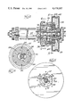
- FIG. 1 is a somewhat schematic vertical section of a burster made according to the invention
- FIG. 2 is a front elevational view of the infeed roller pair with parts shown in section for clarity;
- FIG. 3 is a view of the driven one of the infeed rollers illustrating a limited loss motion connection in section
- FIG. 4 is a sectional view taken approximately along the line 4--4 in FIG. 3;
- FIG. 5 is a sectional view taken approximately along line 5--5 in FIG. 3.
- burster frame generally designated 10
- a suitable paper guide 20 defines a path of stationery travel extending from an infeed end 22 of the burster to an outfeed end 24.
- the rollers 12-18 are, of course, located about the path of stationery travel defined by the paper guide 20.
- the spacing between the infeed rollers 12 and 14 and the outfeed rollers 16 and 18 is fixed and a motor, shown schematically at 26, is operatively connected by a suitable drive such as a timing belt to at least one roller in each of the pairs.
- a suitable drive such as a timing belt
- the rollers 14 and 18 may be driven by the motor 26 and the rollers 12 and 16 geared respectively to the rollers 14 and 18 to be driven thereby.
- FIG. 2 Such an arrangement is shown, for example, in FIG. 2 wherein a side member 30 of the frame 10 mounts bearings 32 and 34 which respectively journal shafts 36 and 38 extending from one end of each of the rollers 12 and 14.
- Spur gears 40 and 42 are respectively mounted on the shafts 36 and 38 to be enmeshed with each other so that upon rotation of the lower roller 14 by the motor 26, such rotation would be imparted to the roller 12 by the gears 40 and 42.
- a similar gearing arrangement (not shown) interconnects with the rollers 16 and 18.
- the drive is such that rollers 16 and 18 of the outfeed pair have a higher peripheral velocity than the rollers 12 and 14 of the infeed pair.
- the ratio is 3:2, although other ratios can be used as desired.
- a limited lost motion connection mechanism is connected to the drive shaft 38 for the lower infeed roller 14. This connection is made on the side of an upright frame member 52 opposite from the roller 14 itself and the mechanism 50 includes an external gear-like formation 54 about which a timing belt may be trained to connect the same to the drive motor 26.
- the shaft 38 receives an elongated sleeve 56 which is pinned as by pins 58 to the shaft 38 for rotation therewith.
- the sleeve 56 further includes a radially outwardly directed tooth 60 having parallel sides 62 which act as contact faces for purposes to be seen.
- the sides 62 are planar and it will be appreciated that the plane of each such side diverges from the radial extending from the axis of the shaft 38 on which the tooth 60 is located as the axis of the shaft 38 is approached.
- sleeve 56 and tooth 60 will be made of a metallic material such as steel for strength.
- the spacing between opposed faces 62 that is, the width of the tooth 60, is chosen to achieve a desired life in the mechanism.
- the tooth 60 is continually impacting against stops yet to be described. Such impacting ultimately may cause fatigue such that the tooth 60 fractures and separates from the remainder of the sleeve 56.
- the thicker the tooth the longer it may withstand such impacting so the thickness is chosen to enable the burster to undergo a commercially acceptable number of impact cycles before failure.
- the mechanism 50 further includes first and second stop members 66 and 68 respectively.
- the stop member 66 is seen to include a central aperture 70. Extending into the aperture 70, generally radially thereof, is an integrally formed stop 72.
- the stop 72 has opposed stop faces or surfaces 74 and 76 which, in the exemplary embodiment, are both planar. The same are configured to be substantially parallel to the corresponding contact face 62 of the tooth 60 when in abutment therewith as shown, for example, in FIG. 4.
- the stop faces 74 and 76 are nonradial with respect to the axis of the shaft 38 and moreover converge on the radial on which the stop 72 is located as the axis of the shaft 38 is approached.
- FIG. 5 illustrates a stop 82 similar to the stop 72 carried by the stop member 66.
- the stop 82 has opposed stop faces 84 and 86 and the same are configured identically with respect to the tooth 60 as faces 74 and 76 to achieve the same advantages.
- the stop 82 is integrally formed on the stop member 68 and preferably both the stop member 66 and the stop member 68 are molded of impact resistant plastic. The use of plastic is preferred over metal for this component as it results in a reduced noise level during machine operation from that which would occur if both the tooth 60 and the stops 72 and 82 were of metal. Polyurethane is a preferred plastic because of its availability and price.
- the first stop member 66 carries the gear-like formation 54 about its periphery and, within the body of the stop member 66, to one side of the aperture 70, there is a stepped bore 90 receiving a bearing 92 by which the first stop member 66 is journaled on the shaft 38.
- a snap retainer 94 received in a groove 96 in the shaft 38 serves to limit axial motion of the loss motion mechanism 50 to the left on the shaft 38 as seen in FIG. 3 and such fastener 94 sandwiches the bearing 92 against the sleeve 56 to prevent rightward movement of the mechanism 50 on the shaft 38 as will be seen.
- the left-hand side of the first stop member 66 includes an annular recess receiving a cap 98 which is apertured about the shaft 38 and the fastener 94 but which bears against the outer race of the bearing 92 to hold the same in the stepped bore 90.
- the cap 98 is held in place by a series of flathead screws 100 which extend through bores in the first stop member 66 generally parallel to the shaft 38 to be received in threaded bores in the hub 102 of a shallow cup-like index element 104.
- the index element 104 includes a cylindrical, peripheral flange 106 which in turn is provided with an index mark 108 (FIG. 2).
- the hub 102 of the index element 104 includes a central aperture 110 which slidably receives the second stop member 68 thereby mounting the same for both rotation and axial movement relative to the first stop member 66.
- the left-hand edge of the bore 110 terminates in an enlarged, ring gear formation 112 and the left-hand end of the second stop member 68 is provided with a generally identical spur gear formation 114 which can mesh with the ring gear formation 112.
- a compression coil spring 116 is disposed about the shaft 38 within a cavity 118 in the first stop member 66.
- One end of the coil spring 116 bears against a shoulder 120 formed on the first stop member 66 while the opposite end of the spring 116 bears against a similar shoulder 122 on the left-hand edge of the second stop member 68. Consequently, it will be appreciated that the spring 116 biases or urges the spur gear 114 on the second stop member 68 into engagement with the ring gear 112 carried by the first stop member 66 by reason of the mounting of the index element 104 thereon.
- the right-hand end of the second stop member 68 is provided with an elongated handle 128 which may be gripped between the fingers of an operator of the machine for the purpose.
- the second stop member 68 In order to assure continual positive alignment, the second stop member 68, just to the right of the aperture 80, is provided with a reduced diameter bore 130 which in turn receives a sleeve bearing 132 which, in turn, slidably receives the end of the shaft 38.
- a sleeve bearing 132 which, in turn, slidably receives the end of the shaft 38.
- the mechanism 50 is completed by a scale element 140 mounted on the second stop member 68 and carried therewith by a suitable spline (not shown) and lock ring 142.
- the scale 140 has a peripheral, cylindrical flange 144 sized to just fit within the flange 106 on the index element 104 as well as an annular, radially outwardly directed scale flange 146.
- a series of scale indicia are located about the periphery of the flange 146 and are so disposed thereon such that when a given designation is aligned with the index mark 108, the burster is set up to burst forms of the indicated form length.
- Operation of the apparatus is as follows.
- the handle 128 of the mechanism 50 is grasped by the operator and axially shifted to the left as viewed in FIG. 3 until the gears 112 and 114 are unmeshed.
- the handle 128 is rotated to bring the desired scale character on the scale 148 into alignment with the index mark 108 on the index element 104.
- the desired scale character on the scale 148 For example, if it is desired to burst forms having a form length of 11 inches, the designation 11 inches appearing on the scale 148 is aligned with the index mark 108.
- Business forms are then introduced into the nip of the infeed rollers 12 and 14 and the drive 26 energized.
- the stop face 74 of the stop 72 will be in abutment with one of the contact faces 62 of the tooth 60 as illustrated in FIG. 4 with the consequence that the shaft 38 will be driven thereby driving the lower infeed roller 14 as well as the gear 42.
- the gear 40 will be driven by the gear 42 driving the infeed roller 12 to advance the form along the guides 20.
- a burster made according to the invention provides ease of operation by relatively unskilled personnel in that the adjustment process for varying form lengths is easily effected simply by manipulation of the single handle 128.
Landscapes
- Winding Of Webs (AREA)
- Discharge By Other Means (AREA)
- Perforating, Stamping-Out Or Severing By Means Other Than Cutting (AREA)
Abstract
Description
Claims (10)
Priority Applications (4)
| Application Number | Priority Date | Filing Date | Title |
|---|---|---|---|
| US06/466,814 US4479597A (en) | 1983-02-16 | 1983-02-16 | Burster for continuous form stationery |
| CA000437247A CA1216566A (en) | 1983-02-16 | 1983-09-21 | Burster for continuous form stationery |
| EP83305963A EP0116745A3 (en) | 1983-02-16 | 1983-09-30 | Burster for continuous form stationery |
| JP59027980A JPS59158761A (en) | 1983-02-16 | 1984-02-16 | Burster for paper for continuous form |
Applications Claiming Priority (1)
| Application Number | Priority Date | Filing Date | Title |
|---|---|---|---|
| US06/466,814 US4479597A (en) | 1983-02-16 | 1983-02-16 | Burster for continuous form stationery |
Publications (1)
| Publication Number | Publication Date |
|---|---|
| US4479597A true US4479597A (en) | 1984-10-30 |
Family
ID=23853200
Family Applications (1)
| Application Number | Title | Priority Date | Filing Date |
|---|---|---|---|
| US06/466,814 Expired - Lifetime US4479597A (en) | 1983-02-16 | 1983-02-16 | Burster for continuous form stationery |
Country Status (4)
| Country | Link |
|---|---|
| US (1) | US4479597A (en) |
| EP (1) | EP0116745A3 (en) |
| JP (1) | JPS59158761A (en) |
| CA (1) | CA1216566A (en) |
Cited By (6)
| Publication number | Priority date | Publication date | Assignee | Title |
|---|---|---|---|---|
| US5540369A (en) * | 1993-12-07 | 1996-07-30 | Moore Business Forms, Inc. | Detaching linerless labels |
| US5599011A (en) * | 1993-07-26 | 1997-02-04 | Uarco Incorporated | Sheet feeder |
| US5735443A (en) * | 1993-09-08 | 1998-04-07 | Moore Business Forms Inc | Single part burster |
| US5845462A (en) * | 1996-12-10 | 1998-12-08 | Northfield Corporation | Coupon inserter |
| US7032774B2 (en) | 2000-10-06 | 2006-04-25 | Northfield Corporation | Web burster/inserter |
| US20080236995A1 (en) * | 2007-03-26 | 2008-10-02 | Lindquist Rob W | Bursting apparatus and method |
Families Citing this family (1)
| Publication number | Priority date | Publication date | Assignee | Title |
|---|---|---|---|---|
| DE3500547A1 (en) * | 1985-01-10 | 1986-07-10 | Focke & Co (GmbH & Co), 2810 Verden | METHOD AND DEVICE FOR PRODUCING CUT-OUTS FOR PACKAGING |
Citations (6)
| Publication number | Priority date | Publication date | Assignee | Title |
|---|---|---|---|---|
| US3161335A (en) * | 1962-07-19 | 1964-12-15 | Uarco Inc | Burster |
| US3331543A (en) * | 1965-05-24 | 1967-07-18 | Pratt Mfg Corp | Devices for feeding lengths of breakable material |
| US3338487A (en) * | 1965-10-21 | 1967-08-29 | Varco Inc | Continuous form stationery burster |
| US3493156A (en) * | 1967-06-12 | 1970-02-03 | Uarco Inc | Adjustable outfeed assembly for stationery burster |
| US3672551A (en) * | 1970-11-04 | 1972-06-27 | Uarco Inc | Burster with interrupted drive |
| US4284221A (en) * | 1978-11-30 | 1981-08-18 | Agfa-Gevaert Aktiengesellschaft | Apparatus for breaking weakened portions of running webs or the like |
Family Cites Families (3)
| Publication number | Priority date | Publication date | Assignee | Title |
|---|---|---|---|---|
| GB721727A (en) * | 1951-11-06 | 1955-01-12 | Lanova Corp | Improvements in or relating to means for varying the angular relation between driving and driven shafts |
| FR2247099A5 (en) * | 1973-10-04 | 1975-05-02 | Sodern | Automatic tearing device for perforated paper - has inlet and outlet roller pairs, each with drive and press roller |
| CA1153326A (en) * | 1981-01-05 | 1983-09-06 | Morris Pinczewski | Infeed knob normally disengaged from power shaft |
-
1983
- 1983-02-16 US US06/466,814 patent/US4479597A/en not_active Expired - Lifetime
- 1983-09-21 CA CA000437247A patent/CA1216566A/en not_active Expired
- 1983-09-30 EP EP83305963A patent/EP0116745A3/en not_active Ceased
-
1984
- 1984-02-16 JP JP59027980A patent/JPS59158761A/en active Pending
Patent Citations (6)
| Publication number | Priority date | Publication date | Assignee | Title |
|---|---|---|---|---|
| US3161335A (en) * | 1962-07-19 | 1964-12-15 | Uarco Inc | Burster |
| US3331543A (en) * | 1965-05-24 | 1967-07-18 | Pratt Mfg Corp | Devices for feeding lengths of breakable material |
| US3338487A (en) * | 1965-10-21 | 1967-08-29 | Varco Inc | Continuous form stationery burster |
| US3493156A (en) * | 1967-06-12 | 1970-02-03 | Uarco Inc | Adjustable outfeed assembly for stationery burster |
| US3672551A (en) * | 1970-11-04 | 1972-06-27 | Uarco Inc | Burster with interrupted drive |
| US4284221A (en) * | 1978-11-30 | 1981-08-18 | Agfa-Gevaert Aktiengesellschaft | Apparatus for breaking weakened portions of running webs or the like |
Cited By (9)
| Publication number | Priority date | Publication date | Assignee | Title |
|---|---|---|---|---|
| US5599011A (en) * | 1993-07-26 | 1997-02-04 | Uarco Incorporated | Sheet feeder |
| US5735443A (en) * | 1993-09-08 | 1998-04-07 | Moore Business Forms Inc | Single part burster |
| US5540369A (en) * | 1993-12-07 | 1996-07-30 | Moore Business Forms, Inc. | Detaching linerless labels |
| US5845462A (en) * | 1996-12-10 | 1998-12-08 | Northfield Corporation | Coupon inserter |
| US5966906A (en) * | 1996-12-10 | 1999-10-19 | Northfield Corporation | Coupon inserter |
| US6082079A (en) * | 1996-12-10 | 2000-07-04 | Northfield Corporation | Bursting apparatus |
| US7032774B2 (en) | 2000-10-06 | 2006-04-25 | Northfield Corporation | Web burster/inserter |
| US20080236995A1 (en) * | 2007-03-26 | 2008-10-02 | Lindquist Rob W | Bursting apparatus and method |
| US7540125B2 (en) | 2007-03-26 | 2009-06-02 | Northfield Corporation | Bursting apparatus and method |
Also Published As
| Publication number | Publication date |
|---|---|
| JPS59158761A (en) | 1984-09-08 |
| EP0116745A2 (en) | 1984-08-29 |
| EP0116745A3 (en) | 1985-08-07 |
| CA1216566A (en) | 1987-01-13 |
Similar Documents
| Publication | Publication Date | Title |
|---|---|---|
| US4261497A (en) | Bursting apparatus | |
| US4479597A (en) | Burster for continuous form stationery | |
| US4257147A (en) | Overload clutch for the feed roll of a carding machine | |
| DE68913628T2 (en) | Device for checking properties of sheets of paper or the like. | |
| CH642298A5 (en) | DEVICE FOR SEPARATING PRE-PERFORATED TAPES, PREFERABLY CONTINUOUS BAGS. | |
| DE2245901A1 (en) | DEVICE FOR CONTINUOUSLY TRANSFERRING A TORQUE | |
| EP0432136A2 (en) | Sheet feeding apparatus in a printer | |
| US5641378A (en) | Hand applicator for adhesive sheeting | |
| US3672551A (en) | Burster with interrupted drive | |
| DE60009726T2 (en) | DEVICE FOR PROMOTING FLAT OBJECTS BY MEANS OF A SYNCHRONIZATION SYSTEM | |
| US4222511A (en) | Low noise burster | |
| US3338487A (en) | Continuous form stationery burster | |
| US4212238A (en) | Rotary dog assembly | |
| DE19836235C2 (en) | Device for separating print media | |
| EP1509468B1 (en) | Carrier element | |
| DE10208583B4 (en) | Method of scoring supplied material, roll and scoring means therefor | |
| DE4209262B4 (en) | Apparatus for cutting a strip routinely fed into a product packaging machine | |
| DE1254158B (en) | Device for separating and removing the foremost sheet of a stack of sheets | |
| CN111016293A (en) | Paper conversion equipment and control method | |
| DE10127993A1 (en) | Separating unit for flat components, e.g. letters, consists of a transport supply belt, rollers, retention members, a separating member and a lock unit | |
| DE2903962C3 (en) | Machine for grinding flat surfaces of ferromagnetic workpieces | |
| DE10224839A1 (en) | Drive system for mandrel carrying roll of paper has retainer on inner circumference of roll and carrier elements transmitting torque to roll and engaging with roll in non-positive manner | |
| US4387557A (en) | False twisting apparatus and method | |
| US8230A (en) | V machine foe | |
| SE446839B (en) | DEVICE FOR SUPPLY OF QUITTO AND / OR JOURNAL TAPE |
Legal Events
| Date | Code | Title | Description |
|---|---|---|---|
| AS | Assignment |
Owner name: UARCO INCORPORATED; A CORP OF DE. Free format text: ASSIGNMENT OF ASSIGNORS INTEREST.;ASSIGNORS:JOHNSON, MARLAND R.;NAUHEIMER, DONALD J.;REEL/FRAME:004104/0762 Effective date: 19830202 |
|
| STCF | Information on status: patent grant |
Free format text: PATENTED CASE |
|
| FEPP | Fee payment procedure |
Free format text: PAYOR NUMBER ASSIGNED (ORIGINAL EVENT CODE: ASPN); ENTITY STATUS OF PATENT OWNER: LARGE ENTITY |
|
| FPAY | Fee payment |
Year of fee payment: 4 |
|
| FPAY | Fee payment |
Year of fee payment: 8 |
|
| AS | Assignment |
Owner name: SUMITOMO BANK, LIMITED, NEW YORK BRANCH, AS COLLAT Free format text: SECURITY INTEREST;ASSIGNOR:UARCO INCORPORATED;REEL/FRAME:006934/0885 Effective date: 19940309 |
|
| FPAY | Fee payment |
Year of fee payment: 12 |
|
| AS | Assignment |
Owner name: UARCO INCORPORATED, ILLINOIS Free format text: RELEASE OF ASSIGNMENT FOR SECURITY;ASSIGNOR:SUMITOMO BANK, LIMITED, NEW YORK BRANCH, AS COLLATERAL AGENT, THE;REEL/FRAME:008975/0559 Effective date: 19971231 |
|
| AS | Assignment |
Owner name: STANDARD REGISTER COMPANY, THE, OHIO Free format text: MERGER;ASSIGNOR:UARCO INCORPORATED;REEL/FRAME:009525/0846 Effective date: 19980324 |
|
| AS | Assignment |
Owner name: BANK OF AMERICA, N.A.,GEORGIA Free format text: NOTICE OF GRANT OF SECURITY INTEREST IN PATENTS;ASSIGNOR:THE STANDARD REGISTER COMPANY;REEL/FRAME:024170/0252 Effective date: 20100331 Owner name: BANK OF AMERICA, N.A., GEORGIA Free format text: NOTICE OF GRANT OF SECURITY INTEREST IN PATENTS;ASSIGNOR:THE STANDARD REGISTER COMPANY;REEL/FRAME:024170/0252 Effective date: 20100331 |
|
| AS | Assignment |
Owner name: THE STANDARD REGISTER COMPANY, OHIO Free format text: RELEASE BY SECURED PARTY;ASSIGNOR:BANK OF AMERICA, N.A.;REEL/FRAME:036283/0027 Effective date: 20150731 Owner name: THE STANDARD REGISTER COMPANY, OHIO Free format text: SECURITY INTEREST;ASSIGNOR:BANK OF AMERICA, N.A., AS ADMINISTRATIVE AGENT;REEL/FRAME:036283/0153 Effective date: 20150731 |
|
| AS | Assignment |
Owner name: THE STANDARD REGISTER COMPANY, OHIO Free format text: RELEASE BY SECURED PARTY;ASSIGNOR:BANK OF AMERICA, N.A., AS ADMINISTRATIVE AGENT;REEL/FRAME:036304/0175 Effective date: 20150731 |