US4475963A - Method for postweld heat treatment - Google Patents
Method for postweld heat treatment Download PDFInfo
- Publication number
- US4475963A US4475963A US06/231,913 US23191381A US4475963A US 4475963 A US4475963 A US 4475963A US 23191381 A US23191381 A US 23191381A US 4475963 A US4475963 A US 4475963A
- Authority
- US
- United States
- Prior art keywords
- hydrogen concentration
- hydrogen
- welding
- weld
- heat treatment
- Prior art date
- Legal status (The legal status is an assumption and is not a legal conclusion. Google has not performed a legal analysis and makes no representation as to the accuracy of the status listed.)
- Expired - Lifetime
Links
- 238000010438 heat treatment Methods 0.000 title claims abstract description 37
- 238000000034 method Methods 0.000 title claims abstract description 34
- 229910052739 hydrogen Inorganic materials 0.000 claims abstract description 195
- 239000001257 hydrogen Substances 0.000 claims abstract description 195
- UFHFLCQGNIYNRP-UHFFFAOYSA-N Hydrogen Chemical compound [H][H] UFHFLCQGNIYNRP-UHFFFAOYSA-N 0.000 claims abstract description 131
- 238000003466 welding Methods 0.000 claims abstract description 123
- 150000002431 hydrogen Chemical class 0.000 claims abstract description 63
- 238000005336 cracking Methods 0.000 claims abstract description 35
- 238000009792 diffusion process Methods 0.000 claims abstract description 30
- 239000002184 metal Substances 0.000 claims description 47
- 229910052751 metal Inorganic materials 0.000 claims description 47
- 230000002265 prevention Effects 0.000 claims description 8
- 229910000851 Alloy steel Inorganic materials 0.000 claims description 4
- 238000012360 testing method Methods 0.000 description 34
- 238000010586 diagram Methods 0.000 description 25
- 238000009826 distribution Methods 0.000 description 22
- 239000011324 bead Substances 0.000 description 19
- 229910000831 Steel Inorganic materials 0.000 description 17
- 239000010959 steel Substances 0.000 description 17
- 239000000463 material Substances 0.000 description 14
- 238000004458 analytical method Methods 0.000 description 9
- 239000010953 base metal Substances 0.000 description 7
- 238000000137 annealing Methods 0.000 description 6
- 230000004907 flux Effects 0.000 description 6
- 238000004364 calculation method Methods 0.000 description 5
- 238000005259 measurement Methods 0.000 description 5
- 239000000126 substance Substances 0.000 description 5
- 238000001816 cooling Methods 0.000 description 4
- 239000000203 mixture Substances 0.000 description 4
- 238000011160 research Methods 0.000 description 4
- 101000983970 Conus catus Alpha-conotoxin CIB Proteins 0.000 description 3
- 230000008859 change Effects 0.000 description 3
- 239000007789 gas Substances 0.000 description 3
- 150000002739 metals Chemical class 0.000 description 3
- 230000008569 process Effects 0.000 description 3
- 238000005204 segregation Methods 0.000 description 3
- IJGRMHOSHXDMSA-UHFFFAOYSA-N Atomic nitrogen Chemical compound N#N IJGRMHOSHXDMSA-UHFFFAOYSA-N 0.000 description 2
- 230000007423 decrease Effects 0.000 description 2
- 230000003111 delayed effect Effects 0.000 description 2
- 238000001514 detection method Methods 0.000 description 2
- 238000002474 experimental method Methods 0.000 description 2
- 238000004519 manufacturing process Methods 0.000 description 2
- 230000007246 mechanism Effects 0.000 description 2
- 238000012986 modification Methods 0.000 description 2
- 230000004048 modification Effects 0.000 description 2
- 238000005070 sampling Methods 0.000 description 2
- CURLTUGMZLYLDI-UHFFFAOYSA-N Carbon dioxide Chemical compound O=C=O CURLTUGMZLYLDI-UHFFFAOYSA-N 0.000 description 1
- 229910045601 alloy Inorganic materials 0.000 description 1
- 239000000956 alloy Substances 0.000 description 1
- 238000005275 alloying Methods 0.000 description 1
- 230000004075 alteration Effects 0.000 description 1
- 229910052799 carbon Inorganic materials 0.000 description 1
- 235000011089 carbon dioxide Nutrition 0.000 description 1
- 239000003245 coal Substances 0.000 description 1
- 230000000052 comparative effect Effects 0.000 description 1
- 238000004590 computer program Methods 0.000 description 1
- 230000008602 contraction Effects 0.000 description 1
- 239000002826 coolant Substances 0.000 description 1
- 230000001186 cumulative effect Effects 0.000 description 1
- 230000003247 decreasing effect Effects 0.000 description 1
- 238000013461 design Methods 0.000 description 1
- 230000001066 destructive effect Effects 0.000 description 1
- 230000003009 desulfurizing effect Effects 0.000 description 1
- 230000006866 deterioration Effects 0.000 description 1
- 230000000694 effects Effects 0.000 description 1
- 238000005530 etching Methods 0.000 description 1
- 238000000605 extraction Methods 0.000 description 1
- 125000004435 hydrogen atom Chemical group [H]* 0.000 description 1
- 238000002347 injection Methods 0.000 description 1
- 239000007924 injection Substances 0.000 description 1
- 238000007689 inspection Methods 0.000 description 1
- 230000010354 integration Effects 0.000 description 1
- 239000007788 liquid Substances 0.000 description 1
- 229910052757 nitrogen Inorganic materials 0.000 description 1
- 230000035515 penetration Effects 0.000 description 1
- 230000001902 propagating effect Effects 0.000 description 1
- 238000003908 quality control method Methods 0.000 description 1
- 239000007787 solid Substances 0.000 description 1
- 238000012546 transfer Methods 0.000 description 1
- XLYOFNOQVPJJNP-UHFFFAOYSA-N water Substances O XLYOFNOQVPJJNP-UHFFFAOYSA-N 0.000 description 1
Images


Classifications
-
- C—CHEMISTRY; METALLURGY
- C21—METALLURGY OF IRON
- C21D—MODIFYING THE PHYSICAL STRUCTURE OF FERROUS METALS; GENERAL DEVICES FOR HEAT TREATMENT OF FERROUS OR NON-FERROUS METALS OR ALLOYS; MAKING METAL MALLEABLE, e.g. BY DECARBURISATION OR TEMPERING
- C21D11/00—Process control or regulation for heat treatments
-
- C—CHEMISTRY; METALLURGY
- C21—METALLURGY OF IRON
- C21D—MODIFYING THE PHYSICAL STRUCTURE OF FERROUS METALS; GENERAL DEVICES FOR HEAT TREATMENT OF FERROUS OR NON-FERROUS METALS OR ALLOYS; MAKING METAL MALLEABLE, e.g. BY DECARBURISATION OR TEMPERING
- C21D3/00—Diffusion processes for extraction of non-metals; Furnaces therefor
- C21D3/02—Extraction of non-metals
- C21D3/06—Extraction of hydrogen
-
- C—CHEMISTRY; METALLURGY
- C21—METALLURGY OF IRON
- C21D—MODIFYING THE PHYSICAL STRUCTURE OF FERROUS METALS; GENERAL DEVICES FOR HEAT TREATMENT OF FERROUS OR NON-FERROUS METALS OR ALLOYS; MAKING METAL MALLEABLE, e.g. BY DECARBURISATION OR TEMPERING
- C21D9/00—Heat treatment, e.g. annealing, hardening, quenching or tempering, adapted for particular articles; Furnaces therefor
- C21D9/50—Heat treatment, e.g. annealing, hardening, quenching or tempering, adapted for particular articles; Furnaces therefor for welded joints
Definitions
- the gist of the present invention resides in:
- D i a hydrogen diffusivity coefficient (cm 2 /sec) in an arbitrary weld zone of each unit layer;
- the first step of obtaining the value of [Co] can be realized by various means or procedures in practical applications.
- the gist of the invention resides in the above-mentioned steps (1) to (7) and is not limited to practical procedures employed therefor.
- the particular procedures developed in the following description are given only as typical examples and should not be construed as limiting the present invention.
- the invention includes all modifications and alterations as encompassed by the appended claims.
- FIG. 1(A) is a perspective view showing the conditions of test welding and FIG. 1(B) illustrates a sampling position of a test piece;
- FIG. 2 is a diagrammatic view explanatory of the way to divide a welded joint into small elements for the analysis by the finite element method
- FIG. 3 is a flow chart showing a program for the analysis by the finite element method
- FIG. 4 is a diagram showing the dependency on temperature of various thermal constants
- FIG. 5 is a diagram showing the relation between the hydrogen diffusivity coefficient and the temperature
- FIG. 6 is a schematic view explanatory of the restraint test specimen used in the cracking tests
- FIGS. 7(A) and 7(B) are schematic perspective views showing the method for measuring diffusible hydrogen which is dissolved into weld metal by one welding pass;
- FIG. 8 is a diagram comparatively showing the actually measured and calculated values of the hydrogen concentration distribution at a point in time when the final bead reaches an interpass temperature
- FIGS. 9(A) and (B) are the diagrams showing the relations between the hydrogen concentration immediately beneath the final pass of welds right after welding and the parameter ( ⁇ ) of hydrogen diffusion at the time of welding for weld metal of 21/4Cr--1Mo steel weldments and for HAZ of A508 Class 3 weldments, respectively;
- FIG. 10 is a schematic view of gas burners employed for auxiliary heating for maintaining an interpass temperature at the time of welding;
- FIGS. 11 and 12 are diagrams showing the relation between welding conditions and the parameter ( ⁇ ) of hydrogen diffusion with auxiliary heating for 21/4Cr--1Mo steel weldments;
- FIG. 13 is a diagram showing the same relation for A508 Class 3 weldments as FIGS. 11 and 12.
- FIG. 14(A) is a diagram showing the influence of the hydrogen concentration distribution immediately after welding on the relation between the variation in hydrogen concentration in weld metal and treating conditions of the low temperature PWHT;
- FIG. 14(B) is the same diagram for HAZ as FIG. 14(A);
- FIG. 15(A) is a diagram for weld metal showing the similar influence of the plate thickness
- FIG. 15(B) is the similar diagram for HAZ as FIG. 15(A);
- FIG. 16(A) is a diagram for weld metal showing the similar influence of the beveling width
- FIGS. 18(A) and 18(B) are the diagrams showing the results of cracking tests for 21/4Cr--1Mo steel and A508 Class 3 material along with the distribution of hydrogen concentration, which were conducted for determining the crack-preventing critical hydrogen concentration;
- FIG. 19 is a graph showing the relation between the crack-preventing critical hydrogen concentration in weld metal or in HAZ and maximum Vicker's hardness number of microstructure in the respective region;
- FIG. 20 is a flow chart illustrating procedures for determining the conditions of the crack-preventing low temperature PWHT for various materials.
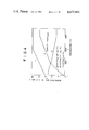
- FIG. 22 is a diagram showing the relation between the lapse of time in the course of measurement at the respective measuring points of the temperatures of the shell course 1 heated by burners 9A and 9B and the hydrogen diffusivity coefficient (D pi ) at the respective temperatures.
- the base metal used in the tests was 200 mm thick rolled material of ASTM A387 GR22 Class 2 and a forged A508 Class 3 material. Those chemical compositions and mechanical properties are shown in Table 1.
- Table 2 below shows the submerged arc welding conditions.
- the flux MF-29A or MF-27 was mainly used in the tests but the recently developed flux MF-29AX of low hydrogen level was used in certain cases.
- Table 3 shows the chemical composition and mechanical properties of the weld metals.
- FIG. 1(A) The shape and dimensions of the welding joint used for the measurement of diffusible hydrogen concentration are shown in FIG. 1(A), while the sampling position of the test piece for its purpose is shown in FIG. 1(B) in which the various lengths are in the unit of mm and indicated by reference number 1 are trays for holding a cooling medium and dry ice and by reference number 2 is a cut of the weld metal test piece.
- the present invention is based on research directed to plates of a thickness of 50 mm or greater which require welding in a relatively large number of layers and the submerged arc welding process is generally utilized with high heat input, so that it is almost impossible to simulate on the test piece the welding thermal cycle which takes place when welding an actual structure. Therefore, an analysis based on the finite element method was utilized.
- FIG. 2 illustrates an element division of a weld zone into small triangless of I-beveling welded with 2 passes per layer and having a penetration rate of 60%.
- reference numeral 6 denotes the weld of the first pass consisting of a weld portion 4 and a penetrated portion 5.
- reference number 6' is the weld of the 12th pass consisting of a weld portion 4' and a penetrated portion 5'.
- the sum of residual hydrogen in the penetrated portion and a predetermined amount of hydrogen dissolved in the respective weld portion at the time of each weld is divided by the total weight of the weld and penetrated portions, allotting the mean value uniformly thereto as initial hydrogen concentration existing when welding each weld pass.
- the hydrogen concentration at the nodes on the surfaces were considered as being constantly held at zero throughout the analysis.
- FIG. 3 is a flow chart of a program used for the analysis.
- the time increment for each analysis was set in the range of 1 to 10 seconds to correspond with the cooling rate.
- the shift to the next pass was affected when a predetermined temperature was reached at a position located 10 mm inside the beveling face and 15 mm deep from the plate surface, compiling that temperature as an interpass temperature. With a larger plate thickness, the temperature was controlled by varying the measuring positions a few times along the plate thickness in accordance with the progress of the welding operation. In the various tests using a test specimen as shown in FIG. 1, the welding thermal cycle was controlled by a CA thermocouple which was inserted at such measuring positions for conformity with conditions of calculation.
- FIGS. 4 and 5 show the dependency on temperature of the various thermal constants and the hydrogen diffusivity coefficient which were used in the calculations.
- the thermal transfer coefficient A thermal conductivity B and specific heat C
- the density was held constant in consideration of their dependency on temperature shown.
- the value indicated by solid lines in FIG. 5 was used.
- the hydrogen diffusivity coefficient was determined by actually measuring the distributions of hydrogen concentration immediately after welding and after the low-temperature PWHT and comparing the measured values with calculated values as obtained under the same conditions.
- the low-temperature PWHT was performed in an annealing furnace. Leaving the test specimen at room temperature for two weeks after the low-temperature PWHT, vertical sections of the weld were cut out to check the existence of cracks by magnaflux detection and by the naked eye after etching.
- the hydrogen diffusion during PWHT was analyzed by the use of the thermal history which was obtained in the cracking test during the time interval from the completion of welding to the time point when the temperature of the test specimen cooled down to 100° C. after the low temperature PWHT, thereby determining the hydrogen distribution in the weld zone at the temperature of 100° C. Thereafter, the crack-preventing critical hydrogen concentration was determined on the basis of the results of the cracking test and the corresponding distribution of hydrogen concentration.
- test piece as shown in FIG. 7(A) (in which all the dimensions are indicated in the unit of mm) was welded with one pass in the arrowed direction which was, immediately after being quenched in a water bath with crushed ice, put in liquid nitrogen to fix hydrogen. Thereafter, four test pieces were cut off as shown in FIG. 7(B) for the determination of hydrogen. These test pieces were sealed in a vacuum container for about 20 days at room temperature and then subjected to determination of diffusible hydrogen by a vacuum extraction apparatus.
- FIG. 8 shows actually measured and calculated values of the hydrogen distribution in the weld metal of 21/4Cr--1Mo steel weldments when the final pass of the weld is cooled down to the interpass temperature.
- the marks "O", " ⁇ ” and “ ⁇ ” represent the actually measured values and the curves indicate the results of analysis.
- Both the actually measured and calculated values have peaks in the vicinity of a point immediately beneath the final layer, showing a higher value with a greater plate thickness.
- the calculated values coincide with the actually measured values indicative of the reliability of the analyzing computer program.
- the hydrogen distribution in such a case can easily be obtained by the use of the analysing program.
- the hydrogen concentration immediately beneath the final bead after its pass of welding it is determined by dissolved hydrogen from the arc column and residual hydrogen in the vicinity of the penetrated portion of the bead. It is easily conceivable that the latter is determined by dissolved hydrogen from the arc column during each pass of welding and residual hydrogen in the vicinity of the penetrated portion and the welding thermal history until that pass. In this instance, it is known that the dissolved hydrogen from the arc column in each pass welding is constant and according to the results of the study in the regard, the thermal history in each pass or welding is considered to be substantially the same. Therefore, the hydrogen concentration immediately beneath the penetrated portion after welding the final bead in multilayer welding can be determined from the mean hydrogen concentration in the weld immediately after welding the initial layer and one welding thermal history in the proximity of the final layer.
- the abscissa represents ⁇ for i .sup. ⁇ Di ⁇ ti while the ordinate represents the hydrogen concentration in weld metal directly beneath the final bead immediately after welding the final pass, non-dimensionally in terms of the mean hydrogen concentration in the weld metal immediately after the initial welding.
- the discussion is based on welding of one layer with one pass. In a case where one layer is welded with n-number of passes, this relation can be generalized by graduating the abscissa on the scale of (1/n) (the same applies hereafter). The results of calculation shown in FIG.
- the value of the parameter ⁇ which is determined by one welding thermal cycle consists of the value of ⁇ shown in FIGS. 9(A), (B) plus the contribution of the auxiliary heating, that is to say, the product D ⁇ ta of the time interval ⁇ ta at which the welding of a next bead is deposited after the bead temperature reaching the interpass temperature and the coefficient D of hydrogen diffusion at the temperature.
- the value of ⁇ ta varies depending upon the welding conditions such as the interpass temperature, welding speed, dimensions of the base metal, for example, the diameter of a vessel when a girth welding to join the shell courses of a pressure vessel is performed.
- FIG. 11 shows the relation between the pass interval and the parameter ⁇ in a case where a joint of infinitely wide plate of 21/4Cr--1Mo steel is welded at an interpass temperature of 200° C. and, when the bead temperature reaches the interpass temperature at the time of welding each pass, it is maintained constantly at the interpass temperature by the auxiliary heating until the commencement of welding of the next pass.
- the broken line indicates the relation between the time in which the bead temperature cools off to the interpass temperature after the welding of the bead and the value of ⁇ as determined by the welding thermal cycle at that time, namely, the value of i .sup. ⁇ Di ⁇ ti of FIG. 9(A).
- the preheating zones on opposite sides of the weld were locally preheated to 200° C. over a width corresponding to the plate thickness of 50 mm or 100 mm.
- the value of ⁇ thus obtained was 0.041 cm 2 with a plate thickness of 50 mm and 0.022 cm 2 with a plate thickness of 100 mm.
- the value of ⁇ resulting from overall preheating was 0.041 cm 2 with a plate thickness of 50 mm and 0.023 cm 2 with a plate thickness of 100 mm, which were substantially the same as the values in the case of local preheating.
- the straight line which extends out of the broken line indicates the relation between the time ⁇ ta in which the welding of the next pass is initiated after the bead temperature reaching the interpass temperature and the increase in ⁇ due to the auxiliary heating, namely, the relation of D ⁇ ta. Therefore, the gradient of the straight line equals the coefficient of hydrogen diffusivity at the interpass temperature. It is clear therefrom that the pass interval imposes a great influence on the parameter ⁇ in consideration of the auxiliary heating.
- FIG. 12 shows their relation in both cases where the interpass temperature is 150° C. and 250° C. Upon comparing this figure with FIG. 11, it is observed that the influence of the auxiliary heating on the parameter ⁇ becomes greater with a higher interpass temperature although its effect is unexpectable at the temperature of 150° C.
- FIG. 14(A) illustrates the relation between the peak value of the hydrogen concentration in weld metal during the low temperature PWHT and the treating conditions.
- the ordinate represents the ratio of the peak value C of the hydrogen concentration in the low temperature PWHT in weld metal to the hydrogen concentration Co immediately beneath the final bead after welding
- the abscissa represents the sum of the value of the parameter ⁇ of hydrogen diffusion during welding and the product D p ⁇ t p of the coefficient of hydrogen diffusivity at the temperature of the PWHT and the holding time.
- FIG. 15(A) shows the influence of the plate thickness on the relation between the peak values in weld metals and the treating conditions.
- no influence of the plate thickness is observed in the initial stage of the low temperature PWHT. This is because the peak value of the hydrogen concentration is located immediately beneath the final bead and the hydrogen diffusion at that position is greatly influenced by the plate surface. Further, as the heat treatment proceeds, the influence of the plate thickness is gradually manifested due to inward shift of the peak position of the hydrogen concentration.
- FIG. 16(A) shows the influence of the beveling width of the weld on the relation between C/Co in weld metal and ( ⁇ +D p ⁇ t p ).
- FIG. 16(B) is for HAZ. It is clear therefrom that the change of the hydrogen concentration is delayed with a larger beveling width since the gradient of hydrogen concentration in a direction perpendicular to the weld line becomes smaller as the beveling width is increased. When considering the hydrogen diffusion in the weld, it is often discussed as a one-dimensional diffusion in the direction of plate thickness, ignoring the diffusion from the weld to the base metal. However, in view of FIGS.
- FIG. 16(A) shows the influence of the beveling width of up to 36 mm
- the beveling width for plates of a thickness of about 300 mm may be taken as about 36 mm at maximum.
- the beveling width is increased with a greater plate thickness and may exceed 36 mm in some cases. Therefore, next considered is the relation between C/Co in weld metal and ( ⁇ +D p ⁇ t p ) in a case where the beveling width is greater than 36 mm.
- FIG. 18(A) shows the results of cracking tests under different conditions of welding and low temperature PWHT along with hydrogen distributions in the respective test conditions. Since prevention of the cold cracking is considered to depend on the cooling rate to the level of 100° C., the critical hydrogen concentration for the prevention of cracking is expressed by values at the time when the test pieces are cooled to 100° C.
- the curves in this figure indicate the hydrogen concentration distributions in the cooled test pieces at 100° C., of which curves of broken lines are of test pieces with a crack and the curves of solid lines are of test pieces without a crack. It will be clear therefrom that the crack-preventing critical hydrogen concentration in the weld in butt welding of 21/4Cr--1Mo steel is about 3.3 cc/100 gr at a peak value.
- FIG. 19 shows the relation between the hydroen concentration and the microstructure in weld zone in terms of maximum Vicker's hardness number with regard to the occurrence of the crack. Therefore, a straight line in the figure shows the relation between the critical hydrogen concentration [CCr] and the maximum Vicker's hardness number in weld zone [Hv], as is represented by an equation:
- the minimum condition of low-temperature PWHT required to prevent the transverse crack induced in multi-layer welds can be determined.
- the value of [Ccr] should be estimated lower to a certain extent than the value obtained from the equation because the factor of safety should be modified depending upon the importance of the structure, accuracy of non-destructive inspection employed for weld zone, and so forth.
- the conditions for preventing cracking through low temperature PWHT depend on factors such as the shape and dimensions of the weld, the hydrogen level of the flux, type of the base metal or its combination with welding materials and the conditions of the welding operation.
- the conditions for a particular operation for 21/4Cr--1Mo steel weldments are determined by the following procedures.
- Co,o represents the mean hydrogen concentration in the weld immediately after welding the first pass and is 4.74 cc/100 g in the case of submerged arc welding using the flux MF-29 A.
- Ccr/Co of the preceding step (3) are plotted on the ordinate of the diagram of FIG. 16(A) or FIG. 17, reading out the necessary treating conditions ( ⁇ +D p ⁇ t p ) on the abscissa according to the given plate thickness and beveling width.
- ⁇ of the step (1) is subtracted from the value of ( ⁇ +D p ⁇ t p ) of the step (4) to obtain the low temperature PWHT conditions D p ⁇ t p suitable for the plate thickness, preheating and interpass temperatures, number of weld passes per layer, pass intervals, maximum Vicker's hardness number in weld zone, and beveling width as specified in the steps (1) through (4).
- the values of D p and t p represent the hydrogen diffusivity coefficient and the holding time at the treating temperature, respectively, so that the holding time for a given treating temperature can be obtained according to the relation between the hydrogen diffusivity coefficient and the temperature.
- the same condition of PWHT required to prevent the occurrence of a cold cracking in other low alloy steel weldments can be evaluated by following the procedure presented in FIG. 20.
- FIG. 21 schematically shows the PWHT in multilayer welding of a circumferential joint of a pressure vessel, wherein a shell course of a vessel 1 which is rotated on turning rollers 7 in the arrowed direction is heated at two positions by burners 9A and 9B while measuring the temperature of the shell course 1 at six different positions T 1 to T 6 .
- burners 9A and 9B There are no restrictions on the numbers of the burners and measuring points or on the measuring positions or method. However, it is preferred to provide the burners and measuring points at as many positions as possible in order to enhance the accuracy of the heat control.
- the dissipation of diffusible hydrogen is improved all the more in a case where the shell course is heated on both the inner and outer sides thereof.
- the diagram of FIG. 22 shows the relation between the lapse of time in the course of measurement at the respective measuring points of the temperatures of the shell course 1 heated by burners 9A and 9B and the hydrogen diffusivity coefficient (D pi ) at the respective temperatures.
- the diagram shows the positions of the burners 9A and 9B relative to the measuring points. It will be seen therefrom that the hydrogen diffusivity coefficient (D pi ) has a pattern of declining from T 1 to T 3 and from T 4 to T 6 .
- the value of D pi which varies with lapses of time is time-integrated until its cumulative value reaches D p ⁇ t p determined in the step (5).
- the LTPWHT is terminated since the concentration of diffusible hydrogen at the peak position is smaller than the critical hydrogen concentration Ccr at that time point.
- the weld line is uniformly heated along the entire length thereof so that the temperatures measured only at one arbitrary point may be used for the control of the PWHT.
Landscapes
- Chemical & Material Sciences (AREA)
- Engineering & Computer Science (AREA)
- Physics & Mathematics (AREA)
- Thermal Sciences (AREA)
- Crystallography & Structural Chemistry (AREA)
- Mechanical Engineering (AREA)
- Materials Engineering (AREA)
- Metallurgy (AREA)
- Organic Chemistry (AREA)
- Heat Treatment Of Articles (AREA)
- Arc Welding In General (AREA)
Priority Applications (2)
| Application Number | Priority Date | Filing Date | Title |
|---|---|---|---|
| US06/231,913 US4475963A (en) | 1981-02-05 | 1981-02-05 | Method for postweld heat treatment |
| JP57018093A JPS57188623A (en) | 1981-02-05 | 1982-02-05 | After-heat treatment for welding |
Applications Claiming Priority (1)
| Application Number | Priority Date | Filing Date | Title |
|---|---|---|---|
| US06/231,913 US4475963A (en) | 1981-02-05 | 1981-02-05 | Method for postweld heat treatment |
Publications (1)
| Publication Number | Publication Date |
|---|---|
| US4475963A true US4475963A (en) | 1984-10-09 |
Family
ID=22871123
Family Applications (1)
| Application Number | Title | Priority Date | Filing Date |
|---|---|---|---|
| US06/231,913 Expired - Lifetime US4475963A (en) | 1981-02-05 | 1981-02-05 | Method for postweld heat treatment |
Country Status (2)
| Country | Link |
|---|---|
| US (1) | US4475963A (OSRAM) |
| JP (1) | JPS57188623A (OSRAM) |
Cited By (10)
| Publication number | Priority date | Publication date | Assignee | Title |
|---|---|---|---|---|
| US5094702A (en) * | 1989-06-19 | 1992-03-10 | U.S. Dept. Of Energy | Menu driven heat treatment control of thin walled bodies |
| US6398102B1 (en) * | 1999-10-05 | 2002-06-04 | Caterpillar Inc. | Method for providing an analytical solution for a thermal history of a welding process |
| US6523416B2 (en) * | 2000-08-31 | 2003-02-25 | Kawasaki Steel Corporation | Method for setting shape and working stress, and working environment of steel member |
| US20040244509A1 (en) * | 2001-01-09 | 2004-12-09 | Alexander Savitski | Non-destructive butt weld inspection method |
| US7082338B1 (en) | 1999-10-20 | 2006-07-25 | Caterpillar Inc. | Method for providing a process model for a material in a manufacturing process |
| US7306951B1 (en) * | 1999-06-08 | 2007-12-11 | Midwest Research Institute | Method and apparatus for determining diffusible hydrogen concentrations |
| US20080257008A1 (en) * | 2005-02-25 | 2008-10-23 | Eiji Tsuru | High Strength Welded Steel Tube Superior in Hydrogen Embrittlement Cracking Resistance of Weld Metal and Method of Production of Same |
| RU2580582C2 (ru) * | 2014-07-29 | 2016-04-10 | Федеральное государственное автономное образовательное учреждение высшего профессионального образования "Национальный исследовательский Томский политехнический университет" | Способ разводороживания сварных швов магистральных газопроводов |
| RU2657676C1 (ru) * | 2017-05-31 | 2018-06-14 | Федеральное государственное автономное образовательное учреждение высшего образования "Национальный исследовательский Томский политехнический университет" | Способ разводороживания сварных швов толстостенных труб магистральных газопроводов |
| CN112094997A (zh) * | 2020-09-15 | 2020-12-18 | 中南大学 | 一种改善低合金超高强钢焊件耐腐蚀性能的方法 |
-
1981
- 1981-02-05 US US06/231,913 patent/US4475963A/en not_active Expired - Lifetime
-
1982
- 1982-02-05 JP JP57018093A patent/JPS57188623A/ja active Granted
Non-Patent Citations (16)
| Title |
|---|
| Eiji Takahashi et al., Prevention of the Transverse Cracks in Heavy Section Butt Weldments of 2 4 1 Cr 1Mo Steel Through Low Temperature Postweld Treatment (Reports 1 3), Apr. 1979, Oct. 1979, Transaction Japan Welding Society, vol. 10, 1979. * |
| Eiji Takahashi et al., Prevention of the Transverse Cracks in Heavy Section Butt Weldments of 241 Cr--1Mo Steel Through Low Temperature Postweld Treatment (Reports 1-3), Apr. 1979, Oct. 1979, Transaction Japan Welding Society, vol. 10, 1979. |
| Metals Technology, vol. 2, Feb. 1975, London, GB, B. Chew: "Diffusion of Hydrogen in Fillet Welds", pp. 66-72, p. 70. |
| Metals Technology, vol. 2, Feb. 1975, London, GB, B. Chew: Diffusion of Hydrogen in Fillet Welds , pp. 66 72, p. 70. * |
| Metals Technology; Feb. 1975; "Diffusion of Hydrogen in Fillet Welds", B. Chew, W. S. Kyte; pp. 66-72. |
| Metals Technology; Feb. 1975; Diffusion of Hydrogen in Fillet Welds , B. Chew, W. S. Kyte; pp. 66 72. * |
| Ohmae et al., Study on the Rationalization of Intermediate Postweld Heat Treatment, Mar. 1975, Mitsubishi Jukogyo Technical Bulletin, vol. 12, No. 2, pp. 46 51. * |
| Ohmae et al., Study on the Rationalization of Intermediate Postweld Heat Treatment, Mar. 1975, Mitsubishi Jukogyo Technical Bulletin, vol. 12, No. 2, pp. 46-51. |
| Stahl und Eisen, vol. 100, No. 1, Jan. 1, 1980, Dusseldorf, DE V. Pilous: "Beitrag zum Schweissen eines warmfesten Cr--Mo--Ni--V--Stahles mit 0,18%C und 1% Cr fur Schmiedestucke im Kraftwerksbau", pp. 9-12. |
| Stahl und Eisen, vol. 100, No. 1, Jan. 1, 1980, Dusseldorf, DE V. Pilous: Beitrag zum Schweissen eines warmfesten Cr Mo Ni V Stahles mit 0,18%C und 1% Cr fur Schmiedestucke im Kraftwerksbau , pp. 9 12. * |
| Stahl und Eisen, vol. 98, No. 22, Nov. 2, 1978, Dusseldorf, DE V. Pilous: "Temperaturfuhrung beim Schweissen eines warmfesten Cr--Mo--Ni--V--Stahles mit 0,18%C und 0,92% Cr in grossen Wanddicken", pp. 1167-1170. |
| Stahl und Eisen, vol. 98, No. 22, Nov. 2, 1978, Dusseldorf, DE V. Pilous: Temperaturfuhrung beim Schweissen eines warmfesten Cr Mo Ni V Stahles mit 0,18%C und 0,92% Cr in grossen Wanddicken , pp. 1167 1170. * |
| Welding Journal, vol. 58, No. 52, Feb. 1979, Miami, US, W. S. Kyte: "Postweld Heat Treatment for Hydrogen Removal", pp. 54s-58s, Whole document. |
| Welding Journal, vol. 58, No. 52, Feb. 1979, Miami, US, W. S. Kyte: Postweld Heat Treatment for Hydrogen Removal , pp. 54s 58s, Whole document. * |
| Welding Journal; Feb. 1979; "Postweld Heat Treatment for Hydrogen Removal", W. S. Kyte, B. Chew; pp. 54-58. |
| Welding Journal; Feb. 1979; Postweld Heat Treatment for Hydrogen Removal , W. S. Kyte, B. Chew; pp. 54 58. * |
Cited By (13)
| Publication number | Priority date | Publication date | Assignee | Title |
|---|---|---|---|---|
| US5094702A (en) * | 1989-06-19 | 1992-03-10 | U.S. Dept. Of Energy | Menu driven heat treatment control of thin walled bodies |
| US7306951B1 (en) * | 1999-06-08 | 2007-12-11 | Midwest Research Institute | Method and apparatus for determining diffusible hydrogen concentrations |
| US6398102B1 (en) * | 1999-10-05 | 2002-06-04 | Caterpillar Inc. | Method for providing an analytical solution for a thermal history of a welding process |
| US7082338B1 (en) | 1999-10-20 | 2006-07-25 | Caterpillar Inc. | Method for providing a process model for a material in a manufacturing process |
| US6523416B2 (en) * | 2000-08-31 | 2003-02-25 | Kawasaki Steel Corporation | Method for setting shape and working stress, and working environment of steel member |
| US20040244509A1 (en) * | 2001-01-09 | 2004-12-09 | Alexander Savitski | Non-destructive butt weld inspection method |
| US6862944B2 (en) * | 2001-01-09 | 2005-03-08 | Edison Welding Institute, Inc. | Non-destructive butt weld inspection method |
| US20080257008A1 (en) * | 2005-02-25 | 2008-10-23 | Eiji Tsuru | High Strength Welded Steel Tube Superior in Hydrogen Embrittlement Cracking Resistance of Weld Metal and Method of Production of Same |
| US8653400B2 (en) * | 2005-02-25 | 2014-02-18 | Nippon Steel & Sumitomo Metal Corporation | High strength welded steel tube superior in hydrogen embrittlement cracking resistance of weld metal and method of production of same |
| RU2580582C2 (ru) * | 2014-07-29 | 2016-04-10 | Федеральное государственное автономное образовательное учреждение высшего профессионального образования "Национальный исследовательский Томский политехнический университет" | Способ разводороживания сварных швов магистральных газопроводов |
| RU2657676C1 (ru) * | 2017-05-31 | 2018-06-14 | Федеральное государственное автономное образовательное учреждение высшего образования "Национальный исследовательский Томский политехнический университет" | Способ разводороживания сварных швов толстостенных труб магистральных газопроводов |
| CN112094997A (zh) * | 2020-09-15 | 2020-12-18 | 中南大学 | 一种改善低合金超高强钢焊件耐腐蚀性能的方法 |
| CN112094997B (zh) * | 2020-09-15 | 2022-02-15 | 中南大学 | 一种改善低合金超高强钢焊件耐腐蚀性能的方法 |
Also Published As
| Publication number | Publication date |
|---|---|
| JPS57188623A (en) | 1982-11-19 |
| JPH0216371B2 (OSRAM) | 1990-04-17 |
Similar Documents
| Publication | Publication Date | Title |
|---|---|---|
| Silwal et al. | Effect of postweld heat treatment on the toughness of heat-affected zone for grade 91 steel | |
| RU2205245C2 (ru) | Сталь с высоким сопротивлением на разрыв и способ ее производства | |
| US4475963A (en) | Method for postweld heat treatment | |
| CN112432862B (zh) | 一种焊接热裂纹敏感性的综合评价方法 | |
| Sridhar et al. | Effect of process parameters on bead geometry, tensile and microstructural properties of double-sided butt submerged arc welding of SS 304 austenitic stainless steel | |
| Pathak et al. | Three-dimensional finite element analysis to predict the different zones of microstructure in submerged arc welding | |
| Schaupp et al. | Influence of heat control on hydrogen distribution in high-strength multi-layer welds with narrow groove | |
| Lee | Weld metal hydrogen-assisted cracking in thick steel plate weldments | |
| EP0034057B1 (en) | Method for postweld heat treatment | |
| Pitrun | The effect of welding parameters on levels of diffusible hydrogen in weld metal deposited using gas shielded rutile flux cored wires | |
| Singh et al. | Study on the effect of high-temperature ceramic fiber insulating board to weld grade P-91 steel | |
| Nichols | Reheat cracking in welded structures | |
| KR102608524B1 (ko) | 금속 제품의 열처리 방법 | |
| Padilla-Llano et al. | Qualification of Electroslag Welds made from HPS 485W (70W) and 345W (50W) Steels | |
| Totten et al. | Quenchants and Quenching Technology | |
| Lazor et al. | Effect of microalloying on weld cracking in low carbon steels | |
| Lee et al. | A study on transverse weld cracks in 50 mm thick steel plate with SAW process | |
| Sangsuriyun et al. | Effect of welding current on the mechanical performance and microstructural evolution of GTAW-welded AISI 304 stainless steel butt joints | |
| Laufgang | Postweld Heat Treatment | |
| Werner et al. | Investigation of the toughness behavior in cold-formed and welded high-strength steels using fracture mechanics concepts and notch impact test | |
| García-García et al. | Microstructural and Mechanical Characterization of Autogenous GTAW Weld in High-Manganese Austenitic Steel Ti-Containing with Thermal Analysis | |
| Dani | The effect of preheat on the structure and properties of the HAZ of a welded quenched and tempered steel plate | |
| Gedeon | Resistance spot welding of galvanized steel sheet | |
| Takahashi et al. | Heat Treatment (PWHT) by Utilizing Low-Temperature PWHT for Welds | |
| Tsaryuk et al. | TECHNOLOGICAL STRENGTH Of 25Khn3Mfa steel jOInts In suBMergeD arc welDIng |
Legal Events
| Date | Code | Title | Description |
|---|---|---|---|
| AS | Assignment |
Owner name: KABUSHIKI KAISHA KOBE SEIKO SHO, WAKINOHAMA-CHO 1- Free format text: ASSIGNMENT OF ASSIGNORS INTEREST.;ASSIGNORS:TAKAHASHI, EIJI;IWAI, KENJI;REEL/FRAME:004194/0540 Effective date: 19810130 |
|
| STCF | Information on status: patent grant |
Free format text: PATENTED CASE |
|
| FEPP | Fee payment procedure |
Free format text: PAYOR NUMBER ASSIGNED (ORIGINAL EVENT CODE: ASPN); ENTITY STATUS OF PATENT OWNER: LARGE ENTITY |
|
| FPAY | Fee payment |
Year of fee payment: 4 |
|
| FPAY | Fee payment |
Year of fee payment: 8 |
|
| FPAY | Fee payment |
Year of fee payment: 12 |