US4470880A - Method for separating a liquid waste finish composition - Google Patents
Method for separating a liquid waste finish composition Download PDFInfo
- Publication number
- US4470880A US4470880A US06/389,839 US38983982A US4470880A US 4470880 A US4470880 A US 4470880A US 38983982 A US38983982 A US 38983982A US 4470880 A US4470880 A US 4470880A
- Authority
- US
- United States
- Prior art keywords
- vessel
- composition
- aqueous
- water vapor
- finish composition
- Prior art date
- Legal status (The legal status is an assumption and is not a legal conclusion. Google has not performed a legal analysis and makes no representation as to the accuracy of the status listed.)
- Expired - Lifetime
Links
Images

Classifications
-
- B—PERFORMING OPERATIONS; TRANSPORTING
- B01—PHYSICAL OR CHEMICAL PROCESSES OR APPARATUS IN GENERAL
- B01D—SEPARATION
- B01D1/00—Evaporating
- B01D1/22—Evaporating by bringing a thin layer of the liquid into contact with a heated surface
- B01D1/222—In rotating vessels; vessels with movable parts
- B01D1/228—In rotating vessels; vessels with movable parts horizontally placed cylindrical container or drum
-
- B—PERFORMING OPERATIONS; TRANSPORTING
- B01—PHYSICAL OR CHEMICAL PROCESSES OR APPARATUS IN GENERAL
- B01D—SEPARATION
- B01D3/00—Distillation or related exchange processes in which liquids are contacted with gaseous media, e.g. stripping
- B01D3/10—Vacuum distillation
-
- Y—GENERAL TAGGING OF NEW TECHNOLOGICAL DEVELOPMENTS; GENERAL TAGGING OF CROSS-SECTIONAL TECHNOLOGIES SPANNING OVER SEVERAL SECTIONS OF THE IPC; TECHNICAL SUBJECTS COVERED BY FORMER USPC CROSS-REFERENCE ART COLLECTIONS [XRACs] AND DIGESTS
- Y10—TECHNICAL SUBJECTS COVERED BY FORMER USPC
- Y10S—TECHNICAL SUBJECTS COVERED BY FORMER USPC CROSS-REFERENCE ART COLLECTIONS [XRACs] AND DIGESTS
- Y10S203/00—Distillation: processes, separatory
- Y10S203/13—Spirits
Definitions
- the present invention relates to the separation of a liquid mixture into its aqueous and non-aqueous liquid phases. More particularly, the invention is related to the separation of the aqueous and non-aqueous phases of a finish composition diluted with water and having a Brookfield viscosity at 25° C. of 2 to 115 centipoise.
- multifilament synthetic polymer yarn especially polyester and polyamide yarns
- a spin finish or overfinish composition to improve processing of the yarn and ultimate yarn properties.
- finish compositions may be applied to the yarn in a variety of ways, for example by contact with a roll rotating in a trough of the composition or with a surface to which the composition is metered.
- the waste finish composition is diluted with distilled or deionized water for removal from the process equipment and then fed to a collection point for disposal. There may be components of the non-aqueous phase of the waste finish composition which require disposal of the composition in a hazardous waste disposal facility approved by the Environmental Protection Agency.
- the water content of the waste finish composition may be quite high, for example as high as 99 percent, it is desirable to develop a method to separate the aqueous and non-aqueous phases for disposal of the non-aqueous phase; transportation and disposal costs necessary for ultimate disposal of the waste would accordingly be greatly decreased.
- FIG. 1 of British Patent Specification No. 1,019,099 to Snia Viscosa hereby incorporated by reference, describes apparatus (a rotary dryer) similar to that used in practicing the method of the present invention.
- the present invention provides a method for separating a liquid mixture into its aqueous and non-aqueous liquid phases.
- the method comprises the steps of introducing the liquid mixture into a gas-tight vessel, preferably via a spray nozzle which discharges jets of the liquid mixture onto the inside surface of the vessel; rotating the vessel at a surface speed of approximately 19 to 190 ft/min (0.095 to 0.950 m/s) to cause filming of the liquid composition, while simultaneously heating the vessel, preferably to a temperature of about 90° to 92° C., to cause the aqueous phase to evaporate; removing the water vapor under vacuum, preferably under vacuum of 203 to 508 torr; and condensing the water vapor for removal.
- the liquid mixture be a finish composition diluted with water and having a viscosity of 2 to 115 centipoise (cps). It is also preferred that the liquid mixture be filtered with a 40 to 100, preferably the latter, micron filter prior to being introduced into the vessel.
- the present invention provides a method for separating the aqueous and non-aqueous phases of a finish composition diluted with water and having a viscosity of 2 to 115 cps.
- the method comprises the steps of filtering the diluted finish composition with a 40 to 100 micron filter; injecting the diluted finish composition into a gas-tight vessel via a spray nozzle which discharges jets of the composition onto the inside surface of the vessel; rotating the vessel at a surface speed of approximately 19 to 190 ft/min (0.095 to 0.950 m/s) to cause filming of the composition, while simultaneously heating the vessel to a temperature of about 90° to 92° C. to cause the aqueous phase to evaporate; removing the water vapor under vacuum of 203 to 508 torr; and condensing the water vapor for removal.
- FIG. 1 is a schematic view of apparatus for practicing the present invention.
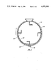
- FIG. 2 is a cross-section taken on lines 2--2 of FIG. 1.
- a gas-tight vessel 10 is held eccentrically at two diametrically opposed ends by tires 13 that run on trunnion rolls (unshown) and are driven for rotation of vessel 10 by conventional motor 14.
- Vessel 10 is preferably about 6 ft (1.8 m) in diameter and 8 ft (2.4 m) in length, and is rotated at a speed of 1 to 10 revolutions per minute, perferably 3 revolutions per minute, to give a surface speed of about 19 to 190 ft/min (0.095 to 0.950 m/s).
- Steam inlet 15 and steam condensate outlet 16 connect through a rotary steam joint to the volume between vessel 10 and jacket 11.
- dimpled jacket flights 20 are connected in a conventional manner with the volume between vessel 10 and jacket 11. In this manner, vessel 10 and angled flights 20 are heated. It is preferred that a sufficient amount of heat be supplied to bring vessel 10 to a temperature of about 90° to 92° C.
- heat traced feed line 17 feeds water diluted finish composition having a Brookfield viscosity at 25° C. of about 2.8 to 2.9 cps through a conventional bag filter 18 having a mesh size, preferably, of 40 to 100 microns.
- the composition is then pumped continuously by a Milton Roy Diaphragm metering pump (not shown) at a flow rate of up to 2.5 gal/min (0.0002 m 3 /s) through a pipe connection in a rotary joint to injection nozzle 19, which discharges jets of the composition onto the heated inner surface of vessel 10 and angled flights 20 attached thereto (see FIG. 2).
- Heated flights 20 function in conjunction with the rotation of vessel 10 to cause filming of the composition for more rapid evaporation of the aqueous phase.
- numeral 21 represents a film of the composition
- numeral 22 represents the accumulating pool of the composition, which with time becomes concentrated with the non-aqueous phase.
- the water vapors are removed from vessel 10 by a vacuum generating device 24 at the end of the process.
- Vacuum generating device 24 may be a conventional vacuum jet or vacuum pump, preferably the latter, under pressure of 203 to 508 torr, most preferably 304 torr.
- the water vapors are removed through the introductory rotary joint through condenser system 23, which comprises two conventional condensers cooled by chilled water and operating in parallel with a condensing capacity of approximately 2.4 gal/min (0.0002 m 3 /s).
- the remaining vapors are combined and moved through a third condenser where an additional condensate flow of approximately 0.1 gal/min (0.0000003 m 3 /s) combines with the flow from the first two condensers.
- Vacuum generating device 24 draws all remaining vapors from the third condenser and exhausts them through a scrubber designed to remove vacuum pump oil vapors from the remaining water vapors. These remaining water vapors are exhausted to the atmosphere. The minute amounts of vacuum pump oil carryover that are removed by the scrubber are returned to a contaminated drain.
- the concentrated non-aqueous phase of the composition that collects as pool 22 in vessel 10 is periodically removed by stopping rotation of vessel 10, connecting a flexible hose to drain 12, opening a valve (unshown) to complete a flow path from vessel 10 through the hose into a receiver tank (unshown) with a vent to the atmosphere.
- This arrangement allows relief of the vacuum on vessel 10 (a valve in the vapor line to the condensers is closed prior to connecting the drain hose).
- the concentrated non-aqueous phase may be stored for subsequent removal and shipping according to established procedures. At the time of discharge from vessel 10, the concentrated non-aqueous phase has a Brookfield viscosity at 25° C. of approximately 115 cps.
- feed of the diluted finish composition to rotating heated vessel 10 continue uninterrupted for twenty-three hours, followed by a one hour period without feed.
- Rotation of the vessel 10 is stopped and the concentrated non-aqueous phase is removed via drain 12. Thereafter, the equipment may be restarted.
Landscapes
- Chemical & Material Sciences (AREA)
- Chemical Kinetics & Catalysis (AREA)
- Vaporization, Distillation, Condensation, Sublimation, And Cold Traps (AREA)
Abstract
Description
Claims (6)
Priority Applications (1)
| Application Number | Priority Date | Filing Date | Title |
|---|---|---|---|
| US06/389,839 US4470880A (en) | 1982-06-18 | 1982-06-18 | Method for separating a liquid waste finish composition |
Applications Claiming Priority (1)
| Application Number | Priority Date | Filing Date | Title |
|---|---|---|---|
| US06/389,839 US4470880A (en) | 1982-06-18 | 1982-06-18 | Method for separating a liquid waste finish composition |
Publications (1)
| Publication Number | Publication Date |
|---|---|
| US4470880A true US4470880A (en) | 1984-09-11 |
Family
ID=23539940
Family Applications (1)
| Application Number | Title | Priority Date | Filing Date |
|---|---|---|---|
| US06/389,839 Expired - Lifetime US4470880A (en) | 1982-06-18 | 1982-06-18 | Method for separating a liquid waste finish composition |
Country Status (1)
| Country | Link |
|---|---|
| US (1) | US4470880A (en) |
Cited By (1)
| Publication number | Priority date | Publication date | Assignee | Title |
|---|---|---|---|---|
| US20030108473A1 (en) * | 2000-12-27 | 2003-06-12 | Ashland Inc. | Process for producing ammonia with ultra-low metals content |
Citations (5)
| Publication number | Priority date | Publication date | Assignee | Title |
|---|---|---|---|---|
| US2623298A (en) * | 1947-01-15 | 1952-12-30 | Fladmark Morten | Process for the utilization of glue water from herring oil and fish meal factories, whale stations, and the like |
| GB1019099A (en) * | 1963-03-15 | 1966-02-02 | Snia Viscosa | Improvements in or relating to the melt-spinning of polyamides |
| US3296709A (en) * | 1962-08-03 | 1967-01-10 | Haas Vakuum Technik G M B H | Rotary drier |
| US3787481A (en) * | 1968-04-11 | 1974-01-22 | Snia Viscosa | Method for the continuous performance of esterification under thermal conditions |
| US3870475A (en) * | 1969-04-07 | 1975-03-11 | Snia Viscosa | Apparatus for the continuous performance of chemical processes, more particulary esterification, and/or transesterification and polycondensation processes |
-
1982
- 1982-06-18 US US06/389,839 patent/US4470880A/en not_active Expired - Lifetime
Patent Citations (5)
| Publication number | Priority date | Publication date | Assignee | Title |
|---|---|---|---|---|
| US2623298A (en) * | 1947-01-15 | 1952-12-30 | Fladmark Morten | Process for the utilization of glue water from herring oil and fish meal factories, whale stations, and the like |
| US3296709A (en) * | 1962-08-03 | 1967-01-10 | Haas Vakuum Technik G M B H | Rotary drier |
| GB1019099A (en) * | 1963-03-15 | 1966-02-02 | Snia Viscosa | Improvements in or relating to the melt-spinning of polyamides |
| US3787481A (en) * | 1968-04-11 | 1974-01-22 | Snia Viscosa | Method for the continuous performance of esterification under thermal conditions |
| US3870475A (en) * | 1969-04-07 | 1975-03-11 | Snia Viscosa | Apparatus for the continuous performance of chemical processes, more particulary esterification, and/or transesterification and polycondensation processes |
Cited By (1)
| Publication number | Priority date | Publication date | Assignee | Title |
|---|---|---|---|---|
| US20030108473A1 (en) * | 2000-12-27 | 2003-06-12 | Ashland Inc. | Process for producing ammonia with ultra-low metals content |
Similar Documents
| Publication | Publication Date | Title |
|---|---|---|
| US3725209A (en) | Centrifugal distillation system | |
| JP3328779B2 (en) | Apparatus and method for treating an emulsion | |
| US2355057A (en) | Apparatus for deaerating viscose compositions | |
| WO1993017770A1 (en) | A solvent recovery and reclamation system | |
| US3249438A (en) | Combination filter and separator unit | |
| US3717554A (en) | Device for reclaiming sweet water from sea water or brackish water | |
| US3200050A (en) | Thermal compression stills | |
| US4470880A (en) | Method for separating a liquid waste finish composition | |
| US6120651A (en) | Method for removing water from an aqueous fluid mixture | |
| US4376680A (en) | Process for demonomerizing polycapronamide | |
| US3622466A (en) | Method of recovering water-free fatty acid distillates by selective condensation | |
| US7610780B2 (en) | Fabric articles dry cleaning machine by solvent nebulization | |
| GB757085A (en) | Improvements in or relating to compression stills and method of continuous distillation | |
| US3893894A (en) | Low temperature water purification system | |
| JP2000282273A (en) | Treatment of waste hydrochloric acid | |
| US6146493A (en) | Method for the concentration of liquid mixtures | |
| US2142726A (en) | Method of filtering and purifying liquids | |
| CN109626690A (en) | T-type distillation machine separation system | |
| US4504355A (en) | Concentrator system | |
| US3521691A (en) | Multistaged moving film and wiped film evaporators | |
| JP2010105257A (en) | Method of recovering additive and apparatus for the same | |
| JPH0780240A (en) | Organic solvent recovering method and apparatus | |
| US3474850A (en) | Liquid film evaporator | |
| US549001A (en) | Art of and apparatus for condensing and evaporating | |
| US2328399A (en) | Coating material recovery medium and process |
Legal Events
| Date | Code | Title | Description |
|---|---|---|---|
| AS | Assignment |
Owner name: ALLIED CORPORATION, COLUMBIA RD. & PARK AVENUE, MO Free format text: ASSIGNMENT OF ASSIGNORS INTEREST.;ASSIGNOR:WARD, CHARLES S.;REEL/FRAME:004018/0092 Effective date: 19820616 Owner name: ALLIED CORPORATION, A CORP. OF N.Y., NEW JERSEY Free format text: ASSIGNMENT OF ASSIGNORS INTEREST;ASSIGNOR:WARD, CHARLES S.;REEL/FRAME:004018/0092 Effective date: 19820616 |
|
| STCF | Information on status: patent grant |
Free format text: PATENTED CASE |
|
| FEPP | Fee payment procedure |
Free format text: PAYOR NUMBER ASSIGNED (ORIGINAL EVENT CODE: ASPN); ENTITY STATUS OF PATENT OWNER: LARGE ENTITY |
|
| FPAY | Fee payment |
Year of fee payment: 4 |
|
| FPAY | Fee payment |
Year of fee payment: 8 |
|
| FPAY | Fee payment |
Year of fee payment: 12 |