US4470656A - Connector assembly for undercarpet communication cable and power cable - Google Patents
Connector assembly for undercarpet communication cable and power cable Download PDFInfo
- Publication number
- US4470656A US4470656A US06/389,821 US38982182A US4470656A US 4470656 A US4470656 A US 4470656A US 38982182 A US38982182 A US 38982182A US 4470656 A US4470656 A US 4470656A
- Authority
- US
- United States
- Prior art keywords
- cable
- base plate
- compartment
- divider
- plate
- Prior art date
- Legal status (The legal status is an assumption and is not a legal conclusion. Google has not performed a legal analysis and makes no representation as to the accuracy of the status listed.)
- Expired - Lifetime
Links
- 239000004020 conductor Substances 0.000 claims description 10
- 239000002184 metal Substances 0.000 description 4
- 238000009434 installation Methods 0.000 description 1
- 238000012986 modification Methods 0.000 description 1
- 230000004048 modification Effects 0.000 description 1
Images


Classifications
-
- H—ELECTRICITY
- H02—GENERATION; CONVERSION OR DISTRIBUTION OF ELECTRIC POWER
- H02G—INSTALLATION OF ELECTRIC CABLES OR LINES, OR OF COMBINED OPTICAL AND ELECTRIC CABLES OR LINES
- H02G3/00—Installations of electric cables or lines or protective tubing therefor in or on buildings, equivalent structures or vehicles
- H02G3/02—Details
- H02G3/08—Distribution boxes; Connection or junction boxes
- H02G3/18—Distribution boxes; Connection or junction boxes providing line outlets
- H02G3/185—Floor outlets and access cups
Definitions
- a terminal block carries electrical terminals that penetrate conductors of the cable.
- the fixture requires a duplex receptacle, i.e., electrical receptacle connector with two receptacles for respective receipt of an electrical plug of the type provided on the electrical cord of a household appliance or office machine. Insulated wires are installed to connect the terminals of the terminal block with the duplex receptacle.
- a housing is assembled over the terminal block and duplex receptacle.
- the present invention resides in an electrical connector assembly comprising a base plate, a hollow cover cooperating with the base plate to define a connector cavity, a divider plate removably secured to the base plate and cooperating with the cover to divide the connector cavity into separate and distinct compartments, the cover having openings communicating with respective compartments of the connector cavity, outlet jacks mounted in respective openings, bezel plates secured removably to the outlet jacks and covering the respective openings in the cover. Electrical connections of the outlet jacks and respective electrical power conductors are contained in one of the compartments. The divider plate separates these electrical connections from the remainder of the connector cavity. The divider plate thereby protects a workman during installation of outlet jacks to communication cable in another compartment.
- the invention permits both electrical power and communication outlets in a single connector assembly.
- An object of the invention is to provide a single electrical connector assembly that provides electrical outlets for continuous, uncut flat power supplying cable and for communication cable, and for isolating the electrical connections to the respective cables in separate compartments.
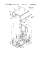
- FIG. 1 is a fragmentary perspective view of an electrical connector assembly according to the present invention installed to a flat undercarpet power cable and a flat communication cable.
- FIG. 2 is an enlarged perspective view with parts exploded of a base plate, divider plate, and cover according to the invention.
- FIG. 3 is an enlarged fragmentary perspective of the electrical connections between outlet receptacles and the respective power and communication cables.
- FIG. 4 is an elevation view in section of the apparatus shown in FIG. 3.
- FIG. 5 is a perspective view of component parts of the outlet receptacles and the connections thereof with the communication cable.
- FIG. 6 is a perspective view with parts exploded of the bezel plate for the communication outlet receptacles.
- FIG. 1 illustrates an electrical connector assembly 1 for mounting on a floor 2 of an office or other commercial space in a building.
- Flat electrical power cable 3 and a flat electrical communication cable 4 are routed across the floor 2.
- the assembly 1 is electrically connected to the conductors of the cables 3 and 4 and provides electrical outlets for those cables.
- a metal shield 5 overlies the power cable 3 to protect the cable from furniture and floor traffic.
- Carpeting 6 overlies the floor 2 and covers the cables 3 and 4 and the shield 5.
- FIGS. 2 and 3 illustrate details of the assembly 1.
- a base plate 7 is stamped and formed from a metal blank and includes a bottom wall 8 having a central opening 9, and side walls 10 on opposite ends of the opening 9 which are bent to project outwardly of the plane of the bottom wall 8.
- the bottom wall 8 includes mounting apertures 11 adjacent the walls 10.
- FIGS. 3 and 4 show that the bottom wall 8 overlies the cable 3 with the cable 3 being continuous, uncut and exposed in the central opening 9.
- the apertures 11 are along opposite sides of the cable 3 and receive threaded apertures 12 that secure in sleeve anchors 13 imbedded in the floor 2.
- a terminal block 14 registers with the opening 9 between the side walls 10 and is electrically connected to the respective conductors of the cable 3. Details of the terminal block 14 and the electrical connections thereof to the cable 3 are disclosed in U.S. Pat. No. 4,240,687.
- FIG. 3 illustrates an electrical terminal 15 of the terminal block 14 at electrically ground potential secured by a bolt type fastener 16 to the metal shield 5.
- a standard duplex receptacle 17 provides a pair of outlet jacks for the power cable 3. Details of the duplex receptacle 17 are disclosed in U.S. Pat. No. 4,240,688. Electrical wires 18, 19, and 20 connect the respective electrical terminals 18', 19', and 20' of the duplex receptacle 17 with respective terminals 15, 18", and 19" of the terminal block 14.
- the duplex receptacle 17 is mounted by threaded fasteners 21 that threadably secure to mounting flanges 22 which are integral with and project from corner posts 23 that, in turn, are integral with and bent to project outwardly of the plane of the bottom wall 8.
- Each corner post 23 is provided with an integral mounting tab 24.
- a cover 25 is stamped and formed from a metal blank into an inverted channel shape with open ends. The cover overlies the base plate 7 to enclose the terminal block 14 and the duplex receptacle 17 and the wires 18, 19, and 20. Side walls 26 of the cover 25 have apertures 24' that receive threaded fasteners 24" that secure in respective tabs 24, so that the cover is secured to the base plate 7.
- the duplex receptacle 17 is exposed at one open end of the cover.
- a bezel plate 27 is removably mounted by threaded fastener 28 to a threaded recess 28' in the duplex receptacle 17.
- the bezel plate 27 fills the open end of the cover 25, covers the respective corner posts 23 and exposes and surrounds the outlet jacks of the duplex receptacle 17.
- Each of the exposed jacks is then available for pluggable connection of an electrical plug of the type provided on the electrical cord of a household appliance or office machine. Power that is conveyed by the conductors of the cable 3 then may be supplied to the appliance or machine.
- the cover 25 and base plate 7 cooperate to define a connector cavity.
- a planar divider plate 29 is shown in FIGS. 2, 3, and 4.
- the divider plate 29 spans across the bottom wall 8 and has edges that are mounted removably in aligned slots 30 of respective slotted tabs 31 which are integral with and are bent to project outwardly from opposite sides of the bottom wall 8 of the base plate 7.
- the divider plate 29 spans across the bottom plate 7 and divides the connector cavity into separate compartments.
- the divider plate thus cooperates with the base plate 7 and the cover 25 to define a compartment that isolates the duplex receptacle 17, the power cable 3 and the electrical connections therebetween.
- FIGS. 5 and 6 illustrate a receptacle electrical connector 32, such as that disclosed in U.S. Pat. No. 3,760,335.
- the connector 32 is electrically connected to the respective conductors of the communication cable 4 in a manner disclosed in U.S. Pat. No. 4,278,314.
- the connector 32 may be connected to the conductors of the cable 4 in a manner disclosed in U.S. Pat. No. 4,147,399.
- a face plate 33 is connected by threaded fasteners 33' to the connector 32.
- a plug 34 in the form of a line assignment module is electrically connected by conductors 35 to a duplex jack 36.
- Each outlet jack 37 of the duplex jack 36 is of standard design approved for use in the U.S.A. National Telephone Network and is disclosed in U.S. Pat. No. 3,850,497.
- Each outlet jack 37, the conductors 35, the line assignment module 34, and the face plate 33 are disclosed in U.S. Pat. No. 4,335,
- FIG. 6 illustrates that the component parts 32, 34, 35, 36, and 37 may be assembled within a compartment defined by cooperation of the base plate 7, the cover 25, and the divider plate 29.
- the duplex jack 36 is assembled with threaded fasteners 36' that threadably secure to the respective mounting flanges 22 of the corner posts 23.
- a bezel plate 38 is secured by threaded fastener 38' that secures in a threaded aperture 38" in the duplex jack 36.
- the bezel plate 38 covers the open end of the compartment and the respective corner posts 23, and surrounds and exposes the outlet jacks 37.
Landscapes
- Engineering & Computer Science (AREA)
- Architecture (AREA)
- Civil Engineering (AREA)
- Structural Engineering (AREA)
- Connector Housings Or Holding Contact Members (AREA)
Abstract
Description
Claims (3)
Priority Applications (1)
| Application Number | Priority Date | Filing Date | Title |
|---|---|---|---|
| US06/389,821 US4470656A (en) | 1982-06-18 | 1982-06-18 | Connector assembly for undercarpet communication cable and power cable |
Applications Claiming Priority (1)
| Application Number | Priority Date | Filing Date | Title |
|---|---|---|---|
| US06/389,821 US4470656A (en) | 1982-06-18 | 1982-06-18 | Connector assembly for undercarpet communication cable and power cable |
Publications (1)
| Publication Number | Publication Date |
|---|---|
| US4470656A true US4470656A (en) | 1984-09-11 |
Family
ID=23539858
Family Applications (1)
| Application Number | Title | Priority Date | Filing Date |
|---|---|---|---|
| US06/389,821 Expired - Lifetime US4470656A (en) | 1982-06-18 | 1982-06-18 | Connector assembly for undercarpet communication cable and power cable |
Country Status (1)
| Country | Link |
|---|---|
| US (1) | US4470656A (en) |
Cited By (17)
| Publication number | Priority date | Publication date | Assignee | Title |
|---|---|---|---|---|
| US4589715A (en) * | 1983-06-06 | 1986-05-20 | Amp Incorporated | Electrical connector kit |
| US4602840A (en) * | 1984-06-01 | 1986-07-29 | Harvey Hubbell Incorporated | Under-carpet connection system |
| US4627684A (en) * | 1984-07-23 | 1986-12-09 | Harvey Hubbell Incorporated | Housing for electrical connectors |
| US4958047A (en) * | 1989-01-13 | 1990-09-18 | Square D Company | Monument fitting |
| GB2236438A (en) * | 1989-09-09 | 1991-04-03 | Baker & Stickland | Floor box for electrical outlets |
| US5025944A (en) * | 1987-06-01 | 1991-06-25 | Rodick Steven F | Outlet assembly for mounting to a wall stud |
| US5243134A (en) * | 1990-05-25 | 1993-09-07 | Westinghouse Electric Corp. | Combination power and communication electrical wall terminal |
| US5243129A (en) * | 1988-08-04 | 1993-09-07 | Amp Incorporated | Flexible undercarpet power system |
| US5288246A (en) * | 1993-04-06 | 1994-02-22 | The Whitaker Corporation | Electrical connector for back panel mounting |
| USD405416S (en) | 1997-07-18 | 1999-02-09 | Byrne Norman R | Shaped power and data unit |
| USD405762S (en) | 1997-10-15 | 1999-02-16 | Fiskars Inc. | Power strip housing |
| USD405763S (en) | 1997-10-15 | 1999-02-16 | Fiskars Inc. | Power strip housing |
| US6042426A (en) * | 1996-11-13 | 2000-03-28 | Byrne; Norman R. | Multi-user electrical services outlet |
| US20040206541A1 (en) * | 2002-06-25 | 2004-10-21 | Lockheed Martin Corporation | Modular interconnectivity system and method |
| US20090264015A1 (en) * | 2008-04-18 | 2009-10-22 | Phoenix Contact Gmbh & Co. Kg | Fastening device for detachable holding of an electrical distributor by latching |
| USD739821S1 (en) | 2014-04-15 | 2015-09-29 | Norman R. Byrne | Power center for a work surface |
| WO2022150698A1 (en) * | 2021-01-11 | 2022-07-14 | Hubbell Incorporated | Back-to-back two-gang electrical box |
Citations (5)
| Publication number | Priority date | Publication date | Assignee | Title |
|---|---|---|---|---|
| FR2098545A5 (en) * | 1970-07-20 | 1972-03-10 | Socapex | |
| US4240688A (en) * | 1979-10-01 | 1980-12-23 | Amp Incorporated | Floor fixture |
| US4289370A (en) * | 1979-05-25 | 1981-09-15 | Thomas & Betts Corporation | Flat conductor cable electrical conductor junction means |
| US4332433A (en) * | 1978-07-28 | 1982-06-01 | Western Electric Co., Inc. | Termination of flat flexible cables |
| US4387949A (en) * | 1981-03-12 | 1983-06-14 | Thomas & Betts Corporation | Transition connection apparatus having grounding feature |
-
1982
- 1982-06-18 US US06/389,821 patent/US4470656A/en not_active Expired - Lifetime
Patent Citations (5)
| Publication number | Priority date | Publication date | Assignee | Title |
|---|---|---|---|---|
| FR2098545A5 (en) * | 1970-07-20 | 1972-03-10 | Socapex | |
| US4332433A (en) * | 1978-07-28 | 1982-06-01 | Western Electric Co., Inc. | Termination of flat flexible cables |
| US4289370A (en) * | 1979-05-25 | 1981-09-15 | Thomas & Betts Corporation | Flat conductor cable electrical conductor junction means |
| US4240688A (en) * | 1979-10-01 | 1980-12-23 | Amp Incorporated | Floor fixture |
| US4387949A (en) * | 1981-03-12 | 1983-06-14 | Thomas & Betts Corporation | Transition connection apparatus having grounding feature |
Cited By (25)
| Publication number | Priority date | Publication date | Assignee | Title |
|---|---|---|---|---|
| US4589715A (en) * | 1983-06-06 | 1986-05-20 | Amp Incorporated | Electrical connector kit |
| US4602840A (en) * | 1984-06-01 | 1986-07-29 | Harvey Hubbell Incorporated | Under-carpet connection system |
| US4627684A (en) * | 1984-07-23 | 1986-12-09 | Harvey Hubbell Incorporated | Housing for electrical connectors |
| US5025944A (en) * | 1987-06-01 | 1991-06-25 | Rodick Steven F | Outlet assembly for mounting to a wall stud |
| US5243129A (en) * | 1988-08-04 | 1993-09-07 | Amp Incorporated | Flexible undercarpet power system |
| US4958047A (en) * | 1989-01-13 | 1990-09-18 | Square D Company | Monument fitting |
| GB2236438A (en) * | 1989-09-09 | 1991-04-03 | Baker & Stickland | Floor box for electrical outlets |
| US5243134A (en) * | 1990-05-25 | 1993-09-07 | Westinghouse Electric Corp. | Combination power and communication electrical wall terminal |
| US5288246A (en) * | 1993-04-06 | 1994-02-22 | The Whitaker Corporation | Electrical connector for back panel mounting |
| US5382180A (en) * | 1993-04-06 | 1995-01-17 | The Whitaker Corporation | Electrical connector for back panel mounting |
| US5397248A (en) * | 1993-04-06 | 1995-03-14 | The Whitaker Corporation | Electrical connector for back panel mounting |
| US6042426A (en) * | 1996-11-13 | 2000-03-28 | Byrne; Norman R. | Multi-user electrical services outlet |
| USD405416S (en) | 1997-07-18 | 1999-02-09 | Byrne Norman R | Shaped power and data unit |
| USD405762S (en) | 1997-10-15 | 1999-02-16 | Fiskars Inc. | Power strip housing |
| USD405763S (en) | 1997-10-15 | 1999-02-16 | Fiskars Inc. | Power strip housing |
| US20040206541A1 (en) * | 2002-06-25 | 2004-10-21 | Lockheed Martin Corporation | Modular interconnectivity system and method |
| US7282645B2 (en) | 2002-06-25 | 2007-10-16 | Lockheed Martin Corporation | Modular interconnectivity system and method |
| US20090264015A1 (en) * | 2008-04-18 | 2009-10-22 | Phoenix Contact Gmbh & Co. Kg | Fastening device for detachable holding of an electrical distributor by latching |
| US8167645B2 (en) * | 2008-04-18 | 2012-05-01 | Phoenix Contact GmbH & Co. LG | Fastening device for detachable holding of an electrical distributor by latching |
| US20120184133A1 (en) * | 2008-04-18 | 2012-07-19 | Phoenix Contact Gmbh & Co. Kg | Fastening device for detachable holding of an electrical distributor by latching |
| US8287307B2 (en) * | 2008-04-18 | 2012-10-16 | Phoenix Contact Gmbh & Co. Kg | Fastening device for detachable holding of an electrical distributor by latching |
| USD739821S1 (en) | 2014-04-15 | 2015-09-29 | Norman R. Byrne | Power center for a work surface |
| WO2022150698A1 (en) * | 2021-01-11 | 2022-07-14 | Hubbell Incorporated | Back-to-back two-gang electrical box |
| US11715941B2 (en) | 2021-01-11 | 2023-08-01 | Hubbell Incorporated | Back-to-back two-gang electrical box |
| US12224568B2 (en) | 2021-01-11 | 2025-02-11 | Hubbell Incorporated | Back-to-back two-gang electrical box |
Similar Documents
| Publication | Publication Date | Title |
|---|---|---|
| US4470656A (en) | Connector assembly for undercarpet communication cable and power cable | |
| US5135411A (en) | Multiple outlet receptacle and mountings therefor | |
| US4978318A (en) | Multiple outlet receptacle and mountings therefor | |
| US5396027A (en) | Strip electrical system | |
| US5106325A (en) | Modular higher density communications coupling system | |
| US4407559A (en) | Connector device with flush mounting receptacle, cover plate and terminal board | |
| US6147304A (en) | Electrical outlet box | |
| US4295697A (en) | Electrical power distribution system principally for space-dividing panels in office buildings | |
| US5007860A (en) | Modular higher density communications coupling system | |
| US6774307B2 (en) | Through-wall electrical system | |
| US5203712A (en) | Circuit wiring device | |
| US6945815B1 (en) | Quick connect electrical outlet | |
| US4403821A (en) | Wiring line tap | |
| US5796037A (en) | Shallow recessed floor box | |
| US4583799A (en) | Multiple outlet receptacle | |
| CA2017589C (en) | Combination power and communication electrical wall terminal | |
| CA2349395C (en) | Feed through box assembly for raceway | |
| US4433204A (en) | Junction box for poke-thru floor fittings | |
| MXPA00003898A (en) | Device bracket. | |
| US4343527A (en) | Telephone connecting device | |
| US4243834A (en) | Cable closure rehabilitation apparatus | |
| US7804026B2 (en) | Enclosure for wiring devices | |
| US1785463A (en) | Duplex receptacle | |
| CA2068250C (en) | Above-floor service fitting for poke-through wiring device | |
| US4502744A (en) | Switching cable assembly |
Legal Events
| Date | Code | Title | Description |
|---|---|---|---|
| AS | Assignment |
Owner name: AMP INCORPORATED, P.O. BIOX 3608, HARRISBURG, PA. Free format text: ASSIGNMENT OF ASSIGNORS INTEREST.;ASSIGNORS:MOSER, JESSIE L.;SIGMON, NED A.;REEL/FRAME:004018/0084 Effective date: 19820528 Owner name: AMP INCORPORATED, PENNSYLVANIA Free format text: ASSIGNMENT OF ASSIGNORS INTEREST;ASSIGNORS:MOSER, JESSIE L.;SIGMON, NED A.;REEL/FRAME:004018/0084 Effective date: 19820528 |
|
| STCF | Information on status: patent grant |
Free format text: PATENTED CASE |
|
| FEPP | Fee payment procedure |
Free format text: PAYOR NUMBER ASSIGNED (ORIGINAL EVENT CODE: ASPN); ENTITY STATUS OF PATENT OWNER: LARGE ENTITY |
|
| FPAY | Fee payment |
Year of fee payment: 4 |
|
| FPAY | Fee payment |
Year of fee payment: 8 |
|
| FEPP | Fee payment procedure |
Free format text: PAYER NUMBER DE-ASSIGNED (ORIGINAL EVENT CODE: RMPN); ENTITY STATUS OF PATENT OWNER: LARGE ENTITY Free format text: PAYOR NUMBER ASSIGNED (ORIGINAL EVENT CODE: ASPN); ENTITY STATUS OF PATENT OWNER: LARGE ENTITY |
|
| FPAY | Fee payment |
Year of fee payment: 12 |