US4456340A - Optical system for focal length conversion - Google Patents
Optical system for focal length conversion Download PDFInfo
- Publication number
- US4456340A US4456340A US06/319,589 US31958981A US4456340A US 4456340 A US4456340 A US 4456340A US 31958981 A US31958981 A US 31958981A US 4456340 A US4456340 A US 4456340A
- Authority
- US
- United States
- Prior art keywords
- lens system
- negative
- positive
- negative lens
- focal length
- Prior art date
- Legal status (The legal status is an assumption and is not a legal conclusion. Google has not performed a legal analysis and makes no representation as to the accuracy of the status listed.)
- Expired - Lifetime
Links
- 230000003287 optical effect Effects 0.000 title claims abstract description 16
- 238000006243 chemical reaction Methods 0.000 title description 9
- 230000005499 meniscus Effects 0.000 claims description 2
- 230000004075 alteration Effects 0.000 description 5
- 238000010586 diagram Methods 0.000 description 4
- 239000011521 glass Substances 0.000 description 3
- 238000001228 spectrum Methods 0.000 description 2
- 230000002159 abnormal effect Effects 0.000 description 1
- 230000007423 decrease Effects 0.000 description 1
- 239000006185 dispersion Substances 0.000 description 1
- 230000000694 effects Effects 0.000 description 1
- 239000005308 flint glass Substances 0.000 description 1
- 229910052746 lanthanum Inorganic materials 0.000 description 1
- FZLIPJUXYLNCLC-UHFFFAOYSA-N lanthanum atom Chemical compound [La] FZLIPJUXYLNCLC-UHFFFAOYSA-N 0.000 description 1
- 238000000926 separation method Methods 0.000 description 1
Images


Classifications
-
- G—PHYSICS
- G02—OPTICS
- G02B—OPTICAL ELEMENTS, SYSTEMS OR APPARATUS
- G02B15/00—Optical objectives with means for varying the magnification
- G02B15/02—Optical objectives with means for varying the magnification by changing, adding, or subtracting a part of the objective, e.g. convertible objective
- G02B15/10—Optical objectives with means for varying the magnification by changing, adding, or subtracting a part of the objective, e.g. convertible objective by adding a part, e.g. close-up attachment
- G02B15/12—Optical objectives with means for varying the magnification by changing, adding, or subtracting a part of the objective, e.g. convertible objective by adding a part, e.g. close-up attachment by adding telescopic attachments
-
- G—PHYSICS
- G02—OPTICS
- G02B—OPTICAL ELEMENTS, SYSTEMS OR APPARATUS
- G02B15/00—Optical objectives with means for varying the magnification
- G02B15/14—Optical objectives with means for varying the magnification by axial movement of one or more lenses or groups of lenses relative to the image plane for continuously varying the equivalent focal length of the objective
- G02B15/142—Optical objectives with means for varying the magnification by axial movement of one or more lenses or groups of lenses relative to the image plane for continuously varying the equivalent focal length of the objective having two groups only
- G02B15/1425—Optical objectives with means for varying the magnification by axial movement of one or more lenses or groups of lenses relative to the image plane for continuously varying the equivalent focal length of the objective having two groups only the first group being negative
Definitions
- This invention relates to optical systems of convertible focal length for increase of the focal length by putting a negative lens system in the rear of a positive lens system.
- FIG. 1 The principle of conversion of the focal length is depicted in FIG. 1. That is, when a negative lens system f' having a negative refractive power is arranged in the rear of a positive lens system f having a positive refractive power, as the distance from the front principal point H to rear principal point H' of the negative lens system, or the principal point interval HH' is generally of positive value, the attachment of the negative lens system f' causes image shift, from a position O for the positive lens system alone, rearwards to a position O'.
- the negative lens system f' in most cases takes the form that the front lens group is divergent and the rear lens group is convergent so that the principal point interval HH' is apt to be positive. For this reason, it has been very difficult to achieve the coincidence of the position of an image point resulting from the attachment of the negative lens system which has found its general use in the conventional focal length-convertible systems to the rear of the positive lens system with that of an image point resulting from the positve lens system only.
- Another object of the present invention is to provide an optical system of convertible focal length which has achieved good stability of aberration correction against the conversion of the focal length.
- FIG. 1 is a schematic diagram for explanation of the principle of focal length conversion of the conventional optical system.
- FIG. 2 is a schematic diagram for explaining the principle of focal length conversion of the present invention.
- FIG. 3 is a lens block diagram of an example of a specific master lens of the present invention.
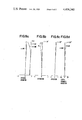
- FIGS. 4 to 7 are lens block diagrams of embodiments 1 to 4 of the present invention respectively.
- FIGS. 8a to 8d are graphic representations of the various aberrations of the master lens of FIG. 3.
- FIGS. 9a to 9d, to 12a to 12d are graphic representations of the various aberrations of the lenses of FIGS. 4 to 7 respectively when attached to the master lens of FIG. 3.
- FIG. 2 The principle of focal length conversion of the present invention is depicted in FIG. 2, where f is the master or positive lens system, and f' is the negative lens system attached to effect focal length conversion. It is seen that the relation of the front and rear principal points H and H' of the negative lens system f' is inverse to that depicted in FIG. 1. In other words, the front principal plane H lies on the image side of the rear principal plane H'. Therefore, the principal plane interval HH' takes a negative value. By adopting such form, it is made possible to cause to coincide the position of an image point for the positive lens system alone with that of an image point O' for the combined system with the negative lens system. We trace a parallel ray of light L incident upon the positive lens system f through the combined lens system.
- the arriving ray at the negative lens system f' will emerge from the rear principal plane H' at the same height from the optical axis as it aims at on the front principal plane, wherein the emerging ray from the negative lens system f' makes a smaller angle with the optical axis than the angle of incidence of the arriving ray on the front principal plane of the negative lens system f', whereby the possibility of bringing the image point O' into coincidence with the image point O can be achieved.
- the negative lens system f' In order that the value of the principal plane interval HH' of the negative lens system f' is negative, as the negative lens system f' is divided into two lens groups, it is required that the front group be of positive power, and the rear group of negative power, and that the following condition be satisfied.
- ⁇ denote the refractive power of the negative lens system f'
- ⁇ 1 the refractive power of the front group
- ⁇ 2 the refractive power of the rear group
- e' the interval between the rear principal point of the front group and the front principal point of the rear group
- the distance, ⁇ 1 of the front principal point of the negative lens system from the front group
- the distance, ⁇ 2, of the rear principal point of the negative lens system from the rear group may be expressed by: ##EQU2## Therefore, in order to make a negative value of the principal point interval of the negative lens system, the satisfaction of ⁇ 1- ⁇ 2>e' suffices.
- the refractive power ⁇ of the negative lens system, the refractive power ⁇ 1 of the front group, the refractive power ⁇ 2 of the rear group and the interval e' between the rear principal point of the front group and the front principal point of the rear group take numerical values listed below:
- the focal length can be increased while maintaining the constant position of the image point.
- the distance from the 1st lens surface to the image plane is 803.45 m/m.
- the distance from the 1st lens surface to the image plane is from 803.41 m/m for Example 1 to be described later, 803.41 m/m for Example 2, 803.40 m/m for Example 3 and 803.43 m/m for Example 4, thus being substantially the same.
- the focal length can be increased by arranging the negative lens system having the aforesaid numerical values of the various factors in rear of the positive lens system, the holding of the image point position unchanged leads to the reduction of the telephoto ratio to an extremely small value.
- the telephoto ratio is about 0.49.
- the Petzval sum is generally increased to a negative direction, and further the secondary spectrum comes to increase.
- the front and rear groups of the negative lens system are each provided with a cemented surface of diverging action to prevent the increase of the Petzval sum. This is achieved by using a glass of low refractive index in the positive lens, and a glass of high refractive index in the negative lens. Also the use of a lanthanum dense flint glass of strong abnormal dispersion in the negative lens well corrects the secondary spectrum.
- the over-correction of spherical aberration resulting from the divergent cemented surface in the front group of the negative lens system is compensated for by constructing the front group from a meniscus doublet lens of forward convexity (in the embodiments, having a negative refractive power) and a bi-convex or positive lens.
- the above lens configuration can achieve an optical system of convertible focal length which is well corrected for aberrations.
- the physical length of the negative lens system lies between at least 1/10 and 1/2 times the back focus of the positive lens system. This is because, unless the physical length of the negative lens system is longer than 1/10 times the back focus of the positive lens system, it becomes difficult to obtain an optical system which preserves the good optical performance. Also because, unless smaller than 1/2 times, it becomes difficult to avoid mechanical interference with the lens mounting, and it will result in the size and bulk of the entire lens system being increased.
Landscapes
- Physics & Mathematics (AREA)
- General Physics & Mathematics (AREA)
- Optics & Photonics (AREA)
- Lenses (AREA)
Abstract
An optical system has a convertible focal length. A positive lens system having a positive refractive power is supplemented by a negative lens system having a negative refractive power between said positive lens system and an image plane to convert the focal length. The front principal point of the aforesaid negative lens system thereby assumes a position rearwardly of the rear principal point thereof, and is made to lie rearwardly of the rear principal point of the aforesaid positive lens system. The overall length of the aforesaid negative lens system is longer than 0.1 times but shorter than 0.5 times the back focus of the aforesaid positive lens system.
Description
1. Field of the Invention
This invention relates to optical systems of convertible focal length for increase of the focal length by putting a negative lens system in the rear of a positive lens system.
2. Description of the Prior Art
Conventionally, in order to convert the focal length, in most cases, it has been the common practice to put what is called the rear attachment lens, or rear conversion lens in the rear of a master lens. The principle of conversion of the focal length is depicted in FIG. 1. That is, when a negative lens system f' having a negative refractive power is arranged in the rear of a positive lens system f having a positive refractive power, as the distance from the front principal point H to rear principal point H' of the negative lens system, or the principal point interval HH' is generally of positive value, the attachment of the negative lens system f' causes image shift, from a position O for the positive lens system alone, rearwards to a position O'. This is because the negative lens system f' in most cases takes the form that the front lens group is divergent and the rear lens group is convergent so that the principal point interval HH' is apt to be positive. For this reason, it has been very difficult to achieve the coincidence of the position of an image point resulting from the attachment of the negative lens system which has found its general use in the conventional focal length-convertible systems to the rear of the positive lens system with that of an image point resulting from the positve lens system only.
It is known to put the negative lens system in an intermediate space of the master lens system in converting the focal length of the entire system as in U.S. Pat. No. 4,240,697. As for the attachment of the negative lens system to the rear of the master lens system in converting the focal length of the entire system, mention is made of U.S. Pat. Nos. 4,129,359 and 4,154,508.
It is an object of the present invention to provide an optical system of convertible focal length in which the focal length is increased by arranging a negative lens system to the rear of a positive lens system, while maintaining the constant position of the image point before and after the addition of the negative lens system.
Another object of the present invention is to provide an optical system of convertible focal length which has achieved good stability of aberration correction against the conversion of the focal length.
FIG. 1 is a schematic diagram for explanation of the principle of focal length conversion of the conventional optical system.
FIG. 2 is a schematic diagram for explaining the principle of focal length conversion of the present invention.
FIG. 3 is a lens block diagram of an example of a specific master lens of the present invention.
FIGS. 4 to 7 are lens block diagrams of embodiments 1 to 4 of the present invention respectively.
FIGS. 8a to 8d are graphic representations of the various aberrations of the master lens of FIG. 3.
FIGS. 9a to 9d, to 12a to 12d are graphic representations of the various aberrations of the lenses of FIGS. 4 to 7 respectively when attached to the master lens of FIG. 3.
The principle of focal length conversion of the present invention is depicted in FIG. 2, where f is the master or positive lens system, and f' is the negative lens system attached to effect focal length conversion. It is seen that the relation of the front and rear principal points H and H' of the negative lens system f' is inverse to that depicted in FIG. 1. In other words, the front principal plane H lies on the image side of the rear principal plane H'. Therefore, the principal plane interval HH' takes a negative value. By adopting such form, it is made possible to cause to coincide the position of an image point for the positive lens system alone with that of an image point O' for the combined system with the negative lens system. We trace a parallel ray of light L incident upon the positive lens system f through the combined lens system. The arriving ray at the negative lens system f' will emerge from the rear principal plane H' at the same height from the optical axis as it aims at on the front principal plane, wherein the emerging ray from the negative lens system f' makes a smaller angle with the optical axis than the angle of incidence of the arriving ray on the front principal plane of the negative lens system f', whereby the possibility of bringing the image point O' into coincidence with the image point O can be achieved.
In order that the value of the principal plane interval HH' of the negative lens system f' is negative, as the negative lens system f' is divided into two lens groups, it is required that the front group be of positive power, and the rear group of negative power, and that the following condition be satisfied. Now letting φ denote the refractive power of the negative lens system f', φ1 the refractive power of the front group, φ2 the refractive power of the rear group, and e' the interval between the rear principal point of the front group and the front principal point of the rear group, and assuming the front and rear groups to be thin lens systems, the distance, Δ1, of the front principal point of the negative lens system from the front group may be expressed by: ##EQU1## and the distance, Δ2, of the rear principal point of the negative lens system from the rear group may be expressed by: ##EQU2## Therefore, in order to make a negative value of the principal point interval of the negative lens system, the satisfaction of Δ1-Δ2>e' suffices.
Therefore, we have e'(φ2+φ1)/φ>e' from this, ##EQU3## That is, what is required is to satisfy the above equation (1)
Next, in the specific embodiments of the present invention to be described later, the refractive power φ of the negative lens system, the refractive power φ1 of the front group, the refractive power φ2 of the rear group and the interval e' between the rear principal point of the front group and the front principal point of the rear group take numerical values listed below:
______________________________________
Example 1  Example 2   Example 3 Example 4
______________________________________
     -0.004901 -0.004529   -0.004732
                                   -0.004683
1     0.005552  0.005774    0.005544
                                    0.005549
2    -0.014194 -0.014076   -0.013895
                                   -0.013838
e'   47.458    46.434      46.986  46.961
______________________________________
When the negative lens system having the above various numerical values of factors is arranged in rear of the positve lens system, the focal length can be increased while maintaining the constant position of the image point. In practical examples, when the positive lens system as the master lens system to be described later exists alone, the distance from the 1st lens surface to the image plane is 803.45 m/m. With the addition of the negative lens system, the distance from the 1st lens surface to the image plane is from 803.41 m/m for Example 1 to be described later, 803.41 m/m for Example 2, 803.40 m/m for Example 3 and 803.43 m/m for Example 4, thus being substantially the same.
On the other hand, though the focal length can be increased by arranging the negative lens system having the aforesaid numerical values of the various factors in rear of the positive lens system, the holding of the image point position unchanged leads to the reduction of the telephoto ratio to an extremely small value. For example, in any of the embodiments to be described later, the telephoto ratio is about 0.49.
As the telephoto ratio decreases, the Petzval sum is generally increased to a negative direction, and further the secondary spectrum comes to increase. On this account, in the embodiments of the invention, the front and rear groups of the negative lens system are each provided with a cemented surface of diverging action to prevent the increase of the Petzval sum. This is achieved by using a glass of low refractive index in the positive lens, and a glass of high refractive index in the negative lens. Also the use of a lanthanum dense flint glass of strong abnormal dispersion in the negative lens well corrects the secondary spectrum. Further, the over-correction of spherical aberration resulting from the divergent cemented surface in the front group of the negative lens system is compensated for by constructing the front group from a meniscus doublet lens of forward convexity (in the embodiments, having a negative refractive power) and a bi-convex or positive lens. The above lens configuration can achieve an optical system of convertible focal length which is well corrected for aberrations.
On the other hand, in order to readily incorporate the negative lens system for focal length conversion in the interior of the mounting for the positive lens system which functions as the master lens, it is preferred from the mechanical standpoint that the physical length of the negative lens system lies between at least 1/10 and 1/2 times the back focus of the positive lens system. This is because, unless the physical length of the negative lens system is longer than 1/10 times the back focus of the positive lens system, it becomes difficult to obtain an optical system which preserves the good optical performance. Also because, unless smaller than 1/2 times, it becomes difficult to avoid mechanical interference with the lens mounting, and it will result in the size and bulk of the entire lens system being increased.
In the following, the specific embodiments of the present invention are shown. The attachment of one of the negative lens systems shown in Example 1 to Example 4 to the master or positive lens system enables the focal length to be increased about 1.41 times without causing a shift of the image point position. In the following tables of the numerical data, Ri is the radius of curvature of the i-th lens surface counting from the front; Di is the i-th lens thickness or air separation counting from the front, and Ni and νi are the refractive index and Abbe number of the glass of the i-th lens element counting from the front respectively.
______________________________________
Master Lens:
F = 1160      FNo. = 1:5.7
                         2ω = 2.137
______________________________________
R1 =  0.0        D1 = 15.00
                           N1 =  1.48749
                                        ν1 = 70.1
R2 =  -602.340   D2 = 1.30
R3 =  940.000    D3 = 25.00
                           N2 =  1.49700
                                        ν2 = 81.6
R4 =  -461.600   D4 = 15.07
R5 =  -410.140   D5 = 11.00
                           N3 =  1.78590
                                        ν3 = 44.2
R6 =  -2259.200  D6 = 6.59
R7 =  302.440    D7 = 22.50
                           N4 =  1.49700
                                        ν4 = 81.6
R8 =  2074.800   D8 = 288.06
R9 =  123.700    D9 = 10.13
                           N5 =  1.51118
                                        ν5 = 51.0
R10 = 539.990   D10 = 3.94
R11 = 311.730   D11 = 4.60 N6 =  1.81600
                                        ν6 = 46.6
R12 = 83.757    D12 = 10.16
                           N7 =  1.50137
                                        ν7 = 56.4
R13 = 225.440   D13 = 17.08
R14 = 236.720   D14 = 3.80 N8 =  1.61340
                                        ν8 = 43.8
R15 = 87.856    D15 = 7.68 N9 =  1.59270
                                        ν9 = 35.3
R16 = 206.420   D16 = 34.20
R17 = 324.130   D17 = 4.83 N10 = 1.74000
                                       ν10 = 28.3
R18 = -2074.800 D18 = 3.50 N11 = 1.71300
                                       ν11 = 53.8
R19 = 139.590
______________________________________
______________________________________
Focal Length Magnification 1.41X
______________________________________
R1    75.621    D1      8.47 N1    1.48749
                                         ν1
                                              70.1
R2    -75.621   D2      2.69 N2    1.883 ν2
                                              40.8
R3    151.077   D3      7.55
R4    198.598   D4      6.08 N3    1.5927
                                         ν3
                                              35.3
R5    -86.991   D5      41.13
R6    -353.091  D6      2.0  N4    1.7725
                                         ν4
                                              49.6
R7    44.061    D7      6.32 N5    1.5927
                                         ν5
                                              35.3
R8    -76.101   D8      1.99
R9    -82.307   D9      2.0  N6    1.7725
                                         ν6
                                              49.6
 R10  59.973    D10     4.0  N7    1.48749
                                         ν7
                                              70.1
 R11  372.075
______________________________________
Focal Length         f = -204.04
Principal Point Interval
                     HH'---- = -25.0
Principal Point Distance
                     E = 1099.08
with Master Lens
Surface interval     D = 102.8
with Master Lens
______________________________________
______________________________________
Focal Length Magnification 1.41X
______________________________________
R1     79.875    D1      8.0  N1   1.48749
                                         ν1
                                              70.1
R2     -73.755   D2      4.0  N2   1.883 ν2
                                              40.8
R3     151.577   D3      5.33
R4     152.661   D4      7.0  N3   1.5927
                                         ν3
                                              35.3
R5     -88.805   D5      39.95
R6     1121.172  D6      4.0  N4   1.5927
                                         ν4
                                              35.3
R7     -579.803  D7      2.5  N5   1.804 ν5
                                              46.6
R8     39.107    D8      1.59
R9     40.541    D9      4.5  N6   1.5927
                                         ν6
                                              35.3
 R10   -127.316  D10     2.0  N7   1.804 ν7
                                              46.6
 R11   120.177
______________________________________
            F = -220.82
            HH'---- = -26.91
            E = 1094.28
            D = 93.07
______________________________________
______________________________________
Focal Length Magnification 1.41X
______________________________________
R1     79.113     D1     8.5  N1   1.48749
                                         ν1
                                              70.1
R2     -77.608    D2     2.95 N2   1.883 ν2
                                              40.8
R3     150.351    D3     6.61
R4     164.209    D4     6.23 N3   1.5927
                                         ν3
                                              35.3
R5     -92.557    D5     41.28
R6     -2002.705  D6     1.71 N4   1.804 ν4
                                              46.6
R7     38.252     D7     7.0  N5   1.5927
                                         ν5
                                              35.3
R8     -79.906    D8     1.0
R9     -86.621    D9     1.7  N6   1.7859
                                         ν6
                                              44.2
 R10   129.063
______________________________________
            f = -211.34
            HH'---- = -25.88
            E = 1096.94
            D = 101.3
______________________________________
______________________________________
Focal Length Magnification 1.41X
______________________________________
R1    77.605     D1     8.52 N1    1.48749
                                         ν1
                                              70.1
R2    -77.605    D2     2.81 N2   1.883  ν2
                                              40.8
R3    139.818    D3     8.06
R4    162.636    D4     6.15 N3   1.5927 ν3
                                              35.3
R5    -89.999    D5     43.94
R6    -1867.407  D6     1.71 N4   1.804  ν4
                                              46.6
R7    38.561     D7     7.0  N5   1.5927 ν5
                                              35.3
R8    -100.778   D8     1.7  N6   1.804  ν6
                                              46.6
R9    143.98
______________________________________
            f = -213.54
            HH'---- = -26.18
            E = 1096.24
            D = 96.95
______________________________________
Claims (5)
1. An optical system of which the focal length is converted by attaching a negative lens system having a negative refractive power to a positive lens system having a positive refractive power in between said positive lens system and an image plane, having the following conditions:
the front principal point of said negative lens system lies on the image side of the rear principal point thereof, and on the image side of the rear principal point of said positive lens system; and
the overall length of said negative lens system being longer than 0.1 times and shorter than 0.5 times the back focus of said positive lens system.
2. An optical system according to claim 1, wherein, when said negative lens system is attached to said positive lens system, the resultant image plane position is almost the same as the image plane position for said positive lens system alone.
3. An optical system according to claim 1, wherein said negative lens system has two lens groups, from front to rear, a positive front group and a negative rear group, and in both the lens groups there is at least one cemented surface of diverging action.
4. An optical system according to claim 3, wherein said front lens group of said negative lens system has, from front to rear, a cemented meniscus lens of forward convexity, and a bi-convex positive lens.
5. In the optical system of claim 4,
said negative lens system consists of two lens groups, or, from front to rear, a positive front group and a negative rear group, satisfying the following condition: ##EQU4## where φ is the refractive power of said negative lens system, and φ1 and φ2 are the refractive powers of said front and said rear groups respectively.
Applications Claiming Priority (2)
| Application Number | Priority Date | Filing Date | Title |
|---|---|---|---|
| JP55-159905 | 1980-11-13 | ||
| JP55159905A JPS5784417A (en) | 1980-11-13 | 1980-11-13 | Optical system for focal length conversion |
Publications (1)
| Publication Number | Publication Date |
|---|---|
| US4456340A true US4456340A (en) | 1984-06-26 |
Family
ID=15703724
Family Applications (1)
| Application Number | Title | Priority Date | Filing Date |
|---|---|---|---|
| US06/319,589 Expired - Lifetime US4456340A (en) | 1980-11-13 | 1981-11-09 | Optical system for focal length conversion |
Country Status (3)
| Country | Link |
|---|---|
| US (1) | US4456340A (en) |
| JP (1) | JPS5784417A (en) |
| DE (1) | DE3145047A1 (en) |
Cited By (2)
| Publication number | Priority date | Publication date | Assignee | Title |
|---|---|---|---|---|
| US20020060853A1 (en) * | 2000-09-28 | 2002-05-23 | Tomoyuki Baba | Wide converter lens |
| US6690518B2 (en) * | 2001-01-10 | 2004-02-10 | Pentax Corporation | Camera-attachment lens system |
Families Citing this family (7)
| Publication number | Priority date | Publication date | Assignee | Title |
|---|---|---|---|---|
| JPS6088916A (en) * | 1983-10-21 | 1985-05-18 | Olympus Optical Co Ltd | Lens system equipped with auxiliary lens |
| CN102129120B (en) | 2010-01-14 | 2012-05-16 | 佛山普立华科技有限公司 | Projection lens |
| JP6291865B2 (en) * | 2014-01-27 | 2018-03-14 | 株式会社リコー | Zoom lens and imaging apparatus using the zoom lens |
| JP7147099B1 (en) * | 2021-03-17 | 2022-10-04 | キヤノン株式会社 | Optical system, lens device, imaging device |
| JP7147097B1 (en) * | 2021-03-17 | 2022-10-04 | キヤノン株式会社 | Optical system, lens device, imaging device |
| JP7146987B1 (en) * | 2021-03-17 | 2022-10-04 | キヤノン株式会社 | Optical system, lens device, imaging device |
| JP7147098B1 (en) * | 2021-03-17 | 2022-10-04 | キヤノン株式会社 | Optical system, lens device, imaging device |
Citations (3)
| Publication number | Priority date | Publication date | Assignee | Title |
|---|---|---|---|---|
| US4239340A (en) * | 1977-10-04 | 1980-12-16 | Minolta Camera Kabushiki Kaisha | Conversion lens system |
| US4253736A (en) * | 1975-11-19 | 1981-03-03 | Canon Kabushiki Kaisha | Combination lens system with attachment lens |
| US4340279A (en) * | 1979-01-11 | 1982-07-20 | Canon Kabushiki Kaisha | Rear attachment lens |
Family Cites Families (8)
| Publication number | Priority date | Publication date | Assignee | Title |
|---|---|---|---|---|
| US4240697A (en) * | 1975-06-05 | 1980-12-23 | Canon Kabushiki Kaisha | Lens system having selectively shiftable focal length |
| JPS52109930A (en) * | 1976-03-11 | 1977-09-14 | Nippon Chemical Ind | Rear conversion lens |
| JPS5323645A (en) * | 1976-08-17 | 1978-03-04 | Canon Inc | Zoom lens capable of easy transfer for focal distance range |
| JPS5834813B2 (en) * | 1976-06-01 | 1983-07-29 | キヤノン株式会社 | attachment lens |
| JPS54135546A (en) * | 1978-04-13 | 1979-10-20 | Canon Inc | Lens system for mounting and dismounting auxiliary lens |
| JPS5515081A (en) * | 1978-07-20 | 1980-02-01 | Tetsuo Kobayashi | Optical fiber dispersion measuring unit |
| JPS5639513A (en) * | 1979-09-10 | 1981-04-15 | Canon Inc | Rear attachment lens |
| JPS5695210A (en) * | 1979-12-28 | 1981-08-01 | Canon Inc | Lens system provided with rear converter lens |
-
1980
- 1980-11-13 JP JP55159905A patent/JPS5784417A/en active Pending
-
1981
- 1981-11-09 US US06/319,589 patent/US4456340A/en not_active Expired - Lifetime
- 1981-11-12 DE DE19813145047 patent/DE3145047A1/en active Granted
Patent Citations (3)
| Publication number | Priority date | Publication date | Assignee | Title |
|---|---|---|---|---|
| US4253736A (en) * | 1975-11-19 | 1981-03-03 | Canon Kabushiki Kaisha | Combination lens system with attachment lens |
| US4239340A (en) * | 1977-10-04 | 1980-12-16 | Minolta Camera Kabushiki Kaisha | Conversion lens system |
| US4340279A (en) * | 1979-01-11 | 1982-07-20 | Canon Kabushiki Kaisha | Rear attachment lens |
Cited By (3)
| Publication number | Priority date | Publication date | Assignee | Title |
|---|---|---|---|---|
| US20020060853A1 (en) * | 2000-09-28 | 2002-05-23 | Tomoyuki Baba | Wide converter lens |
| US6542310B2 (en) * | 2000-09-28 | 2003-04-01 | Fuji Photo Optical Co., Ltd. | Wide converter lens |
| US6690518B2 (en) * | 2001-01-10 | 2004-02-10 | Pentax Corporation | Camera-attachment lens system |
Also Published As
| Publication number | Publication date |
|---|---|
| DE3145047A1 (en) | 1982-06-16 |
| JPS5784417A (en) | 1982-05-26 |
Similar Documents
| Publication | Publication Date | Title |
|---|---|---|
| US5042927A (en) | Compact zoom lens | |
| US5111338A (en) | Zoom Lens | |
| US4260223A (en) | Lens system for photographing objects from infinity to a very short distance | |
| JPH0250117A (en) | Zoom lens | |
| US6487024B2 (en) | Zoom lens system and photographic device equipped therewith | |
| US4634235A (en) | Lens system capable of converting focal length by addition of a lens | |
| US5035492A (en) | Compact and high-speed wide-angle zoom lens system | |
| JPH1020193A (en) | Zoom lens | |
| US5818646A (en) | Zoom lens of rear focus type | |
| US4155629A (en) | Wide angle zoom lens system | |
| US5225937A (en) | Zoom lens | |
| US5585971A (en) | Small-sized variable magnification lens | |
| US4456340A (en) | Optical system for focal length conversion | |
| JP2000275523A (en) | Zoom lens system | |
| US6421186B2 (en) | Zoom lens system | |
| US5229886A (en) | Zoom lens | |
| US5268793A (en) | Zoom lens system | |
| JP3331223B2 (en) | Small two-group zoom lens | |
| US6353507B1 (en) | Zoom lens systems | |
| JP3331011B2 (en) | Small two-group zoom lens | |
| US4364641A (en) | Wide angle zoom lens | |
| JPH01210914A (en) | Variable power lens | |
| US4456341A (en) | Zoom objective | |
| JPH04151116A (en) | Keplerian zoom finder optical system | |
| GB2260423A (en) | Three group zoom lens having at least two aspheric surfaces |
Legal Events
| Date | Code | Title | Description |
|---|---|---|---|
| AS | Assignment |
Owner name: CANON KABUSHIKI KAISHA, NO. 3-30-2, SHIMOMARUKO, O Free format text: ASSIGNMENT OF ASSIGNORS INTEREST.;ASSIGNOR:IKEMORI, KEIJI;REEL/FRAME:003943/0446 Effective date: 19811022 |
|
| STCF | Information on status: patent grant |
Free format text: PATENTED CASE |
|
| FEPP | Fee payment procedure |
Free format text: PAYOR NUMBER ASSIGNED (ORIGINAL EVENT CODE: ASPN); ENTITY STATUS OF PATENT OWNER: LARGE ENTITY |
|
| FPAY | Fee payment |
Year of fee payment: 4 |
|
| FPAY | Fee payment |
Year of fee payment: 8 |
|
| FPAY | Fee payment |
Year of fee payment: 12 |