US4456202A - Burst height compensation - Google Patents
Burst height compensation Download PDFInfo
- Publication number
- US4456202A US4456202A US06/418,895 US41889582A US4456202A US 4456202 A US4456202 A US 4456202A US 41889582 A US41889582 A US 41889582A US 4456202 A US4456202 A US 4456202A
- Authority
- US
- United States
- Prior art keywords
- reentry
- reentry body
- distance travelled
- trajectory
- altitude
- Prior art date
- Legal status (The legal status is an assumption and is not a legal conclusion. Google has not performed a legal analysis and makes no representation as to the accuracy of the status listed.)
- Expired - Fee Related
Links
Images

Classifications
-
- F—MECHANICAL ENGINEERING; LIGHTING; HEATING; WEAPONS; BLASTING
- F41—WEAPONS
- F41G—WEAPON SIGHTS; AIMING
- F41G7/00—Direction control systems for self-propelled missiles
- F41G7/34—Direction control systems for self-propelled missiles based on predetermined target position data
- F41G7/343—Direction control systems for self-propelled missiles based on predetermined target position data comparing observed and stored data of target position or of distinctive marks along the path towards the target
-
- F—MECHANICAL ENGINEERING; LIGHTING; HEATING; WEAPONS; BLASTING
- F42—AMMUNITION; BLASTING
- F42C—AMMUNITION FUZES; ARMING OR SAFETY MEANS THEREFOR
- F42C13/00—Proximity fuzes; Fuzes for remote detonation
Definitions
- This invention relates in general to compensating for errors in the trajectory of ballistic reentry bodies and, in particular, to a method of compensating for such errors by adjusting the fuzing location.
- Another object of the present invention is to compensate for errors generated in the weapon delivery system.
- Another object of the present invention is to reduce the downrange position error at fuzing to increase the effectiveness of the missile upon the target.
- the compensation process for the error in reentry body trajectory is initiated at reentry.
- the actual path length of the reentry body is measured based on measured longitudinal acceleration and preset predicted trajectory parameters.
- the measured path length from reentry to the predetermined altitude is compared with the predicted nominal path length from reentry to the predetermined altitude to determine the actual trajectory of the reentry body. Based on this actual trajectory, the actual path length from reentry to the optimum fuzing location is calculated.
- the measured path length to fuzing equals the calculated path length to fuzing, the fuze signal is sent to the fire set.
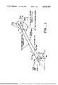
- FIG. 1 illustrates the basic burst height compensation technique of the present invention
- FIG. 2 is a block diagram illustrating the signal flow in the present invention.
- the inclined ellipsoid 10 represents the weapon system delivery error distribution at reentry into the atmosphere (e.g. approximately 400,000 feet altitude) with the nominal trajectory represented by line 12 from the nominal reentry location 14 to the nominal burst location 16 at altitude h B above a target 18.
- the nominal trajectory is defined at reentry by an initial velocity V o along an initial path angle ⁇ o with respect to the horizontal.
- the delivery error is assumed to be along the line of downrange means (LOM) 20 which is defined by the locus of the midpoint of the downrange dispersion ( ⁇ X o ) at each altitude slice ( ⁇ h o ) through the inclined ellipse 10.
- LOM 20 is represented by a line through the center of the error ellipse 10 inclined at an angle ⁇ E with the horizontal.
- the fire control system 24 of the launch platform provides preset inputs to the missile guidance system 26 and a computer 28 in the burst height compensation system 30 on board the reentry body. These preset inputs define the nominal trajectory of the reentry body and the predicted weapon system delivery error.
- the preset data provided to the computer 28 includes the reentry time t o and nominal trajectory parameters including the initial reentry velocity V o , the initial reentry path angle ⁇ o , the nominal path length from reentry to a specific altitude S NR , and the nominal path length from reentry to the burst locations S NB .
- the preset data to the computer 28 also includes the angle of inclination ⁇ E of the line of downrange means 20 and an angle of inclination ⁇ B of a line-of-means 29 at the fuzing location which is selected to optimize the burst location for the actual trajectory.
- the burst height compensation system 30 is activated and the missile guidance system 26 sends a signal to start a flight clock 32 in the burst height compensation system at a predetermined time from guidance start.
- the burst height compensation system 30 begins on-board computations which measure the actual path length of the reentry body after reentry. Based on the measured longitudinal acceleration from an accelerometer 34 and the preset inputs from the platform fire control system 24, the computer 28 calculates the actual trajectory according to the following equations:
- V is the velocity of reentry body
- ⁇ is the path angle of the reentry body
- a x is the measured longitudinal acceleration of the reentry body
- g is the calculated acceleration of gravity
- r is the distance of the reentry body from the center of the earth
- S M is the measured path length from t o .
- S MB is the measured path length from t o to the desired burst height
- K.sub. ⁇ is a gain factor chosen to provide the optimum fuzing location.
- the computer 28 begins integration according to equations (1)-(7) to provide the reentry body path length S M .
- S M equals S MB
- the fuze signal is sent to the fire set 38.
- the fuzing location is shown as lying on the line-of-means 29, it is noted that the fuzing location as determined by equation (7) may be located at any point on the flight path 22 after the radar fix altitude to provide optimum burst location.
- the present invention provides the ability to partially compensate for some of the errors generated by the weapon delivery system and also for some of the errors induced during the vehicle's passage through the atmosphere such as those due to winds in the plane of the trajectory, density variations in the atmosphere from the assumed density, and variations in the drag and lift from the assumed nominal reentry body performance.
- a radar altimeter could be used to measure altitude at a specified time in order to determine the path length traveled from represntative location A to the alternate radar fix. Then the same distance from point A to the fuze point B would be calculated by a different but similar algorithm shown in equation (6).
Abstract
Description
V=V.sub.o +∫(a.sub.x -g sin γ)dt (1)
γ=γ.sub.o +∫g/V (1-V.sup.2 /gr) cos γdt (2)
r=r.sub.o +∫V sin γdt (3)
g=g.sub.o r.sub.o.sup.2 /r.sup.2 (4)
S.sub.M =∫Vdt (5)
S.sub.MB =S.sub.NB +(S.sub.MR -S.sub.NR) K.sub.θ (6)
K.sub.θ =f(γ.sub.o, θ.sub.E, θ.sub.B, V.sub.o, etc.) (7)
Claims (4)
Priority Applications (1)
| Application Number | Priority Date | Filing Date | Title |
|---|---|---|---|
| US06/418,895 US4456202A (en) | 1982-09-16 | 1982-09-16 | Burst height compensation |
Applications Claiming Priority (1)
| Application Number | Priority Date | Filing Date | Title |
|---|---|---|---|
| US06/418,895 US4456202A (en) | 1982-09-16 | 1982-09-16 | Burst height compensation |
Publications (1)
| Publication Number | Publication Date |
|---|---|
| US4456202A true US4456202A (en) | 1984-06-26 |
Family
ID=23659998
Family Applications (1)
| Application Number | Title | Priority Date | Filing Date |
|---|---|---|---|
| US06/418,895 Expired - Fee Related US4456202A (en) | 1982-09-16 | 1982-09-16 | Burst height compensation |
Country Status (1)
| Country | Link |
|---|---|
| US (1) | US4456202A (en) |
Cited By (5)
| Publication number | Priority date | Publication date | Assignee | Title |
|---|---|---|---|---|
| US4662580A (en) * | 1985-06-20 | 1987-05-05 | The United States Of America As Represented By The Secretary Of The Navy | Simple diver reentry method |
| US5507452A (en) * | 1994-08-24 | 1996-04-16 | Loral Corp. | Precision guidance system for aircraft launched bombs |
| US5522567A (en) * | 1994-12-28 | 1996-06-04 | Rockwell International Corp. | Energy management system for a gliding vehicle |
| US7249730B1 (en) * | 2004-09-23 | 2007-07-31 | United States Of America As Represented By The Secretary Of The Army | System and method for in-flight trajectory path synthesis using the time sampled output of onboard sensors |
| US7533612B1 (en) * | 2004-09-23 | 2009-05-19 | The United States Of America As Represented By The Secretary Of The Army | Projectile height of burst determination method and system |
Citations (2)
| Publication number | Priority date | Publication date | Assignee | Title |
|---|---|---|---|---|
| US3784800A (en) * | 1971-05-27 | 1974-01-08 | Equipments Navigation Aerodrom | Systems for surveying and correcting trajectories |
| US3990657A (en) * | 1974-04-22 | 1976-11-09 | The United States Of America As Represented By The Secretary Of The Navy | Method and apparatus for reducing ballistic missile range errors due to viscosity uncertainties (U) |
-
1982
- 1982-09-16 US US06/418,895 patent/US4456202A/en not_active Expired - Fee Related
Patent Citations (2)
| Publication number | Priority date | Publication date | Assignee | Title |
|---|---|---|---|---|
| US3784800A (en) * | 1971-05-27 | 1974-01-08 | Equipments Navigation Aerodrom | Systems for surveying and correcting trajectories |
| US3990657A (en) * | 1974-04-22 | 1976-11-09 | The United States Of America As Represented By The Secretary Of The Navy | Method and apparatus for reducing ballistic missile range errors due to viscosity uncertainties (U) |
Cited By (5)
| Publication number | Priority date | Publication date | Assignee | Title |
|---|---|---|---|---|
| US4662580A (en) * | 1985-06-20 | 1987-05-05 | The United States Of America As Represented By The Secretary Of The Navy | Simple diver reentry method |
| US5507452A (en) * | 1994-08-24 | 1996-04-16 | Loral Corp. | Precision guidance system for aircraft launched bombs |
| US5522567A (en) * | 1994-12-28 | 1996-06-04 | Rockwell International Corp. | Energy management system for a gliding vehicle |
| US7249730B1 (en) * | 2004-09-23 | 2007-07-31 | United States Of America As Represented By The Secretary Of The Army | System and method for in-flight trajectory path synthesis using the time sampled output of onboard sensors |
| US7533612B1 (en) * | 2004-09-23 | 2009-05-19 | The United States Of America As Represented By The Secretary Of The Army | Projectile height of burst determination method and system |
Similar Documents
| Publication | Publication Date | Title |
|---|---|---|
| US5647558A (en) | Method and apparatus for radial thrust trajectory correction of a ballistic projectile | |
| US4542870A (en) | SSICM guidance and control concept | |
| US3179355A (en) | Guidance and control system | |
| EP0752573A2 (en) | Missile fuzing system | |
| US6481666B2 (en) | Method and system for guiding submunitions | |
| US3695555A (en) | Gun-launched glide vehicle with a mid-course and terminal guidance control system | |
| US5001476A (en) | Warning system for tactical aircraft | |
| US6345785B1 (en) | Drag-brake deployment method and apparatus for range error correction of spinning, gun-launched artillery projectiles | |
| US7815115B2 (en) | Method of determining a fire guidance solution | |
| CN111692919B (en) | Precise guidance control method for aircraft with ultra-close range | |
| US6450456B1 (en) | Airborne safe landing power control system and method | |
| US6138944A (en) | Scatterider guidance system for a flying object based on maintenance of minimum distance between the designating laser beam and the longitudinal axis of the flying object | |
| US3568954A (en) | Directional control-automatic meteorological compensation (d.c.-automet) inertial guidance system for artillery missiles | |
| EP0636862B1 (en) | Inertial measurement unit and method for improving its measurement accuracy | |
| US4750688A (en) | Line of sight missile guidance | |
| US4456202A (en) | Burst height compensation | |
| US8433460B1 (en) | Onboard sensor suite for determining projectile velocity | |
| US4625647A (en) | Weapon system and missile for the structural destruction of an aerial target by means of a focussed charge | |
| Ross et al. | A transfer alignment algorithm study based on actual flight test data from a tactical air-to-ground weapon launch | |
| US5341743A (en) | Directed-effect munition | |
| US20100019078A1 (en) | Missile guidance system | |
| US4383662A (en) | Ideal trajectory shaping for anti-armor missiles via gimbal angle controller autopilot | |
| US4662580A (en) | Simple diver reentry method | |
| US4901946A (en) | System for carrier guidance by laser beam and pyrotechnic thrusters | |
| Pamadi et al. | Assessment of a GPS guided spinning projectile using an accelerometer-only IMU |
Legal Events
| Date | Code | Title | Description |
|---|---|---|---|
| AS | Assignment |
Owner name: UNITED STATES OF AMERICA, AS REPRESENTED BY THE NA Free format text: ASSIGNS THE ENTIRE INTEREST, SUBJECT TO LICENSE RECITED;ASSIGNOR:LOCKHEED MISSILES & SPACE COMPANY, INC.;REEL/FRAME:004046/0384 Effective date: 19820902 Owner name: LOCKHEED MISSILES & SPACE COMPANY, INC.; SUNNYVALE Free format text: ASSIGNMENT OF ASSIGNORS INTEREST.;ASSIGNORS:PRICE, DONALD A.;LOUIS, CHARLES A. III;REEL/FRAME:004046/0383 Effective date: 19820827 Owner name: LOCKHEED MISSILES & SPACE COMPANY, INC., CALIFORNI Free format text: ASSIGNMENT OF ASSIGNORS INTEREST;ASSIGNORS:PRICE, DONALD A.;LOUIS, CHARLES A. III;REEL/FRAME:004046/0383 Effective date: 19820827 |
|
| REMI | Maintenance fee reminder mailed | ||
| LAPS | Lapse for failure to pay maintenance fees | ||
| STCH | Information on status: patent discontinuation |
Free format text: PATENT EXPIRED DUE TO NONPAYMENT OF MAINTENANCE FEES UNDER 37 CFR 1.362 |
|
| FP | Lapsed due to failure to pay maintenance fee |
Effective date: 19870626 |