US4455021A - Method of stringing or restringing a tennis racket - Google Patents
Method of stringing or restringing a tennis racket Download PDFInfo
- Publication number
- US4455021A US4455021A US06/384,091 US38409182A US4455021A US 4455021 A US4455021 A US 4455021A US 38409182 A US38409182 A US 38409182A US 4455021 A US4455021 A US 4455021A
- Authority
- US
- United States
- Prior art keywords
- string
- racquet
- extension
- longitudinal
- clamp
- Prior art date
- Legal status (The legal status is an assumption and is not a legal conclusion. Google has not performed a legal analysis and makes no representation as to the accuracy of the status listed.)
- Expired - Fee Related
Links
Images


Classifications
-
- A—HUMAN NECESSITIES
- A63—SPORTS; GAMES; AMUSEMENTS
- A63B—APPARATUS FOR PHYSICAL TRAINING, GYMNASTICS, SWIMMING, CLIMBING, OR FENCING; BALL GAMES; TRAINING EQUIPMENT
- A63B51/00—Stringing tennis, badminton or like rackets; Strings therefor; Maintenance of racket strings
- A63B51/14—Arrangements for stringing, e.g. for controlling the tension of the strings during stringing
- A63B51/143—Hand-held string-tensioning devices
-
- Y—GENERAL TAGGING OF NEW TECHNOLOGICAL DEVELOPMENTS; GENERAL TAGGING OF CROSS-SECTIONAL TECHNOLOGIES SPANNING OVER SEVERAL SECTIONS OF THE IPC; TECHNICAL SUBJECTS COVERED BY FORMER USPC CROSS-REFERENCE ART COLLECTIONS [XRACs] AND DIGESTS
- Y10—TECHNICAL SUBJECTS COVERED BY FORMER USPC
- Y10T—TECHNICAL SUBJECTS COVERED BY FORMER US CLASSIFICATION
- Y10T29/00—Metal working
- Y10T29/49—Method of mechanical manufacture
- Y10T29/49718—Repairing
Definitions
- clamps are employed to temporarily hold the tension on a section of string which is being pulled between two holes in opposite sides of the racquet.
- One type of the said clamp functions by temporarily fixing the said string to an adjacent string which has previously been pulled between a set of holes. This type of clamp is referred to as a dual string clamp.
- Dual string clamps are inexpensive and easy to use; however, they have several disadvantages as compared to more expensive clamping systems. For example, when using a dual string clamp, the first two longitudinal strings to be installed in the racquet must be pulled as a pair. If the first string were pulled by itself there would be no adjacent string to clamp it to. Unfortunately, the pulling of these strings as a pair causes a loss in tension on the first longitudinal string. In a similar manner, a loss in tension on the first horizontal string results from pulling the first two horizontal strings as a pair when using a dual string clamp.
- a second disadvantage to dual string clamp systems pertains to stringing or restringing oversized racquets.
- the adjacent strings in oversized racquets are spaced farther apart than are the strings in smaller racquets. It can be difficult, therefore, to position a dual string clamp over two adjacent strings in a oversized racquet.
- This invention provides a small and inexpensive bracket which can be attached to a racquet which is being strung or restrung. From one end of the said bracket protudes an extension having size and shape which allow it to be grasped by a dual string clamp's own clamping mechanism.
- the dual string clamp simultaneously grasps the newly pulled string as usual. Since the said newly pulled string is now fixed to the dual string clamp, which is fixed to the invention, which in turn is fixed to the racquet frame, the newly pulled string cannot move. Its tension is therefore maintained. Its free end is now pulled between the next set of holes; thus the normal stringing process is continued.
- An object of this invention is to allow the first longitudinal and horizontal strings to be pulled alone when using a dual string clamp. This eliminates the tension loss on the first longitudinal and horizontal strings which results from pulling these strings in pairs with the second longitudinal and second horizontal strings respectively.
- a second object of the invention is to eliminate the difficulty encountered when using a dual string clamp to string or restring an oversized racquet.
- FIG. 1 is a side view of the invention in its entirety.
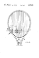
- FIG. 2 is a top view of the invention being used with a dual string clamp to hold tension on the first longitudinal string of a racquet which is being strung.
- FIG. 3 is a top view of the invention being used with a dual string clamp to hold tension on the first horizontal string of a racquet which is being strung.
- the invention in its best form consists of a modified pair of locking pliers 1 connected to an extension 2.
- the invention in this form is constructed by filing or sawing a circular groove 3 in the jaw 11 of the locking pliers 1.
- the extension 2 is made of flexible wire having a diameter equal to that of average size tennis string.
- the said extension 2 is wrapped around the groove 3 and then wrapped around itself several times. This construction allows the said extension 2 to swivel from side to side with respect to the said locking pliers 1 but, restricts all front to back and top to bottom movement by the said extension 2.
- the inside edges of the locking plier's jaws are covered with rubber pads 4 & 5 which may be glued in place.
- the said first longitudinal string 8 is inserted between the set of holes located immediately to one side of the racquets center.
- the said first longitudinal string 8 is secured at one end as is usual.
- the method for securing the said first longitudinal string 8 is not shown in FIG. 2 because it is standard procedure.
- the locking pliers 1 are clamped to the racquet 18 so that the said locking pliers 1 lie next to the first longitudinal string 8 in such a way that the pad 5 is in contact with the outside edge 6 of the racquet 18 and the pad 4 is in contact with the inside edge 7 of the racquet 18.
- the extension 2 shall lie parallel to the first longitudinal string 8 such that the distance between the said extension 2 and the said first longitudinal string 8 is aproximately equal to the average distance between strings on a tennis racquet.
- the said locking pliers 1 shall lie on the opposite side of the first longitudinal string 8 from which the second longitudinal string will be placed. For example, if the second longitudinal string will be placed to the left of the first longitudinal string 8 then, the invention should be placed to the right of the said first longitudinal string 8. This is the positioning illustrated in FIG. 2. Next, the free end 12 of the first longitudinal string 8 is pulled in the usual manner, and a dual string clamp 10 is used to fix the first longitudinal string 8 to the extension 2 thereby maintaining the tension on the first longitudinal string 8.
- FIG. 1 the free end 12 of the first longitudinal string 8 is pulled in the usual manner, and a dual string clamp 10 is used to fix the first longitudinal string 8 to the extension 2 thereby maintaining the tension on the first longitudinal string 8.
- the dual string clamp 10 should be placed as close to the junction of the extension 2 with the locking pliers 1 as possible. For the purpose of clarity in both FIG. 2 and FIG. 3, the distance between the dual string clamp and the junction of the extension 2 with the locking pliers 1 was exagerated.)
- the free end 12 of the first longitudinal string 8 can be inserted through the next set of holes 13 & -4, pulled, and clamped, using the dual string clamp, to the first longitudinal string 8 as is standard procedure.
- FIG. 3 illustrates the invention being used to hold tension on the first horizontal string 9.
- the locking pliers 1 are clamped to the racquet frame 18 so that the said locking pliers 1 lie next to the first horizontal string 9 in such a way that the pad 5 is in contact with the outside edge 6 of the racquet 18 and the pad 4 is in contact with the inside edge 7 of the racquet 18.
- the extension 2 shall lie parallel to the first horizontal string 9 such that the distance between the said first horizontal string 9 and the said extension 2 is aproximately equal to the distance between strings on a standard tennis racquet.
- the said locking pliers 1 shall lie on the opposite side of the first horizontal string 9 from which the second horizontal string will be placed.
- the extension 2 may lie either above or below the longitudinal strings which by convention are installed in the racquet frame before the horizontal strings.
- FIG. 3 the said extension 2 is depicted as being below the longitudinal strings.
- the free end 15 of the first horizontal string 9 is pulled in the usual manner, and a dual string clamp 10 is used to fix the first horizontal string 9 to the said extension 2 thereby maintaining tension on the first horizontal string 9.
- FIG. 3 illustrates the set-up described above.
- the free end 15 of the first horizontal string 9 is inserted in the next set of holes 16 & 17, pulled, and clamped using the dual string clamp 10 to the first horizontal string 9 thus the normal stringing process is continued.
Landscapes
- Health & Medical Sciences (AREA)
- General Health & Medical Sciences (AREA)
- Physical Education & Sports Medicine (AREA)
- Supports For Plants (AREA)
Abstract
A hand tool for use in stringing or restringing tennis or similar type racquets, consisting of a bracket that clamps to the recquet. The bracket has an extension protruding from it which acts as an anchor for a dual string clamp, allowing the dual string clamp to hold the tension on any newly pulled string in the racquet without using the previously pulled string as an anchor.
Description
During the process of stringing or restringing a tennis or similar type racquet, clamps are employed to temporarily hold the tension on a section of string which is being pulled between two holes in opposite sides of the racquet. One type of the said clamp functions by temporarily fixing the said string to an adjacent string which has previously been pulled between a set of holes. This type of clamp is referred to as a dual string clamp.
Dual string clamps are inexpensive and easy to use; however, they have several disadvantages as compared to more expensive clamping systems. For example, when using a dual string clamp, the first two longitudinal strings to be installed in the racquet must be pulled as a pair. If the first string were pulled by itself there would be no adjacent string to clamp it to. Unfortunately, the pulling of these strings as a pair causes a loss in tension on the first longitudinal string. In a similar manner, a loss in tension on the first horizontal string results from pulling the first two horizontal strings as a pair when using a dual string clamp.
A second disadvantage to dual string clamp systems pertains to stringing or restringing oversized racquets. The adjacent strings in oversized racquets are spaced farther apart than are the strings in smaller racquets. It can be difficult, therefore, to position a dual string clamp over two adjacent strings in a oversized racquet.
This invention provides a small and inexpensive bracket which can be attached to a racquet which is being strung or restrung. From one end of the said bracket protudes an extension having size and shape which allow it to be grasped by a dual string clamp's own clamping mechanism. The dual string clamp simultaneously grasps the newly pulled string as usual. Since the said newly pulled string is now fixed to the dual string clamp, which is fixed to the invention, which in turn is fixed to the racquet frame, the newly pulled string cannot move. Its tension is therefore maintained. Its free end is now pulled between the next set of holes; thus the normal stringing process is continued.
An object of this invention is to allow the first longitudinal and horizontal strings to be pulled alone when using a dual string clamp. This eliminates the tension loss on the first longitudinal and horizontal strings which results from pulling these strings in pairs with the second longitudinal and second horizontal strings respectively.
A second object of the invention is to eliminate the difficulty encountered when using a dual string clamp to string or restring an oversized racquet.
FIG. 1 is a side view of the invention in its entirety.
FIG. 2 is a top view of the invention being used with a dual string clamp to hold tension on the first longitudinal string of a racquet which is being strung.
FIG. 3 is a top view of the invention being used with a dual string clamp to hold tension on the first horizontal string of a racquet which is being strung.
Referring to FIG. 1, the invention in its best form consists of a modified pair of locking pliers 1 connected to an extension 2. The invention in this form is constructed by filing or sawing a circular groove 3 in the jaw 11 of the locking pliers 1. The extension 2 is made of flexible wire having a diameter equal to that of average size tennis string. The said extension 2 is wrapped around the groove 3 and then wrapped around itself several times. This construction allows the said extension 2 to swivel from side to side with respect to the said locking pliers 1 but, restricts all front to back and top to bottom movement by the said extension 2. In order to protect the surface of the racquet, the inside edges of the locking plier's jaws are covered with rubber pads 4 & 5 which may be glued in place.
Referring now to FIG. 2, in order to use the invention to hold tension on the first longitudinal string 8, the said first longitudinal string 8 is inserted between the set of holes located immediately to one side of the racquets center. The said first longitudinal string 8 is secured at one end as is usual. (The method for securing the said first longitudinal string 8 is not shown in FIG. 2 because it is standard procedure.) The locking pliers 1 are clamped to the racquet 18 so that the said locking pliers 1 lie next to the first longitudinal string 8 in such a way that the pad 5 is in contact with the outside edge 6 of the racquet 18 and the pad 4 is in contact with the inside edge 7 of the racquet 18. Furthermore, the extension 2 shall lie parallel to the first longitudinal string 8 such that the distance between the said extension 2 and the said first longitudinal string 8 is aproximately equal to the average distance between strings on a tennis racquet. In addition, the said locking pliers 1 shall lie on the opposite side of the first longitudinal string 8 from which the second longitudinal string will be placed. For example, if the second longitudinal string will be placed to the left of the first longitudinal string 8 then, the invention should be placed to the right of the said first longitudinal string 8. This is the positioning illustrated in FIG. 2. Next, the free end 12 of the first longitudinal string 8 is pulled in the usual manner, and a dual string clamp 10 is used to fix the first longitudinal string 8 to the extension 2 thereby maintaining the tension on the first longitudinal string 8. FIG. 2 illustrates the set-up described above. (Note that for maximum efficiency, the dual string clamp 10 should be placed as close to the junction of the extension 2 with the locking pliers 1 as possible. For the purpose of clarity in both FIG. 2 and FIG. 3, the distance between the dual string clamp and the junction of the extension 2 with the locking pliers 1 was exagerated.) At this time, the free end 12 of the first longitudinal string 8 can be inserted through the next set of holes 13 & -4, pulled, and clamped, using the dual string clamp, to the first longitudinal string 8 as is standard procedure.
FIG. 3 illustrates the invention being used to hold tension on the first horizontal string 9. The locking pliers 1 are clamped to the racquet frame 18 so that the said locking pliers 1 lie next to the first horizontal string 9 in such a way that the pad 5 is in contact with the outside edge 6 of the racquet 18 and the pad 4 is in contact with the inside edge 7 of the racquet 18. Furthermore, the extension 2 shall lie parallel to the first horizontal string 9 such that the distance between the said first horizontal string 9 and the said extension 2 is aproximately equal to the distance between strings on a standard tennis racquet. In addition, the said locking pliers 1 shall lie on the opposite side of the first horizontal string 9 from which the second horizontal string will be placed. Finally, it must be noted that the extension 2 may lie either above or below the longitudinal strings which by convention are installed in the racquet frame before the horizontal strings. In FIG. 3, the said extension 2 is depicted as being below the longitudinal strings. Next, the free end 15 of the first horizontal string 9 is pulled in the usual manner, and a dual string clamp 10 is used to fix the first horizontal string 9 to the said extension 2 thereby maintaining tension on the first horizontal string 9. FIG. 3 illustrates the set-up described above. At this time, the free end 15 of the first horizontal string 9 is inserted in the next set of holes 16 & 17, pulled, and clamped using the dual string clamp 10 to the first horizontal string 9 thus the normal stringing process is continued.
To use the invention to install any other string on the racquet (especially useful when stringing an oversized racquet) the directions in one of the two preceeding paragraphs should be followed. The former paragraph for any longitudinal string and the latter paragraph for any horizontal string. The locking pliers 1 being placed next to the string which is being installed instead of next to the first longitudinal or horizontal string as described in the preceeding paragraphs.
While this is a description of the invention in its best form, modifications may be made which change neither the spirit nor scope of the invention. Possible modifications include, but are not limited to, changing the material from which the extension 2 is constructed from and/or substituting the locking pliers 1 with a different system for holding the said extension 2 to the racquet frame 18.
Claims (1)
1. A method of stringing or restringing a tennis racquet comprising the steps of: employing a bracket, said bracket having an elongated extension extending therefrom; clamping said bracket to said racquet such that the extension lies parallel and proximate to a string being strung; applying a clamp means simultaneously to said extension and to said string to be strung so as to temporarily retain said string against movement relative to said extension such that a predetermined tension can be maintained on said string.
Priority Applications (1)
| Application Number | Priority Date | Filing Date | Title |
|---|---|---|---|
| US06/384,091 US4455021A (en) | 1982-06-01 | 1982-06-01 | Method of stringing or restringing a tennis racket |
Applications Claiming Priority (1)
| Application Number | Priority Date | Filing Date | Title |
|---|---|---|---|
| US06/384,091 US4455021A (en) | 1982-06-01 | 1982-06-01 | Method of stringing or restringing a tennis racket |
Publications (1)
| Publication Number | Publication Date |
|---|---|
| US4455021A true US4455021A (en) | 1984-06-19 |
Family
ID=23515998
Family Applications (1)
| Application Number | Title | Priority Date | Filing Date |
|---|---|---|---|
| US06/384,091 Expired - Fee Related US4455021A (en) | 1982-06-01 | 1982-06-01 | Method of stringing or restringing a tennis racket |
Country Status (1)
| Country | Link |
|---|---|
| US (1) | US4455021A (en) |
Cited By (5)
| Publication number | Priority date | Publication date | Assignee | Title |
|---|---|---|---|---|
| US5846146A (en) * | 1996-12-11 | 1998-12-08 | Grusd; Selwyn | Device for repairing or replacing a broken string on a racket |
| US5863267A (en) * | 1997-12-24 | 1999-01-26 | Choi; In Y. | Racket device and associated method of stringing a racket |
| US6132325A (en) * | 1997-06-25 | 2000-10-17 | Bertolotti; Fabio P | Interlocking string network for sport rackets |
| US6506134B2 (en) | 1997-06-25 | 2003-01-14 | Fabio Paolo Bertolotti | Interlocking string network for sports rackets |
| US20160107922A1 (en) * | 2013-07-11 | 2016-04-21 | Shenzhen China Star Optoelectronics Technology Co., Ltd. | Buffering structure and clamping device using same |
Citations (3)
| Publication number | Priority date | Publication date | Assignee | Title |
|---|---|---|---|---|
| US2554020A (en) * | 1949-03-26 | 1951-05-22 | Sophie Dabrowski | Barbed-wire fence builder |
| US3284050A (en) * | 1964-08-14 | 1966-11-08 | Meyer Alfons De | Clamping tensioned strings for the stringing or restringing of rackets |
| US4326713A (en) * | 1979-02-12 | 1982-04-27 | Balaban J A | Racket stringing apparatus and method |
-
1982
- 1982-06-01 US US06/384,091 patent/US4455021A/en not_active Expired - Fee Related
Patent Citations (3)
| Publication number | Priority date | Publication date | Assignee | Title |
|---|---|---|---|---|
| US2554020A (en) * | 1949-03-26 | 1951-05-22 | Sophie Dabrowski | Barbed-wire fence builder |
| US3284050A (en) * | 1964-08-14 | 1966-11-08 | Meyer Alfons De | Clamping tensioned strings for the stringing or restringing of rackets |
| US4326713A (en) * | 1979-02-12 | 1982-04-27 | Balaban J A | Racket stringing apparatus and method |
Cited By (5)
| Publication number | Priority date | Publication date | Assignee | Title |
|---|---|---|---|---|
| US5846146A (en) * | 1996-12-11 | 1998-12-08 | Grusd; Selwyn | Device for repairing or replacing a broken string on a racket |
| US6132325A (en) * | 1997-06-25 | 2000-10-17 | Bertolotti; Fabio P | Interlocking string network for sport rackets |
| US6506134B2 (en) | 1997-06-25 | 2003-01-14 | Fabio Paolo Bertolotti | Interlocking string network for sports rackets |
| US5863267A (en) * | 1997-12-24 | 1999-01-26 | Choi; In Y. | Racket device and associated method of stringing a racket |
| US20160107922A1 (en) * | 2013-07-11 | 2016-04-21 | Shenzhen China Star Optoelectronics Technology Co., Ltd. | Buffering structure and clamping device using same |
Similar Documents
| Publication | Publication Date | Title |
|---|---|---|
| FR2642655B1 (en) | APPARATUS FOR STRINGING A TENNIS RACKET | |
| US5441268A (en) | Golf putting accessory | |
| US3994495A (en) | Tennis racket | |
| SE421856B (en) | HALLERS FOR FIXING IN PARTICULAR SAFETY GLASSOGON AT A SAFETY HELMET | |
| US4455021A (en) | Method of stringing or restringing a tennis racket | |
| US3860240A (en) | Volleyball net antenna clamp | |
| US4937946A (en) | Masonry line stretcher | |
| TW201636076A (en) | System for tensioning a racket string and stringing machine comprising such a system | |
| JPS63276B2 (en) | ||
| US20030223808A1 (en) | Length-adjusting device for elastic cord member | |
| JPH0241341B2 (en) | ||
| JPH04501072A (en) | A method for stringing individual strings on a ball game racket and an apparatus for carrying out the method | |
| US4047726A (en) | Device for bundling skis together in pairs | |
| US3302950A (en) | Racket stringing machine | |
| US4359213A (en) | Tension clamp for three or more direction string networks | |
| US5639086A (en) | Universal stringing machine for sports racquets | |
| US4883635A (en) | Means for manually holding a stack of karate boards | |
| US4084321A (en) | Mason's guide | |
| US4484742A (en) | Stringing tool for tennis rackets and the like | |
| GB1534755A (en) | Method of making a tennis badminton or similar racket net net obtained by this method and racket comprising this ne | |
| JPS5911018Y2 (en) | Racket fixture | |
| US3284050A (en) | Clamping tensioned strings for the stringing or restringing of rackets | |
| US2626438A (en) | Line-attaching device | |
| RU1672644C (en) | Clamping device for keeping tightening of racket strings | |
| DE3778796D1 (en) | BUNDLE TAPING MACHINE. |
Legal Events
| Date | Code | Title | Description |
|---|---|---|---|
| REMI | Maintenance fee reminder mailed | ||
| FPAY | Fee payment |
Year of fee payment: 4 |
|
| SULP | Surcharge for late payment | ||
| REMI | Maintenance fee reminder mailed | ||
| LAPS | Lapse for failure to pay maintenance fees | ||
| FP | Expired due to failure to pay maintenance fee |
Effective date: 19920621 |
|
| STCH | Information on status: patent discontinuation |
Free format text: PATENT EXPIRED DUE TO NONPAYMENT OF MAINTENANCE FEES UNDER 37 CFR 1.362 |