US4452580A - Deep drawing machine for manufacturing receptacles made out of thermoplastic foil material - Google Patents
Deep drawing machine for manufacturing receptacles made out of thermoplastic foil material Download PDFInfo
- Publication number
- US4452580A US4452580A US06/446,731 US44673182A US4452580A US 4452580 A US4452580 A US 4452580A US 44673182 A US44673182 A US 44673182A US 4452580 A US4452580 A US 4452580A
- Authority
- US
- United States
- Prior art keywords
- banderole
- hollow mold
- deep
- slider
- drawing machine
- Prior art date
- Legal status (The legal status is an assumption and is not a legal conclusion. Google has not performed a legal analysis and makes no representation as to the accuracy of the status listed.)
- Expired - Lifetime
Links
- 239000011888 foil Substances 0.000 title claims abstract description 21
- 239000000463 material Substances 0.000 title claims abstract description 13
- 229920001169 thermoplastic Polymers 0.000 title claims abstract description 8
- 239000004416 thermosoftening plastic Substances 0.000 title claims abstract description 8
- 238000004519 manufacturing process Methods 0.000 title claims abstract description 7
- 238000004804 winding Methods 0.000 claims abstract description 38
- 238000004891 communication Methods 0.000 claims abstract description 10
- 230000002093 peripheral effect Effects 0.000 claims abstract description 7
- 238000010438 heat treatment Methods 0.000 claims abstract description 6
- 239000012530 fluid Substances 0.000 claims 1
- 238000000034 method Methods 0.000 description 3
- 238000006073 displacement reaction Methods 0.000 description 1
- 229940079593 drug Drugs 0.000 description 1
- 239000003814 drug Substances 0.000 description 1
- 235000013305 food Nutrition 0.000 description 1
- 238000003780 insertion Methods 0.000 description 1
- 230000037431 insertion Effects 0.000 description 1
- 239000007788 liquid Substances 0.000 description 1
- 238000002483 medication Methods 0.000 description 1
- 238000012986 modification Methods 0.000 description 1
- 230000004048 modification Effects 0.000 description 1
- 238000004806 packaging method and process Methods 0.000 description 1
- 235000011837 pasties Nutrition 0.000 description 1
- 230000002787 reinforcement Effects 0.000 description 1
- 238000007789 sealing Methods 0.000 description 1
- 238000007493 shaping process Methods 0.000 description 1
- 239000000126 substance Substances 0.000 description 1
Images


Classifications
-
- B—PERFORMING OPERATIONS; TRANSPORTING
- B29—WORKING OF PLASTICS; WORKING OF SUBSTANCES IN A PLASTIC STATE IN GENERAL
- B29C—SHAPING OR JOINING OF PLASTICS; SHAPING OF MATERIAL IN A PLASTIC STATE, NOT OTHERWISE PROVIDED FOR; AFTER-TREATMENT OF THE SHAPED PRODUCTS, e.g. REPAIRING
- B29C51/00—Shaping by thermoforming, i.e. shaping sheets or sheet like preforms after heating, e.g. shaping sheets in matched moulds or by deep-drawing; Apparatus therefor
- B29C51/16—Lining or labelling
- B29C51/165—Lining or labelling combined with the feeding or the shaping of the lining or the labels
- B29C51/167—Lining or labelling combined with the feeding or the shaping of the lining or the labels of a continuous strip
Definitions
- the invention relates to a deep-drawing machine for manufacturing containers or receptacles made out of thermoplastic foil material which includes an arrangement for introducing sections of banderole-shaped strips into hollow molds prior to a deep drawing step.
- a deep-drawing machine of this type permits an economic and hygienic packaging of substances in liquid or pasty form, for example, medications or food stuffs.
- the deep-drawing machine includes means for manufacturing a container, means for filling the container, and means for sealing it. Furthermore, there are means provided to affix onto the container, for example, decorative material, by means of a banderole-like strip which is connected to the exterior wall of the container and is permanently bonded to it by means of being sealed thereon.
- a deep-drawing machine of this type is, for example, disclosed in German published patent application No. 23 65 028.
- the arrangement for inserting the banderole-like strip sections into the hollow mold encompasses a slidably axially movable winding mandrel which serves to act on the banderole-like strip sections.
- the winding mandrel projects in a first position completely into the hollow mold, whereas in its other second position its front end forms the bottom of the mold during the forming process.
- the deep-drawing machine of the invention for manufacturing containers out of thermoplastic foil material has an arrangement for inserting into a hollow mold prior to the deep drawing step a banderole-shaped strip section.
- the machine includes support means for a roll of foil material, means for transporting the foil material, and a heating arrangement as well as a forming arrangement.
- Said forming arrangement consists of a stationary counter mold and the hollow mold movable perpendicular to the foil plane, which is pressed against a counter mold after the heating pressure medium and thereby simultaneously the strip sections, which have been introduced into the hollow mold, are sealed onto the container.
- the arrangement for inserting the banderole-shaped strip sections into the hollow mold includes a winding mandrel which is stationary with respect to the axially movable hollow mold, in the outer peripheral surface of which winding mandrel there are disposed a plurality of bores which are adapted to be placed in communication with a vacuum source.
- a slider which is glidably mounted relative to the hollow mold and the winding mandrel.
- the slider includes a recess, the height of which corresponds to the width of the banderole-shaped strip sections.
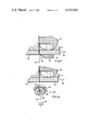
- FIG. 1 is a schematic cross-sectional view in the region of the hollow molds of the deep-drawing machine in which all parts of the arrangement, which are not immediately related to the invention, have been omitted, which cross-sectional view is taken along the line 1--1 of FIG. 2;
- FIG. 2 is a longitudinal sectional view taken along line 2--2 of FIG. 1;
- FIG. 3 is a plan view of the upper side of the glidably mounted slider
- FIG. 4 is a cross-sectional view of the glidably mounted slider taken along line 4--4 of FIG. 3;
- FIG. 5 is a partial view of the glidably mounted slider viewed in the direction in which the banderole-shaped strip section is introduced;
- FIG. 6 illustrates a first embodiment of a cutting arrangement for cutting the banderole-shaped strip sections
- FIG. 7 illustrates a further embodiment of a cutting arrangement for cutting the banderole-shaped strip sections.
- FIG. 8 is a cross-sectional view of a plurality of hollow molds arranged side-by-side in the cutting plane 1--1 according to FIG. 2.
- the principle of manufacturing of containers having banderole-shaped strips in a deep-drawing machine is already known. It consists in that the banderole-shaped strip, which can serve for decorative or reinforcement purposes, is inserted in a hollow mold, a thermoplastic preheated foil is placed over the open side of the hollow mold, and with the aid of a punch the thermoplastic foil is shaped while being introduced into the hollow mold and thereby is shaped into a container and for the final shaping the container receives the necessary shape by means of a pressure medium which acts on the punch side on the preshaped container and presses its walls against the inner surface of the hollow mold. Thereby the foil of the container is fixedly joined to the banderole-shaped strip which has been previously introduced into the hollow mold.
- the arrangement of the present invention departs from the aforedescribed conventional arrangement in that a non-rotatable winding mandrel 12 is provided (see FIG. 1), which is fixedly arranged relative to the axially movable hollow mold 11. Outside of the hollow mold 11 there is mounted at the bottom inlet side of the banderole-shaped strip sections 10 a slider 16 which is glidably mounted relative to the hollow mold 11 and the winding mandrel 12 (see FIGS. 3 to 5).
- This slider 16 has a plurality of inlet slots or recesses 17 the height of which correspond to the width of the banderole-shaped strips 10.
- the recess is advantageously widened by a funnel-shape at the bottom side confronting the exterior surface 18 of the slider 16 which faces away from the hollow mold 11.
- the glidable movement of the slider 16 is effected perpendicular to the plane of the banderole-shaped strip 10 and in a plane which is parallel to the non-illustrated path traversed by the foil and from which the containers are manufactured.
- the glidably mounted sliders 16 are reciprocable between essentially two operative positions, whereby in the first operative position of the slider 16 the recess 17 is in alignment with the inlet channel 19 for the banderole-shaped strip sections 10 in the hollow mold 11 (FIG. 1) and whereby in the second operative position of the slider 16 the recess 17 is disposed in alignment with the opening 15 in the exterior peripheral surface of the winding mandrel 12.
- the latter has two stops 20, 21 projecting in the direction of the hollow mold 11, which serve to abut against the exterior surfaces 22, 23 of the hollow mold 11 and in this manner limit the further movement of the slider 16 from its respective operative position.
- At least one adjustable screw 39 mounted in the stop 21 where it can be adjusted and then fixed in position, serves to exactly adjust the working positions of the glidably mounted slider 16.
- the inserting of the banderole-shaped strip 10 into the hollow mold 11 is carried out as follows:
- the slider 16 is disposed in its first working position (FIG. 1), in which the recess 17 is in alignment with the inlet channel 19. This operative position of the slider 16 is limited by the stop 21, which abuts against the exterior surface 23 of the hollow mold 11.
- the hollow mold 11, which is movable relative to the fixed winding mandrel 12 in the axial direction, in its first working position surrounds the winding mandrel 12 coaxially in such a way that there is formed between the inner wall 33 of the hollow mold 11 and the exterior wall 34 of the winding mandrel 12 a guide channel 35 for the banderole-shaped strips 10.
- the banderole-shaped strips 10 are paid out from a non-illustrated supply roller and by suitable means, for example, bilaterally disposed drive rollers 27 acting on the strip 10, is preferably step-wise guided through the recess 17 and the inlet channel 19 in such a way into the guide channel 35 that it abuts against the exterior curved surface 34 of the winding mandrel 12.
- the glidably mounted slider 16 has a nose-shaped projection 16' which projects normally from the exterior surface 18' of the slider 16 facing the winding mandrel 12 (FIGS. 2, 3 and 4).
- the banderole-shaped strip 10, which is introduced into the recess 17 is slidingly guided along the exterior surface 40 of the projection 16' (FIG. 3).
- the winding mandrel 12 has at its disposal a cut-out 41 at the level and depth of the projection 16' (FIG. 1) for the purpose of not hindering the movement of the slider 16 between its different operative positions.
- the forward end of the strip 10 reaches thereby the region of the exterior glide surface 34 of the winding mandrel 12 wherein a bore 14 is arranged which is in communication via a conduit 13' with a vacuum source 13, and as a result of such connection of the bore 14 with the vacuum source 13, the strip 10 is held against the exterior surface 34 of the winding mandrel 12.
- the banderole-shaped strip 10 is thereafter cut at a predetermined length, which in general has a maximum length corresponding to the exterior periphery of the to-be-banderoled container.
- the arrangement of the invention also makes it possible in an advantageous manner to work with shorter strip sections, the length of which may be less than the exterior periphery of the container, for example, when only portions of the exterior periphery of the container are to be provided with a banderole-shaped strip 10.
- the glidably mounted slider 16 is thereafter moved to the right (FIG. 1) into its second operative position which is limited by means of the engagement of stop 20 with the exterior surface 22 of mold 11.
- the further movement of the slider 16 is illustrated by means of the arrow 36.
- the rear end portion of the banderole-shaped strip 10, which is still disposed within the recess 17 of the slider 16 is moved by means of the slider 16 in a direction onto the exterior peripheral surface 34 of the winding mandrel 12 and thereby arrives at the region of the opening 15 for abutment.
- These openings 15, as is the case with the opening 14, are in communication with a vacuum source 13 via the conduit 13'.
- the rear end piece of the banderole-shaped strip 10 which has been moved by the slider 16, is held against the winding mandrel 12.
- the projection 16' has a slot 16" (see FIG. 4).
- the hollow mold 11 which is movable in the axial direction, moves so far relative to the stationary winding mandrel, that the openings 26 are disposed on the inner wall surface 25 of the hollow mold 11 at the level of the banderole-shaped strips 10 wound on the winding mandrel 12. Also the openings 26 are in communication with the vacuum source 13 at predetermined periods of time. First of all, the communication of the openings 14, 15 with the vacuum source 13 is interrupted, as a result of which the strips 10 are released from the exterior peripheral surface 34 of the winding mandrel 12 and, due to the inherent elastic tension, bears against the inner wall surface 25 of the hollow mold 11 in the region of the bores 26.
- the openings 26 are placed in communication with the vacuum source, whereby the strip 10 is firmly held against the inner wall of the hollow mold 11.
- the hollow mold 11 then moves jointly upwardly with the thereto-adhering strip 10 so far relative to the stationary winding mandrel 12 that its upper base surface 24 forms the bottom of the hollow mold 11.
- a container by means of a deep-drawing process with the aid of the hollow mold 11, said container being made out of a thermoplastic foil material.
- the banderole-shaped strip 10 which adheres to the exterior wall of the container and annularly surrounds it, is permanently sealed to the wall of said container.
- the glidably mounted slider 16 has returned to its first operative position (FIG. 1) so that with the introduction of a new banderole section into the inlet opening of the recess 17 a new sequence of the aforedescribed operative steps can be initiated.
- This drive mechanism 38 is preferably a linear drive mechanism which has a reciprocating piston acting in the operative directions which is actuated by a pressure medium, such as, for example, pressurized air.
- FIGS. 6 and 7 there are illustrated advantageous embodiments of the cutting arrangement 28 for precutting the banderole-shaped strips 10 at a predetermined length.
- the embodiment of FIG. 6 includes a first stationary member 37 having a cutting edge 31 in which a further second part 29 is rotatably mounted about an axis disposed in the plane of the strip 10, which part 29 has a centrally arranged guide slit 30 which is adapted for guiding the strip 10 therethrough.
- the banderole-shaped strip 10 is cut at the cutting edge 31.
- FIG. 7 A particularly advantageous embodiment of a cutting arrangement 28 is schematically illustrated in FIG. 7.
- Such arrangement includes a knife 32, which is arranged parallel to the outer surface of the slider and stationary relative to its movement and thereby during the further movement of the slider 16 into its second operative position the banderole-shaped strips are cut in the region of the funnel-shaped mouth of the recess 17.
- This embodiment distinguishes itself by having only a few parts which makes is particularly secure to operate.
- banderole-shaped strips 10 into a plurality of hollow molds 11.
- a row of a plurality of hollow molds 11 are arranged side-by-side.
- the slider 16 has a number of hollow molds 11 and a corresponding number of recesses 17 and projections 16' through which the banderole-shaped strips are guided.
Landscapes
- Engineering & Computer Science (AREA)
- Mechanical Engineering (AREA)
- Moulds For Moulding Plastics Or The Like (AREA)
Abstract
Description
Claims (16)
Priority Applications (1)
| Application Number | Priority Date | Filing Date | Title |
|---|---|---|---|
| US06/446,731 US4452580A (en) | 1982-06-07 | 1982-06-07 | Deep drawing machine for manufacturing receptacles made out of thermoplastic foil material |
Applications Claiming Priority (1)
| Application Number | Priority Date | Filing Date | Title |
|---|---|---|---|
| US06/446,731 US4452580A (en) | 1982-06-07 | 1982-06-07 | Deep drawing machine for manufacturing receptacles made out of thermoplastic foil material |
Publications (1)
| Publication Number | Publication Date |
|---|---|
| US4452580A true US4452580A (en) | 1984-06-05 |
Family
ID=23773637
Family Applications (1)
| Application Number | Title | Priority Date | Filing Date |
|---|---|---|---|
| US06/446,731 Expired - Lifetime US4452580A (en) | 1982-06-07 | 1982-06-07 | Deep drawing machine for manufacturing receptacles made out of thermoplastic foil material |
Country Status (1)
| Country | Link |
|---|---|
| US (1) | US4452580A (en) |
Cited By (6)
| Publication number | Priority date | Publication date | Assignee | Title |
|---|---|---|---|---|
| US4591327A (en) * | 1982-06-14 | 1986-05-27 | Erca Holding, S.A.R.L. | Device for laying and preforming a section of web and moulding unit associated with such a device |
| US4734026A (en) * | 1986-06-09 | 1988-03-29 | Erca Holding | Device for the preforming and transfer of a banderole in a container thermoforming installation |
| US4804322A (en) * | 1986-10-29 | 1989-02-14 | Benz & Hilgers Gmbh | Deep-drawing machine for making thermoplastic containers |
| US4854850A (en) * | 1986-07-16 | 1989-08-08 | Erca Holding | Device for producing and positioning a label on a thermoformed container |
| US4885617A (en) * | 1986-11-18 | 1989-12-05 | Siemens Aktiengesellschaft | Metal-oxide semiconductor (MOS) field effect transistor having extremely shallow source/drain zones and silicide terminal zones, and a process for producing the transistor circuit |
| GB2322093A (en) * | 1997-02-12 | 1998-08-19 | Erca | Manufacture of receptacles incorporating a banderole of ornamentation |
Citations (11)
| Publication number | Priority date | Publication date | Assignee | Title |
|---|---|---|---|---|
| US3661489A (en) * | 1970-07-07 | 1972-05-09 | Beloit Corp | Apparatus for forming containers by molding |
| US3709643A (en) * | 1971-07-12 | 1973-01-09 | Intercan Sa | Apparatus for producing containers with complex walls |
| US3827128A (en) * | 1971-07-12 | 1974-08-06 | Intercan Sa | Method for producing containers with composite walls |
| US4021286A (en) * | 1974-11-22 | 1977-05-03 | Owens-Illinois, Inc. | Apparatus for producing shrunken pilfer-proof neck labels for containers |
| US4059377A (en) * | 1976-02-04 | 1977-11-22 | Societe A Responsabilite Limitee Dite: Tecca | Apparatus for the production and deposition of bands |
| US4086045A (en) * | 1972-10-25 | 1978-04-25 | Bellaplast Gmbh | Apparatus for the manufacture of thin-walled shaped articles of thermoplastic material |
| US4150936A (en) * | 1977-10-26 | 1979-04-24 | Hitachi, Ltd. | Apparatus for press forming shadow masks |
| US4242293A (en) * | 1979-10-02 | 1980-12-30 | Westvaco Corporation | Paper plate forming method and apparatus |
| US4335635A (en) * | 1979-04-27 | 1982-06-22 | Pak Pro International N.V. | Device for severing and transferring a label |
| US4370118A (en) * | 1980-05-19 | 1983-01-25 | Societe D'application Plastique Mecanique Et Electronique | Arrangement for introducing banderoles or strips into receptacles |
| US4394115A (en) * | 1980-04-03 | 1983-07-19 | Societe D'application Plastique Mecanique Et Electronique Plastimecanique S.A. | Forming arrangement for machines making receptacles out of thermoplastic material |
-
1982
- 1982-06-07 US US06/446,731 patent/US4452580A/en not_active Expired - Lifetime
Patent Citations (11)
| Publication number | Priority date | Publication date | Assignee | Title |
|---|---|---|---|---|
| US3661489A (en) * | 1970-07-07 | 1972-05-09 | Beloit Corp | Apparatus for forming containers by molding |
| US3709643A (en) * | 1971-07-12 | 1973-01-09 | Intercan Sa | Apparatus for producing containers with complex walls |
| US3827128A (en) * | 1971-07-12 | 1974-08-06 | Intercan Sa | Method for producing containers with composite walls |
| US4086045A (en) * | 1972-10-25 | 1978-04-25 | Bellaplast Gmbh | Apparatus for the manufacture of thin-walled shaped articles of thermoplastic material |
| US4021286A (en) * | 1974-11-22 | 1977-05-03 | Owens-Illinois, Inc. | Apparatus for producing shrunken pilfer-proof neck labels for containers |
| US4059377A (en) * | 1976-02-04 | 1977-11-22 | Societe A Responsabilite Limitee Dite: Tecca | Apparatus for the production and deposition of bands |
| US4150936A (en) * | 1977-10-26 | 1979-04-24 | Hitachi, Ltd. | Apparatus for press forming shadow masks |
| US4335635A (en) * | 1979-04-27 | 1982-06-22 | Pak Pro International N.V. | Device for severing and transferring a label |
| US4242293A (en) * | 1979-10-02 | 1980-12-30 | Westvaco Corporation | Paper plate forming method and apparatus |
| US4394115A (en) * | 1980-04-03 | 1983-07-19 | Societe D'application Plastique Mecanique Et Electronique Plastimecanique S.A. | Forming arrangement for machines making receptacles out of thermoplastic material |
| US4370118A (en) * | 1980-05-19 | 1983-01-25 | Societe D'application Plastique Mecanique Et Electronique | Arrangement for introducing banderoles or strips into receptacles |
Cited By (9)
| Publication number | Priority date | Publication date | Assignee | Title |
|---|---|---|---|---|
| US4591327A (en) * | 1982-06-14 | 1986-05-27 | Erca Holding, S.A.R.L. | Device for laying and preforming a section of web and moulding unit associated with such a device |
| US4734026A (en) * | 1986-06-09 | 1988-03-29 | Erca Holding | Device for the preforming and transfer of a banderole in a container thermoforming installation |
| US4854850A (en) * | 1986-07-16 | 1989-08-08 | Erca Holding | Device for producing and positioning a label on a thermoformed container |
| US4804322A (en) * | 1986-10-29 | 1989-02-14 | Benz & Hilgers Gmbh | Deep-drawing machine for making thermoplastic containers |
| US4885617A (en) * | 1986-11-18 | 1989-12-05 | Siemens Aktiengesellschaft | Metal-oxide semiconductor (MOS) field effect transistor having extremely shallow source/drain zones and silicide terminal zones, and a process for producing the transistor circuit |
| GB2322093A (en) * | 1997-02-12 | 1998-08-19 | Erca | Manufacture of receptacles incorporating a banderole of ornamentation |
| GB2322093B (en) * | 1997-02-12 | 2001-11-07 | Erca | Thermoforming process and apparatus for receptacles |
| ES2170593A1 (en) * | 1997-02-12 | 2002-08-01 | Erca Formseal | Manufacture of receptacles incorporating a banderole of ornamentation |
| DE19804876B4 (en) * | 1997-02-12 | 2007-10-11 | Erca Formseal | Method and apparatus for thermoforming and decorative band application |
Similar Documents
| Publication | Publication Date | Title |
|---|---|---|
| US3577700A (en) | Method and apparatus for producing container parts from sheet material | |
| US6845597B2 (en) | Compact form-fill-seal machine | |
| US2970414A (en) | Method and apparatus for blister packaging | |
| US3685251A (en) | Automatic packaging apparatus with improved means for cutting and contour trimming of packages | |
| US4506495A (en) | Machine for producing blister packages | |
| FI70547C (en) | FOERSTAERKNINGSREMSA FOERSEDD FOERPACKNING FOER FLYTANDE FYLLMEDEL | |
| JPH01111621A (en) | Compact molding filling sealing machine automatically manufacturing sealed package | |
| US4169344A (en) | Apparatus for fabricating cushioning and insulating material | |
| CA1152793A (en) | Method and apparatus for blanking, folding and inserting membrane into container covercap | |
| US4335635A (en) | Device for severing and transferring a label | |
| US4452580A (en) | Deep drawing machine for manufacturing receptacles made out of thermoplastic foil material | |
| JPH0747287B2 (en) | Injection molding method and injection molding apparatus | |
| US3673834A (en) | Apparatus for and method of operating on container constructions | |
| NL8101767A (en) | Machine for deep-drawing of truncated conical containers. | |
| US5794776A (en) | Instrumentation, system, method and package for packaging flaccid filaments | |
| EP0485208A1 (en) | Compact form-fill-seal machine for automatic production of sealed packages with improved transverse cutting mechanism | |
| CA1138764A (en) | Apparatus and method for producing a container for foods and the like | |
| US4394115A (en) | Forming arrangement for machines making receptacles out of thermoplastic material | |
| US4591327A (en) | Device for laying and preforming a section of web and moulding unit associated with such a device | |
| US4345415A (en) | Method for the manufacture of packages for drinking straws | |
| FI83498B (en) | FOERFARANDE OCH ANORDNING FOER FRAMSTAELLNING AV KOMPAKTA FOERPACKNINGAR FOER SPRIDBARA PRODUKTER. | |
| CA1198564A (en) | Deep drawing machine for manufacturing receptacles made out of thermoplastic foil material | |
| EP0280659A1 (en) | A thermoforming machine for making sealed packaging trays for generic products | |
| FI65929C (en) | MASKIN FOER ATT FRAMSTAELLA MED I VAEGGAR INDRIVBARA FAESTFLIKAR FOERSEDDA HOERN- ELLER KANTBESLAG FOER LAODOR EMBALLAGE CONTAINERS ELLER ANDRA BEHAOLLARE | |
| JP4072245B2 (en) | Flexible sheet material punching and packaging body manufacturing apparatus |
Legal Events
| Date | Code | Title | Description |
|---|---|---|---|
| STCF | Information on status: patent grant |
Free format text: PATENTED CASE |
|
| FPAY | Fee payment |
Year of fee payment: 4 |
|
| AS | Assignment |
Owner name: SOCIETE NOUVELLE FORMSEAL, (SARL), RUE DE L'EPEE R Free format text: ASSIGNMENT OF ASSIGNORS INTEREST.;ASSIGNOR:STE. D'APPLICATION PLASTIQUE MECANIQUE ET ELECTRONIQUE PLASTIMECANIQUE S.A.;REEL/FRAME:004979/0009 Effective date: 19880128 Owner name: SOCIETE NOUVELLE FORMSEAL, (SARL), A FRENCH COMPAN Free format text: ASSIGNMENT OF ASSIGNORS INTEREST;ASSIGNOR:STE. D'APPLICATION PLASTIQUE MECANIQUE ET ELECTRONIQUE PLASTIMECANIQUE S.A.;REEL/FRAME:004979/0009 Effective date: 19880128 |
|
| AS | Assignment |
Owner name: FORMSEAL Free format text: CHANGE OF NAME;ASSIGNOR:SOCIETE NOUVELLE FORMSEAL;REEL/FRAME:005725/0316 Effective date: 19900719 |
|
| FPAY | Fee payment |
Year of fee payment: 8 |
|
| FEPP | Fee payment procedure |
Free format text: PAYOR NUMBER ASSIGNED (ORIGINAL EVENT CODE: ASPN); ENTITY STATUS OF PATENT OWNER: LARGE ENTITY |
|
| FPAY | Fee payment |
Year of fee payment: 12 |