US4445363A - Device for detecting flooding of a hollow structure - Google Patents
Device for detecting flooding of a hollow structure Download PDFInfo
- Publication number
- US4445363A US4445363A US06/349,984 US34998482A US4445363A US 4445363 A US4445363 A US 4445363A US 34998482 A US34998482 A US 34998482A US 4445363 A US4445363 A US 4445363A
- Authority
- US
- United States
- Prior art keywords
- transducer
- structural member
- frame
- bridge plate
- ultrasonic
- Prior art date
- Legal status (The legal status is an assumption and is not a legal conclusion. Google has not performed a legal analysis and makes no representation as to the accuracy of the status listed.)
- Expired - Lifetime
Links
- 238000002592 echocardiography Methods 0.000 claims abstract description 19
- 230000000007 visual effect Effects 0.000 claims abstract description 13
- 238000007689 inspection Methods 0.000 claims abstract description 12
- 238000012360 testing method Methods 0.000 claims description 17
- 238000012544 monitoring process Methods 0.000 claims description 5
- 230000004913 activation Effects 0.000 claims description 4
- 230000001419 dependent effect Effects 0.000 claims description 3
- 238000000926 separation method Methods 0.000 claims description 3
- 230000000694 effects Effects 0.000 claims 2
- 229910000831 Steel Inorganic materials 0.000 abstract description 7
- 239000010959 steel Substances 0.000 abstract description 7
- XLYOFNOQVPJJNP-UHFFFAOYSA-N water Substances O XLYOFNOQVPJJNP-UHFFFAOYSA-N 0.000 description 10
- 238000002604 ultrasonography Methods 0.000 description 8
- 238000001514 detection method Methods 0.000 description 6
- 238000000034 method Methods 0.000 description 5
- 230000005540 biological transmission Effects 0.000 description 3
- 230000007547 defect Effects 0.000 description 1
- 230000001066 destructive effect Effects 0.000 description 1
- 230000035080 detection of muscle activity involved in regulation of muscle adaptation Effects 0.000 description 1
- 238000010586 diagram Methods 0.000 description 1
- 230000002349 favourable effect Effects 0.000 description 1
- 238000005286 illumination Methods 0.000 description 1
- 230000001788 irregular Effects 0.000 description 1
- 239000000463 material Substances 0.000 description 1
- 238000005259 measurement Methods 0.000 description 1
- 239000003973 paint Substances 0.000 description 1
- 238000011179 visual inspection Methods 0.000 description 1
Images


Classifications
-
- G—PHYSICS
- G01—MEASURING; TESTING
- G01M—TESTING STATIC OR DYNAMIC BALANCE OF MACHINES OR STRUCTURES; TESTING OF STRUCTURES OR APPARATUS, NOT OTHERWISE PROVIDED FOR
- G01M3/00—Investigating fluid-tightness of structures
- G01M3/02—Investigating fluid-tightness of structures by using fluid or vacuum
- G01M3/04—Investigating fluid-tightness of structures by using fluid or vacuum by detecting the presence of fluid at the leakage point
- G01M3/24—Investigating fluid-tightness of structures by using fluid or vacuum by detecting the presence of fluid at the leakage point using infrasonic, sonic, or ultrasonic vibrations
-
- G—PHYSICS
- G01—MEASURING; TESTING
- G01F—MEASURING VOLUME, VOLUME FLOW, MASS FLOW OR LIQUID LEVEL; METERING BY VOLUME
- G01F23/00—Indicating or measuring liquid level or level of fluent solid material, e.g. indicating in terms of volume or indicating by means of an alarm
- G01F23/22—Indicating or measuring liquid level or level of fluent solid material, e.g. indicating in terms of volume or indicating by means of an alarm by measuring physical variables, other than linear dimensions, pressure or weight, dependent on the level to be measured, e.g. by difference of heat transfer of steam or water
- G01F23/28—Indicating or measuring liquid level or level of fluent solid material, e.g. indicating in terms of volume or indicating by means of an alarm by measuring physical variables, other than linear dimensions, pressure or weight, dependent on the level to be measured, e.g. by difference of heat transfer of steam or water by measuring the variations of parameters of electromagnetic or acoustic waves applied directly to the liquid or fluent solid material
- G01F23/296—Acoustic waves
- G01F23/2961—Acoustic waves for discrete levels
-
- G—PHYSICS
- G01—MEASURING; TESTING
- G01F—MEASURING VOLUME, VOLUME FLOW, MASS FLOW OR LIQUID LEVEL; METERING BY VOLUME
- G01F23/00—Indicating or measuring liquid level or level of fluent solid material, e.g. indicating in terms of volume or indicating by means of an alarm
- G01F23/22—Indicating or measuring liquid level or level of fluent solid material, e.g. indicating in terms of volume or indicating by means of an alarm by measuring physical variables, other than linear dimensions, pressure or weight, dependent on the level to be measured, e.g. by difference of heat transfer of steam or water
- G01F23/28—Indicating or measuring liquid level or level of fluent solid material, e.g. indicating in terms of volume or indicating by means of an alarm by measuring physical variables, other than linear dimensions, pressure or weight, dependent on the level to be measured, e.g. by difference of heat transfer of steam or water by measuring the variations of parameters of electromagnetic or acoustic waves applied directly to the liquid or fluent solid material
- G01F23/296—Acoustic waves
- G01F23/2965—Measuring attenuation of transmitted waves
-
- G—PHYSICS
- G01—MEASURING; TESTING
- G01N—INVESTIGATING OR ANALYSING MATERIALS BY DETERMINING THEIR CHEMICAL OR PHYSICAL PROPERTIES
- G01N2291/00—Indexing codes associated with group G01N29/00
- G01N2291/02—Indexing codes associated with the analysed material
- G01N2291/028—Material parameters
- G01N2291/02836—Flow rate, liquid level
Definitions
- the present invention relates to an inspection device for detecting flooding of a hollow structure, particularly an underwater structure thereby to indicate through-going cracks in the structure.
- the non-destructive detection of fatigue cracks in underwater structural members may be carried out by simple visual inspection and current practice tends to rely heavily on this method.
- An object of the present invention is to provide an inspection device for detecting through walls cracks in structural members particularly underwater structural members, in a more reliable and efficient way than heretofore possible.
- the presence or absence of water in a hollow structural member for example in the case of an underwater structural member, can therefore be readily detected by transmitting an ultrasonic pulse in towards the centre of the member and interpreting all resulting echoes due to reflection of the pulse by the walls of the structural member in the path of the pulse, and by inference whether a through-going crack is present in the member.
- an inspection device for detecting flooding of a hollow structural member comprising an ultrasonic transducer for emitting a pulsed beam of ultrasonic sound, means arranged to mount the transducer to the structural member at a spacing therebetween so that the beam path is directed to pass through opposing spaced walls or wall portions of the member, and indicating means responsive to time-spaced echoes of the ultrasonic pulsed beam reflected respectively from said opposing walls or wall portions and received by said transducer, to indicate the presence or absence of flooding in the member.
- the advantage of such an inspection device is that it enables an entire structure to be inspected quickly without involved preparatory work, and at comparatively frequent intervals with a high probability of successfully detecting all serious through-going crack defects.
- the means for mounting the transducer to the structural member preferably includes spaced magnetic feet which therefore allow the device to be magnetically clamped to the structural member when made of a suitable material.
- the device may advantageously be provided with an alignment means for aligning the ultrasonic beam with respect to the wall of the structural member to which the device is attached.
- the indicating means may be in the form of an electronic circuit for monitoring the echoes received from the structural member and providing representative signals which can then be displayed on an oscilloscope.
- the inspection device can be readily and easily controlled, and interpretation of the results produced by the device quickly analyzed.
- FIG. 1 is an illustration of the concept of ultrasonic detection of flooding in a hollow structural member
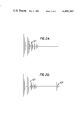
- FIG. 2A shows an oscilloscope trace of a first wall echo received from a structural member under test using the ultrasonic crack detection technique illustrated in FIG. 1 and indicative of a non-flooded condition of the structural member
- FIG. 2B shows an oscilloscope trace of time-spaced echoes received respectively from opposing walls of a structural member under test using the ultrasonic crack detection technique illustrated in FIG. 1 and indicative of a flooded condition of the structural member
- FIG. 3 is a plan view of an ultrasonic crack detection testing jig
- FIG. 4 is a front view of the jig of FIG. 3,
- FIG. 5 is an end view of the jig of FIG. 3, and
- FIG. 6 is a schematic diagram of an electronic monitoring and transmitting circuit of an ultrasonic inspection device.
- FIG. 1 shows a hollow structural member 1 partially filled with water 2 up to a level 3.
- a first ultrasonic transducer 4 for emitting short bursts of ultrasonic energy is positioned with respect to a wall face 5 of the member 1 such that the pulsed beam is normal thereto.
- the structural member 1 is an underwater structure so that the signals for operating the transducer 4 are received through an umbilical S from a vessel or other rig (not shown) situated on the water surface.
- the pulsed beam from the transducer 4 is directed into a non-flooded part of the member 1. Due to the poor transmission of ultrasound energy across the steel/air interface the beam is reflected at the face 5 without transmission so that the transducer 4 only receives echoes reflected from that wall face.
- a second similar ultrasonic transducer 6 is positioned such that its pulsed beam of ultrasound energy is directed to that part of the member which is flooded with water 2.
- two echoes are received by the transducer 6, the first one being a reflected echo from the wall face 5 and the other, with time delay, from the interior wall face 7 of an opposing wall of the structural member in the path of the pulsed ultrasound beam.
- the resulting echoes E1 and E2 received by the transducers 4 and 6 are illustrated as oscilloscope traces in FIGS. 2A and 2B respectively.
- the presence of the second echo E2 as shown in FIG. 2B may be taken to be an unambiguous indication that the member 1 is flooded.
- the reliability of the technique is maximal when all echoes received are accounted for. This can be accomplished by knowing the velocity of sound propagation in water and steel and the dimensions of the structural member to be inspected, from which the arrival times of expected echoes can be calculated. Any echoes which cannot be accounted for indicate some ambiguity in the procedure.
- a jig for carrying the ultrasonic transducer of the inspection device is shown in detail in FIGS. 3, 4 and 5.
- the jig comprises a support frame 8 having three spaced screw mounted control shafts 9.
- a bridge plate 10 is mounted for movement on the shafts 9, the bridge plate 10 being continuously urged into spaced relationship from the support frame 8 by means of coiled springs 11 surrounding each shaft 9.
- control shafts 9 Two of the control shafts 9 are provided with actuable control knobs 12 and 13, the control knob 12 being of circular configuration and the control knob 13 of triangular configuration for identification purposes.
- the remaining control shaft 9 is provided with a setting screw 14.
- the control knobs 12 and 13 and the setting screw 14 bear against the upper surface of the bridge plate 10 so that the spatial relationship between the bridge plate 10 and the support frame 8 can be varied by actuation thereof.
- the support frame 8 is provided on its underside with a bracket 15 having a magnetic foot 16 attached to each free end of the bracket 15.
- the free ends of the bracket 15 are angled obtusely to the central portion so that the feet 16 can be readily clamped partially around a tubular structural member under test.
- a further magnetic foot 17 is attached to the support frame 8, the positional relationship between the two magnetic feet 16 and the magnetic foot 17 being such that the mounting positions of the feet lie at the corners of an isoceles triangle and the mounting position of the foot 17 being at the apex of the isosceles triangle.
- the feet 16, 17 could be arranged on the support frame 8 each to lie in a flat plane thereby to enable the jig to be clamped to a flat surface.
- the feet 16, 17 could also be adjustably mounted in some suitable way so that the jig could be clamped to surfaces of varying shapes.
- the support frame 8 is provided with a handle 18 to enable an operator to manipulate the device into a test position.
- An ultrasonic transducer 19 is mounted to the bridge plate 10, the support frame 8 being provided with an aperture (not shown) to permit passage of ultrasonic sound to and from the transducer 19. Since the transducer is mounted to the bridge 10 it will be appreciated that its spacing from the structural member under test can be varied by actuation of control knobs 12 and 13 and setting screw 14. Furthermore the shafts 9 carrying the control knobs 12 and 13 are so arranged on the frame 8 that individual actuation of knobs 12 and 13 enables the bridge plate 10 to be moved in two orthogonal planes so that the ultrasound beam can be properly aligned with respect to the structural member under test thereby to optimise received echoes.
- the ultrasonic transducer 19 mounted to the jig as shown in FIGS. 3, 4 and 5, is capable of generating short bursts of ultrasound energy in the frequency range 0.1 and 5 MHz and may be adapted for underwater use if required.
- the transducer 19 is coupled to an electronic circuit as shown in FIG. 6, for monitoring received signals of reflected ultrasound from the transducer 19.
- the circuit comprises a preamplifier 20 provided with a gain control 21 for amplifying the received signals of reflected ultrasound from the transducer 19.
- the amplified signals are first fed to the inputs of a high gain amplifier 22 and a low gain amplifier 23 each respectively provided with gain controls 24 and 25.
- the amplifiers 22 and 23 are coupled to an oscilloscope 26 having two separate time base axes.
- the low gain amplifier 23 is used to monitor the first received reflected wall echo from a structural member under test and therefore requires less gain than the amplifier 22 used for monitoring the later time-spaced echo received from an opposing wall of the structural member under test and in the path of the ultrasonic pulsed beam.
- the outputs of the amplifiers 22 and 23 are also monitored by gated demodulators 27 and 28 respectively, the gates of these demodulators being indicated by reference numerals 29 and 30 respectively.
- Gate 30 of demodulator 28 is set on the lower trace of the oscilloscope 26 so that if the transducer 19 is properly aligned with respect to the immediately adjacent wall of a structural member under test, the resulting reflected echo falls between the delay limits or gate interval and amplitude limit imposed by the gate 30.
- the gate 30 is adjusted initially according to the known external dimensions of the structural member under test and the distance of the transducer from the wall of the structural member to which it is clamped.
- a visual alignment indicator 31 is coupled to the demodulator 30 and is thus activated by the gate 30 to display a green light when optimum alignment of the ultrasonic beam has been achieved.
- gate 29 of demodulator 27 is set on the upper trace of the oscilloscope 26 so as to activate a visual indicator 32 coupled thereto only if the later time-spaced echo falls within a delay limit and amplitude limit imposed by the gate 29 thus giving a visual indication of flooded conditions.
- This limit is again dependent on the external dimensions of the member under test and the separation of the ultrasonic transucer from the front wall of the structural member to which it is clamped.
- the flooded member indicator 32 displays a red light but with the arrangement shown the indicator 32 is invalid until the alignment indicator 31 shows green.
- the electronics for the ultrasonic inspection device as described may be positioned separately from the transducer jig.
- the transducer jig is connected to the electronics via an umbilical cable, the electronics being carried on board a ship or rig on the water surface.
- a diver operating the jig would have to rely on instructions from a distant source thus limiting somewhat the versatility of the device.
- the electronics in the transducer jig itself so that the diver can make the appropriate adjustments to optimise alignment of the transducer beam and to thereafter determine whether or not the member under test is flooded without reference to a remote controlling source.
Landscapes
- Physics & Mathematics (AREA)
- General Physics & Mathematics (AREA)
- Acoustics & Sound (AREA)
- Electromagnetism (AREA)
- Thermal Sciences (AREA)
- Fluid Mechanics (AREA)
- Investigating Or Analyzing Materials By The Use Of Ultrasonic Waves (AREA)
- Examining Or Testing Airtightness (AREA)
Abstract
Description
Claims (15)
Applications Claiming Priority (2)
| Application Number | Priority Date | Filing Date | Title |
|---|---|---|---|
| GB8L07L22 | 1981-03-06 | ||
| GB8107122A GB2094977B (en) | 1981-03-06 | 1981-03-06 | Detecting flooding of a structure |
Publications (1)
| Publication Number | Publication Date |
|---|---|
| US4445363A true US4445363A (en) | 1984-05-01 |
Family
ID=10520203
Family Applications (1)
| Application Number | Title | Priority Date | Filing Date |
|---|---|---|---|
| US06/349,984 Expired - Lifetime US4445363A (en) | 1981-03-06 | 1982-02-18 | Device for detecting flooding of a hollow structure |
Country Status (7)
| Country | Link |
|---|---|
| US (1) | US4445363A (en) |
| EP (1) | EP0060027B1 (en) |
| JP (1) | JPS57173738A (en) |
| CA (1) | CA1178364A (en) |
| DE (1) | DE3261794D1 (en) |
| GB (1) | GB2094977B (en) |
| NO (1) | NO156915C (en) |
Cited By (3)
| Publication number | Priority date | Publication date | Assignee | Title |
|---|---|---|---|---|
| JPH0566172A (en) * | 1991-06-25 | 1993-03-19 | Hitachi Ltd | Method and device for detecting leakage acoustically |
| US20120099398A1 (en) * | 2010-10-25 | 2012-04-26 | Lockheed Martin Corporation | Remote flooded member detection |
| NO344122B1 (en) * | 2018-09-20 | 2019-09-09 | 4Subsea As | Flooded Member Detection by means of ultrasound |
Families Citing this family (6)
| Publication number | Priority date | Publication date | Assignee | Title |
|---|---|---|---|---|
| GB2126342A (en) * | 1982-09-06 | 1984-03-21 | Innovative Tech Ltd | Liquid level detector |
| FR2590669B1 (en) * | 1985-11-27 | 1989-08-18 | Framatome Sa | METHOD AND DEVICE FOR DETECTING LOW-LEAKAGE LEAKAGE IN THE UNDERWATER PART OF THE WALL COATING OF A LIQUID TANK |
| FR2679938B1 (en) * | 1991-07-30 | 1993-12-10 | Brocvielle Jean Marie | ANTI-LOSS SECURITY INSTALLATION FOR BATHTUB. |
| DE10305003A1 (en) * | 2003-02-07 | 2004-08-19 | Jäger, Frank-Michael | Liquid detection unit, comprises an ultrasound transducer located on a container wall, with a piezo electric element that produces an ultrasound impulse |
| US8104341B2 (en) * | 2009-03-25 | 2012-01-31 | Schmitt Measurement Systems, Inc. | Ultrasonic liquid level monitoring system |
| CN110736522A (en) * | 2019-08-26 | 2020-01-31 | 广西电网有限责任公司电力科学研究院 | oil level detection method for sealed oil-filled equipment |
Citations (1)
| Publication number | Priority date | Publication date | Assignee | Title |
|---|---|---|---|---|
| US4242744A (en) * | 1977-09-27 | 1980-12-30 | Endress U. Hauser Gmbh U. Co. | Fixing of sonic transducer to a container |
Family Cites Families (3)
| Publication number | Priority date | Publication date | Assignee | Title |
|---|---|---|---|---|
| BE659053A (en) * | 1964-01-30 | |||
| US3585851A (en) * | 1969-11-24 | 1971-06-22 | Krautkramer Ultrasonics Inc | Method and apparatus for identifying defects with ultrasonic echoes |
| FR2325028A1 (en) * | 1975-09-18 | 1977-04-15 | Ultraflux | Level detector for liquid in reservoir - uses transmit-receive pulsed acoustic probe in contact with outside wall to monitor level of reflection of acoustic pulses |
-
1981
- 1981-03-06 GB GB8107122A patent/GB2094977B/en not_active Expired
-
1982
- 1982-02-09 DE DE8282300632T patent/DE3261794D1/en not_active Expired
- 1982-02-09 EP EP82300632A patent/EP0060027B1/en not_active Expired
- 1982-02-18 US US06/349,984 patent/US4445363A/en not_active Expired - Lifetime
- 1982-02-23 CA CA000396833A patent/CA1178364A/en not_active Expired
- 1982-03-04 JP JP57034520A patent/JPS57173738A/en active Pending
- 1982-03-05 NO NO820689A patent/NO156915C/en unknown
Patent Citations (1)
| Publication number | Priority date | Publication date | Assignee | Title |
|---|---|---|---|---|
| US4242744A (en) * | 1977-09-27 | 1980-12-30 | Endress U. Hauser Gmbh U. Co. | Fixing of sonic transducer to a container |
Cited By (12)
| Publication number | Priority date | Publication date | Assignee | Title |
|---|---|---|---|---|
| JPH0566172A (en) * | 1991-06-25 | 1993-03-19 | Hitachi Ltd | Method and device for detecting leakage acoustically |
| US20120099398A1 (en) * | 2010-10-25 | 2012-04-26 | Lockheed Martin Corporation | Remote flooded member detection |
| WO2012061069A2 (en) | 2010-10-25 | 2012-05-10 | Lockheed Martin Corporation | Remote flooded member detection |
| WO2012061069A3 (en) * | 2010-10-25 | 2013-10-03 | Lockheed Martin Corporation | Remote flooded member detection |
| CN103492946A (en) * | 2010-10-25 | 2014-01-01 | 洛克希德马丁公司 | Remote flooded member detection |
| US8917576B2 (en) * | 2010-10-25 | 2014-12-23 | Lockheed Martin Corporation | Remote flooded member detection |
| EP2633336A4 (en) * | 2010-10-25 | 2015-01-21 | Lockheed Corp | Remote flooded member detection |
| AU2011323815B2 (en) * | 2010-10-25 | 2015-04-23 | Lockheed Martin Corporation | Remote flooded member detection |
| CN103492946B (en) * | 2010-10-25 | 2016-11-09 | 洛克希德马丁公司 | Remotely water inlet component detection |
| NO344122B1 (en) * | 2018-09-20 | 2019-09-09 | 4Subsea As | Flooded Member Detection by means of ultrasound |
| WO2020057994A1 (en) | 2018-09-20 | 2020-03-26 | 4Subsea As | Flooded member detection by means of ultrasound |
| US11609209B2 (en) * | 2018-09-20 | 2023-03-21 | 4Subsea As | Flooded member detection by means of ultrasound |
Also Published As
| Publication number | Publication date |
|---|---|
| NO156915C (en) | 1987-12-16 |
| DE3261794D1 (en) | 1985-02-21 |
| NO156915B (en) | 1987-09-07 |
| CA1178364A (en) | 1984-11-20 |
| EP0060027B1 (en) | 1985-01-09 |
| NO820689L (en) | 1982-09-07 |
| JPS57173738A (en) | 1982-10-26 |
| EP0060027A1 (en) | 1982-09-15 |
| GB2094977B (en) | 1984-08-08 |
| GB2094977A (en) | 1982-09-22 |
Similar Documents
| Publication | Publication Date | Title |
|---|---|---|
| US4457178A (en) | Process and apparatus for testing of rails by ultrasound | |
| US4658649A (en) | Ultrasonic method and device for detecting and measuring defects in metal media | |
| US3427866A (en) | Ultrasonic thickness gauge and flow detector | |
| US4445363A (en) | Device for detecting flooding of a hollow structure | |
| CN108562647A (en) | The polyethylene pipe hot melt banjo fixing butt jointing supersonic detection device and method that PA-TOFD is combined | |
| JPH0324454A (en) | Ultrasonic flaw detecting method | |
| US20140216160A1 (en) | Device for the non-destructive inspection of a test object by means of ultrasound, method for operating such a device and method for the non-destructive inspection of a test object by means of ultrasound | |
| CA2012374C (en) | Ultrasonic crack sizing method | |
| JP3497984B2 (en) | Ultrasonic flaw detector | |
| CN114487120B (en) | A method for measuring the height of internal defects in fillet welds | |
| CA1315869C (en) | Contact ultrasonic transducer head | |
| JP3281878B2 (en) | Ultrasonic flaw detection method and apparatus | |
| JPH0850177A (en) | Ultrasonic distance measuring device | |
| JPS63263467A (en) | Ultrasonic flaw detecting method | |
| JP4112526B2 (en) | Ultrasonic flaw detection method and apparatus | |
| GB2292610A (en) | Crack detection in a sheet of material around a fastener hole | |
| US4182154A (en) | Initializing ultrasonic test equipment with a particular reference element | |
| SU1705735A1 (en) | Method of ultrasonic testing of articles | |
| CN209264634U (en) | An Ultrasonic Scattering Inspection Device for Electron Beam Welding Parts | |
| JPH08261992A (en) | Ultrasonic flaw detector | |
| US3395572A (en) | Apparatus for ultrasonic detection and display of location of material defects | |
| RU2000117832A (en) | METHOD FOR DETECTING PLANE DIFFERENCES IN THICK-WALLED PRODUCTS BY THE ULTRASONIC METHOD | |
| JPH08220079A (en) | Ultrasonic probe | |
| CN118258890A (en) | A weld detection method based on ultrasonic automatic full coverage detection device | |
| JPH0258589B2 (en) |
Legal Events
| Date | Code | Title | Description |
|---|---|---|---|
| AS | Assignment |
Owner name: BRITISH GAS CORPORATION; RIVERMILL HOUSE, 152 GROS Free format text: ASSIGNMENT OF ASSIGNORS INTEREST.;ASSIGNORS:BENNETT, ALAN;BROWN, DEREK;REEL/FRAME:004002/0713 Effective date: 19820607 Owner name: BRITISH GAS CORPORATION; RIVERMILL HOUSE, 152 GROS Free format text: ASSIGNMENT OF ASSIGNORS INTEREST;ASSIGNORS:BENNETT, ALAN;BROWN, DEREK;REEL/FRAME:004002/0713 Effective date: 19820607 |
|
| STCF | Information on status: patent grant |
Free format text: PATENTED CASE |
|
| FEPP | Fee payment procedure |
Free format text: PAYOR NUMBER ASSIGNED (ORIGINAL EVENT CODE: ASPN); ENTITY STATUS OF PATENT OWNER: LARGE ENTITY |
|
| FPAY | Fee payment |
Year of fee payment: 4 |
|
| AS | Assignment |
Owner name: BRITISH GAS PLC, RIVERMILL HOUSE 152 GROSVENOR ROA Free format text: ASSIGNMENT OF ASSIGNORS INTEREST.;ASSIGNOR:BRITISH GAS CORPORATION;REEL/FRAME:004859/0891 Effective date: 19870512 Owner name: BRITISH GAS PLC, ENGLAND Free format text: ASSIGNMENT OF ASSIGNORS INTEREST;ASSIGNOR:BRITISH GAS CORPORATION;REEL/FRAME:004859/0891 Effective date: 19870512 |
|
| FPAY | Fee payment |
Year of fee payment: 8 |
|
| FPAY | Fee payment |
Year of fee payment: 12 |