US4441778A - Patchcord connector - Google Patents
Patchcord connector Download PDFInfo
- Publication number
- US4441778A US4441778A US06/309,900 US30990081A US4441778A US 4441778 A US4441778 A US 4441778A US 30990081 A US30990081 A US 30990081A US 4441778 A US4441778 A US 4441778A
- Authority
- US
- United States
- Prior art keywords
- conductor
- housing
- termination
- piercing
- insulated
- Prior art date
- Legal status (The legal status is an assumption and is not a legal conclusion. Google has not performed a legal analysis and makes no representation as to the accuracy of the status listed.)
- Expired - Fee Related
Links
Images


Classifications
-
- H—ELECTRICITY
- H01—ELECTRIC ELEMENTS
- H01R—ELECTRICALLY-CONDUCTIVE CONNECTIONS; STRUCTURAL ASSOCIATIONS OF A PLURALITY OF MUTUALLY-INSULATED ELECTRICAL CONNECTING ELEMENTS; COUPLING DEVICES; CURRENT COLLECTORS
- H01R4/00—Electrically-conductive connections between two or more conductive members in direct contact, i.e. touching one another; Means for effecting or maintaining such contact; Electrically-conductive connections having two or more spaced connecting locations for conductors and using contact members penetrating insulation
- H01R4/24—Connections using contact members penetrating or cutting insulation or cable strands
- H01R4/2416—Connections using contact members penetrating or cutting insulation or cable strands the contact members having insulation-cutting edges, e.g. of tuning fork type
- H01R4/242—Connections using contact members penetrating or cutting insulation or cable strands the contact members having insulation-cutting edges, e.g. of tuning fork type the contact members being plates having a single slot
- H01R4/2425—Flat plates, e.g. multi-layered flat plates
- H01R4/2429—Flat plates, e.g. multi-layered flat plates mounted in an insulating base
-
- H—ELECTRICITY
- H01—ELECTRIC ELEMENTS
- H01R—ELECTRICALLY-CONDUCTIVE CONNECTIONS; STRUCTURAL ASSOCIATIONS OF A PLURALITY OF MUTUALLY-INSULATED ELECTRICAL CONNECTING ELEMENTS; COUPLING DEVICES; CURRENT COLLECTORS
- H01R13/00—Details of coupling devices of the kinds covered by groups H01R12/70 or H01R24/00 - H01R33/00
- H01R13/58—Means for relieving strain on wire connection, e.g. cord grip, for avoiding loosening of connections between wires and terminals within a coupling device terminating a cable
Definitions
- This invention relates generally to electrical connectors and more particularly to patchcord connectors for terminating one or more insulated conductors and electrically interconnecting the conductors to a terminal board or other electrical component.
- the present invention relates to an improved patchcord connector for multi-conductor electrical cables having means for independently terminating individual conductors and also including separate strain relief means for each conductor and a strain relief for the entire cable.
- Patchcords designed for this purpose are used, for example, in telephone exchanges and telephone central offices. They are also used in office and apartment buildings where large numbers of incoming lines must be interconnected with inside telephone lines.
- patchcords are conveniently terminated at one or both ends with connectors which must exhibit a high degree of reliability, particularly in view of the numerous mating cycles encountered in their use. Accordingly, patchcord connectors should be ruggedly constructed and designed with adequate strain relief to prevent disengagement of the conductors should the patchcord be pulled or tugged during mating of the connector.
- the object of the present invention to provide an improved patchcord connector which overcomes the above-mentioned deficiencies of the prior art.
- the patchcord connectors described herein are of simple, rugged construction and are readily pre-assembled for later use in the field.
- the connectors are each capable of independently terminating a number of separate insulated conductors, and they include separate strain relief means for each individual conductor as well as for the multi-conductor patchcord itself.
- the present invention is directed to a patchcord connector for terminating at least one insulated conductor.
- the connector includes a housing having at least one elongated pocket with an access opening in communication with the exterior of the housing.
- the pocket and the access opening are dimensioned to accept the insulated conductor.
- the connector also includes at least one contact element with a termination portion disposed within the elongated pocket.
- the termination portion includes means for piercing the insulation of the insulated conductor.
- the present patchcord connector has means associated with the housing for driving the insulated conductor into the piercing means, to establish electrical connection between the contact element and the conductor.
- the driving means is operable from a point outside of the connector housing.
- the present patchcord connector consists of first and second interlockable body members. At least one of the body members carries an elongated groove along the surface adjoining the two members when they are interlocked to define the elongated pocket.
- the interlockable body members may be joined along a corresponding edge by integrally formed unitary hinge.
- the contact termination portion employed in the present invention optimally includes positioning means in the form of an aperture in communication with the piercing means. This aperture which is large enough to freely accept the insulated conductor is positioned for locating the insulated conductor adjacent the piercing means.
- the driving means employed in the present invention may be mounted in an aperture in the connector housing overlying the piercing means.
- Typical driving means include a push button mounted for movement between a pre-termination position and a termination position. With the push button in its pre-termination position, the driving means is separated from the insulated conductor. Movement of the push button to its termination position will move the driving means into abutment with the insulated conductor into electrical connection with the contact element.
- the push button when in its pre-termination position, may be frangibly mounted in the aperture overlying the piercing means. Alternatively, it may be hinged to an edge of the housing aperture.
- Strain relief means for the insulated conductor is provided by positioning a relief recess coincident with the piercing means to permit a portion of the conductor engaged by the driving means to be depressed thereinto.
- Enhanced strain relief is obtained by restraining the conductor in the space between a projecting edge adjacent the relief recess and the driving means, in its depressed position.
- the piercing means and the driving means cooperate in terminating the insulated conductor.
- the piercing means is generally planar and the driving means is mounted for face-to-face movement with respect thereto.
- the driving means may include portions with generally parallel planar surfaces defining a slot so that the driving means may move with these parallel portions astride the piercing means.
- the patchcord connector will include means for independently driving each insulated conductor into the piercing means of a respective contact element termination portion.
- the patchcord connector contain a separate strain relief for the cable itself.
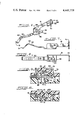
- FIG. 1 is a bottom plan view of a fully assembled patchcord connector constructed in accordance with the present invention
- FIG. 2 is a top plan view of a patchcord connector according to the present invention, in an open, unassembled position and illustrating the interior construction of the connector housing;
- FIG. 3 is an enlarged and elevation view of the connector of FIG. 2;
- FIG. 4 is an enlarged, cross-sectional view taken along line 4--4 of FIG. 2;
- FIG. 5 is an enlarged, cross-sectional view of driving means utilized in the invention.
- FIG. 6 is an enlarged perspective view of a contact element utilized in the present patchcord connector
- FIG. 7 is a front elevation view of the contact of FIG. 6;
- FIG. 8 is a top plan view of the contact of FIGS. 6 and 7;
- FIG. 9 is an enlarged fragmentary elevation view of a push button of the present invention in its pre-termination position with driving means separated from an insulated conductor positioned for termination;
- FIG. 10 is an enlarged fragmentary elevation view of a push button of the present invention in its termination position with the conductor in electrical connection with the contact element and the driving means abutting the insulated connector;
- FIG. 11 is a cross-sectional view taken along line 11--11 of FIG. 9;
- FIG. 12 is a cross-sectional view taken along line 12--12 of FIG. 10;
- FIG. 13 is an enlarged cross-sectional view taken along line 13--13 of FIG. 1;
- FIG. 14 is a fragmentary cross-sectional view of the integrally formed unitary hinge of the present invention taken along line 14--14 of FIG. 2;
- FIG. 15 is a cross-sectional view of the hinge of FIG. 14 with first and second interlockable body members of the present invention in closed, interlocked position.
- a patchcord connector 10 is shown, having a plurality of insulated conductors 12 terminated therein.
- actual termination in an individual contact is shown for only one of the conductors 12 (FIG. 2).
- the insulated conductors 12 together comprise a multiple conductor cable 14, which is illustrated emerging from the rear end 16 of the connector housing 18.
- the connector housing may be formed from any suitable dielectric material. Preferably, it will be constructed from a generally rigid plastic material using conventional molding techniques. Use of a clear material will enhance the practical value of the present invention by facilitating inspection of the internal condition of the connector, including conductors and contacts.
- the housing 18 includes first and second interlockable body members in the form of base 20 and cover 22.
- Base 20 and cover 22 may be interlocked by means of cover latches 26 which engage in latch acceptance apertures 28.
- Base 20 and cover 22 are hingedly secured together by integral living hinge 24. Hinge 24 is illustrated in its open and closed positions in FIGS. 14 and 15 respectively.
- Base member 20 includes plug portion 30 with leg members 34 corresponding in number to the number of conductors 12 to be terminated within the connector 10.
- Each leg member 34 projects outwardly from the front 36 of the housing 18 for engagement with mating receptacles on a terminal or patch board.
- the bottom 20, as illustrated, includes molding access holes 21 which may accept test probes for checking electrical continuity within the connector.
- the bottom portion 20 of the housing 18 includes recess 38 (FIG. 4) for positively centering cable 14.
- Recess 38 extends from end 16 to radiating recess 40 in which the individual insulated conductors 12 may be separated for termination.
- Radiating recess 40 communicates with access slots 41 and elongated channels 42 which extend to the terminal ends 35 of their respective plug portion leg members 34. Assembly of the connector by joining cover 22 to base 20 along their respective opposing faces 25 and 23 will enclose access slots 41 and elongated channels 42 to transform them respectively to access openings in communication with the exterior of housing 18 and enclosed recesses or elongated pockets. These pockets may be filled with silicone grease during assembly of the connector 10 to obtain enhanced environmental sealing.
- Channels 42 include a wire receiving portion 44 and a contact element receiving portion 46.
- Contact elements 48 which are best illustrated in FIGS. 6-8, are designed to be press-fitted within the contact receiving portion 46 of elongated channels 42.
- Each contact element 48 includes an active portion 50 for positioning within the mating channel 52 of a plug portion leg member 34.
- Active portion 50 of contact 48 includes a bowed section 53 for engaging the active portion of a corresponding contact member mounted in a terminal or patching board.
- the active contact portion 50 also includes an end 51 designed to abut a shoulder member 37 disposed adjacent the end of mating channel 52 of plug leg member 34 to prevent the contact element tip from being cracked during insertion of the contact 10 into a terminal board.
- Contact elements 48 also include a planar intermediate portion 54, elongated aperture 56 and forward edge 58.
- Contact elements 48 are preferably press-fitted within contact element receiving portions 46 of elongated channels 42 and held in proper orientation within the channels by means of integral elongated lugs 60 and integral channel stop 62. This is best illustrated in FIGS. 2 and 4 where integral elongated lug 60 is shown in engagement with contact elongated aperture 56 and contact leading edge 58 is shown in abutment with channel stop 62.
- Contact elements 48 include arm portions 61 oriented generally perpendicularly to intermediate portions 54. Arm portions 61 carry termination portions 63 which in turn lie in a plane generally perpendicular to both arm portions 61 and intermediate portions 54.
- An open keyhole aperture including generally circular opening 64 and communicating slot 66 is located in termination portion 63 of each contact element 48. Opening 64 acts as a positioning means for positioning an insulated conductor 12 adjacent slot 66 which is designed to act as an insulation piercing means, as discussed further below. Opening 64 must be of a size sufficient to accommodate insulated conductor 12.
- the insulaton piercing means includes slot 66 defined by legs 68 with edges 70 spaced at a distance less than the diameter of the conductor portion (not shown) of insulated conductors 12. Edges 70 include means for cutting through the insulation of insulated conductor 12 and biting into the conductive portion to establish electrical contact.
- the present patchcord connector 10 may be readily formed or manufactured and pre-assembled, prior to use in the field for terminating insulated conductors 12.
- the structural layout of the connector housing 14 in a single piece facilitates injection molding without side movement of the mold--all molding is done by up and down movement.
- Pre-assembly then entails the press-fitting of contact elements 48 in the appropriate locations in channels 42 and the interlocking of housing top 22 to bottom 20 by means of latches 26 and catches 28, as described earlier.
- these pre-assembled connectors When these pre-assembled connectors are received in the field, they then may be used to terminate individual conductors 12 of a multiple conductor cable 14, through the cooperation of termination portions 63 discussed above, and driving means 72, which will be described below.
- Driving means 72 are mounted in apertures 74 of cover 22. In the pre-assembled patchcord connector, these apertures overlie termination portions 63. Driving means 72 includes operating means in the form of push button 76 which is disposed within aperture 74 for operation from a point outside of housing 18.
- Push button 76 is mounted in aperture 74 for movement between the pre-termination position depicted in FIG. 9 and the termination position depicted in FIG. 10. In its pre-terminaton position, push button 72 may be fixed within the aperture by a living hinge or by other conventional means. In the preferred embodiment illustrated in the present Figures, push button 74 is frangibly mounted in aperture 74 by means of break away portions 78.
- Driving means 72 includes projecting portion 80 which is positioned in the assembled connector for face-to-face movement with respect to termination portions 63 as push button 76 moves from its pre-termination (FIG. 9) to its termination position (FIG. 10).
- Projecting portion 80 includes generally planar parallel surfaces 82 defining a slot 84 of width slightly greater than the thickness of termination portions 63. As push button 76 is moved from its pre-termination position to its termination position, parallel surfaces 82 will move astride termination portions 63.
- driving means 72 provides positive strain relief for the terminated conductor. This strain relief is accomplished through the cooperation of relief recess 88 which is coincident with contact piercing means 62. As the projecting portion 80 of driving means 72 drives insulated conductor 12 into slot 66, it will depress a portion 90 of conductor 12 into relief recess 88 to obtain a measure of strain relief. In addition, bevelled faces 92A and 92B of nose portions 86A and 86B will further constrain conductor portion 90 against respective projecting edges 94A and 94B of relief recess 88 to obtain a more positive strain relief.
- a positive indication that a particular conductor has been fully terminated and that strain relief of that conductor has been accomplished is provided by push button locking means consisting of latches 96 and 98 with respective bevelled faces 100 and 102 and respective mating lips 104 and 106.
- latch 98 which is integral with elongated channel 42, is far less massive and therefore more flexible than latch 96.
- push button 76 When push button 76 reaches its termination position, neck 110 snaps back as mating lips 104 and 106 come into abutment. This snapping action generally results in an audible "click” indicating that push button 76 is locked in its termination position and that electrical connection and strain relief have been accomplished. Push button 76 may be released and removed, if necessary, by inserting a tool to move latch 98 out of the way.
- Patchcord connector 10 includes a cable strain relief 112 to limit relative movement between multiconductor cable 14 and the connector housing 18.
- the strain relief 112 which is depicted in its closed position in FIG. 13, is attached to the neck portion 19 of housing bottom 20 by an integral strap hinge 113.
- Strain relief 112 includes two latches 114 along strain relief inner edge 116 and a third latch 120 along the opposite edge 122 of the strain relief 112.
- Centered on the face 124 of strain relief 112 is a bifurcated jaw 126 with longitudinal groove 128 of generally triangular cross-section. Latches 114 and 120 are flexible and separated by a distance corresponding to the width of neck portion 19.
- Opposite edges 19A and 19B of neck portion 19 carry catches 132 and catch 134 for mating with corresponding latches 114 and 120.
- Cable 14 is fixed in place relative to connector 10 by positioning it in centering recess 38 and then hooking latches 114 with respective catches 132.
- Latch 120 of strain relief 112 is then forced down against leading bevelled edge 136 of catch 134 causing catch 120 to flex out and ride along the outer surface of catch 134 finally snapping back to its original position to lock strain relief 112 in place.
- bifurcated jaw 126 will cooperate with centering recess 38 to limit the relative movement between cable 14 and connector 10.
- the present patchcord connector may be used to terminate the individual insulated conductors of a multiple conductor cable as follows:
- the multiple conductor cable 14 is first stripped in order to expose the separate insulated conductors contained therein.
- the cable 14 is then positioned in centering recess 38 and fixed in place by cable strain relief 112.
- the individual insulated conductors 12 are inserted through access slots 41 and into the pockets formed from elongated channels 42.
- a positive stop to insure that a sufficient length of insulated conductor 14 is inserted is provided by the rearward surface 111 of latch 98.
- the present invention provides for the straightforward termination of insulated conductors in a patchcord connector. Independent termination of individual conductors may be accomplished by this invention to obtain positive termination and strain relief of each individual conductor. Since termination means are stationary within the connector, the criticality of the positioning of the termination means and the need for reinforcement are reduced or eliminated. Finally, separate strain relief is provided for the multiconductor cable and for each individual insulated conductor.
Landscapes
- Multi-Conductor Connections (AREA)
Abstract
Description
Claims (15)
Priority Applications (1)
| Application Number | Priority Date | Filing Date | Title |
|---|---|---|---|
| US06/309,900 US4441778A (en) | 1979-11-13 | 1981-10-09 | Patchcord connector |
Applications Claiming Priority (2)
| Application Number | Priority Date | Filing Date | Title |
|---|---|---|---|
| US9340179A | 1979-11-13 | 1979-11-13 | |
| US06/309,900 US4441778A (en) | 1979-11-13 | 1981-10-09 | Patchcord connector |
Related Parent Applications (1)
| Application Number | Title | Priority Date | Filing Date |
|---|---|---|---|
| US9340179A Continuation | 1979-11-13 | 1979-11-13 |
Publications (1)
| Publication Number | Publication Date |
|---|---|
| US4441778A true US4441778A (en) | 1984-04-10 |
Family
ID=26787492
Family Applications (1)
| Application Number | Title | Priority Date | Filing Date |
|---|---|---|---|
| US06/309,900 Expired - Fee Related US4441778A (en) | 1979-11-13 | 1981-10-09 | Patchcord connector |
Country Status (1)
| Country | Link |
|---|---|
| US (1) | US4441778A (en) |
Cited By (14)
| Publication number | Priority date | Publication date | Assignee | Title |
|---|---|---|---|---|
| US4579404A (en) * | 1983-09-26 | 1986-04-01 | Amp Incorporated | Conductor-terminated card edge connector |
| US4602831A (en) * | 1983-09-26 | 1986-07-29 | Amp Incorporated | Electrical connector and method of making same |
| US4648674A (en) * | 1985-07-01 | 1987-03-10 | Allied Corporation | In-line fuseholder |
| US4659168A (en) * | 1984-09-06 | 1987-04-21 | Burndy Corporation | Electrical connector |
| US4682840A (en) * | 1983-09-26 | 1987-07-28 | Amp Incorporated | Electrical connection and method of making same |
| US4693539A (en) * | 1983-12-27 | 1987-09-15 | Amp Incorporated | Ribbon coax cable connector |
| US4734048A (en) * | 1985-07-10 | 1988-03-29 | Siemens Aktiengesellschaft | Distributor housing for communication cables |
| US4826443A (en) * | 1982-11-17 | 1989-05-02 | Amp Incorporated | Contact subassembly for an electrical connector and method of making same |
| EP0311769A3 (en) * | 1987-10-13 | 1990-05-02 | Grote & Hartmann GmbH & Co. KG | Miniaturized spring contact plug |
| EP0431837A3 (en) * | 1989-12-06 | 1992-01-15 | Molex Incorporated | Splice block for security system switch |
| US5464352A (en) * | 1992-11-13 | 1995-11-07 | Alcatel Components Limited | Electrical connector assembly |
| AU675528B2 (en) * | 1994-06-06 | 1997-02-06 | Krone Gmbh | Test plug |
| US5601447A (en) * | 1995-06-28 | 1997-02-11 | Reed; Carl G. | Patch cord assembly |
| US6370769B1 (en) | 1999-10-27 | 2002-04-16 | Avaya Technology Corp. | Automated assembly of connector to cable having twisted wire pairs |
Citations (10)
| Publication number | Priority date | Publication date | Assignee | Title |
|---|---|---|---|---|
| US2359541A (en) * | 1941-07-29 | 1944-10-03 | Int Standard Electric Corp | Insulated wire connector |
| US2584476A (en) * | 1949-05-17 | 1952-02-05 | Angelo R Liaci | Electric terminal and conductor mounting |
| US3388367A (en) * | 1966-06-20 | 1968-06-11 | Hughes Aircraft Co | Electrical connector for either flat or round conductors |
| US3868161A (en) * | 1973-10-01 | 1975-02-25 | Amp Inc | Electrical component |
| US3899236A (en) * | 1974-06-24 | 1975-08-12 | Amerace Corp | Electrical connector |
| US3910672A (en) * | 1974-06-03 | 1975-10-07 | Amp Inc | Replacement cover for electrical wiring devices |
| US4138184A (en) * | 1978-03-06 | 1979-02-06 | Amp Incorporated | Terminating means for a multi-wire cable |
| US4160575A (en) * | 1978-02-24 | 1979-07-10 | Vari-Tronics Co. | Telephone cord connector |
| US4165145A (en) * | 1976-04-01 | 1979-08-21 | Trw Inc. | Ribbon connector constructions |
| DE2906031A1 (en) * | 1978-02-20 | 1979-08-23 | Bunker Ramo | SELF-CONTACTING ELECTRICAL CONNECTION DEVICE |
-
1981
- 1981-10-09 US US06/309,900 patent/US4441778A/en not_active Expired - Fee Related
Patent Citations (10)
| Publication number | Priority date | Publication date | Assignee | Title |
|---|---|---|---|---|
| US2359541A (en) * | 1941-07-29 | 1944-10-03 | Int Standard Electric Corp | Insulated wire connector |
| US2584476A (en) * | 1949-05-17 | 1952-02-05 | Angelo R Liaci | Electric terminal and conductor mounting |
| US3388367A (en) * | 1966-06-20 | 1968-06-11 | Hughes Aircraft Co | Electrical connector for either flat or round conductors |
| US3868161A (en) * | 1973-10-01 | 1975-02-25 | Amp Inc | Electrical component |
| US3910672A (en) * | 1974-06-03 | 1975-10-07 | Amp Inc | Replacement cover for electrical wiring devices |
| US3899236A (en) * | 1974-06-24 | 1975-08-12 | Amerace Corp | Electrical connector |
| US4165145A (en) * | 1976-04-01 | 1979-08-21 | Trw Inc. | Ribbon connector constructions |
| DE2906031A1 (en) * | 1978-02-20 | 1979-08-23 | Bunker Ramo | SELF-CONTACTING ELECTRICAL CONNECTION DEVICE |
| US4160575A (en) * | 1978-02-24 | 1979-07-10 | Vari-Tronics Co. | Telephone cord connector |
| US4138184A (en) * | 1978-03-06 | 1979-02-06 | Amp Incorporated | Terminating means for a multi-wire cable |
Cited By (14)
| Publication number | Priority date | Publication date | Assignee | Title |
|---|---|---|---|---|
| US4826443A (en) * | 1982-11-17 | 1989-05-02 | Amp Incorporated | Contact subassembly for an electrical connector and method of making same |
| US4602831A (en) * | 1983-09-26 | 1986-07-29 | Amp Incorporated | Electrical connector and method of making same |
| US4682840A (en) * | 1983-09-26 | 1987-07-28 | Amp Incorporated | Electrical connection and method of making same |
| US4579404A (en) * | 1983-09-26 | 1986-04-01 | Amp Incorporated | Conductor-terminated card edge connector |
| US4693539A (en) * | 1983-12-27 | 1987-09-15 | Amp Incorporated | Ribbon coax cable connector |
| US4659168A (en) * | 1984-09-06 | 1987-04-21 | Burndy Corporation | Electrical connector |
| US4648674A (en) * | 1985-07-01 | 1987-03-10 | Allied Corporation | In-line fuseholder |
| US4734048A (en) * | 1985-07-10 | 1988-03-29 | Siemens Aktiengesellschaft | Distributor housing for communication cables |
| EP0311769A3 (en) * | 1987-10-13 | 1990-05-02 | Grote & Hartmann GmbH & Co. KG | Miniaturized spring contact plug |
| EP0431837A3 (en) * | 1989-12-06 | 1992-01-15 | Molex Incorporated | Splice block for security system switch |
| US5464352A (en) * | 1992-11-13 | 1995-11-07 | Alcatel Components Limited | Electrical connector assembly |
| AU675528B2 (en) * | 1994-06-06 | 1997-02-06 | Krone Gmbh | Test plug |
| US5601447A (en) * | 1995-06-28 | 1997-02-11 | Reed; Carl G. | Patch cord assembly |
| US6370769B1 (en) | 1999-10-27 | 2002-04-16 | Avaya Technology Corp. | Automated assembly of connector to cable having twisted wire pairs |
Similar Documents
| Publication | Publication Date | Title |
|---|---|---|
| US5460545A (en) | Patch connector | |
| US4195898A (en) | Patchcord connector | |
| US4441778A (en) | Patchcord connector | |
| KR930003562B1 (en) | Sealed Data Connector | |
| US6454611B1 (en) | Surface mountable electrical connector system | |
| US4697862A (en) | Insulation displacement coaxial cable termination and method | |
| US6328592B1 (en) | Electrical connector with cable clamping means | |
| US3835445A (en) | Electrical connecting devices for terminating cords and methods of assembling the devices to cords | |
| US4040699A (en) | Female connector and escutcheon plate combined therewith for telephone equipment | |
| US6565388B1 (en) | Shielded cable connector | |
| US4701138A (en) | Solderless electrical connector | |
| EP0292528A1 (en) | Shielded electrical connector having an insulating cover on the shielding member | |
| MXPA97004233A (en) | Electrical connector with deca engrapement media | |
| US4842549A (en) | Dual diameter cable strain relief | |
| CA1236539A (en) | Electrical plug assembly with cable guiding member | |
| GB2232827A (en) | Electrical connector system for coaxial cable | |
| GB1499926A (en) | Contact device for a flat cable | |
| CA1193684A (en) | Connector for shielded flat cable | |
| US4160574A (en) | Connector for flat wire cables having improved contacts and integral strain relief means | |
| US4106838A (en) | Stackable flat cable connector and contact therefor | |
| US6231390B1 (en) | Connector for use in portable phone | |
| JPH01501825A (en) | electrical connectors | |
| EP0018160B1 (en) | Electrical connector for terminating flat, multi-conductor electrical cable | |
| KR20020046965A (en) | Electrical connector assembly for flat flexible circuitry | |
| JPS63207061A (en) | Connector for telephone cable |
Legal Events
| Date | Code | Title | Description |
|---|---|---|---|
| AS | Assignment |
Owner name: ALLIED CORPORATION A CORP. OF NY, NEW JERSEY Free format text: ASSIGNMENT OF ASSIGNORS INTEREST;ASSIGNOR:BUNKER RAMO CORPORATION A CORP. OF DE;REEL/FRAME:004149/0365 Effective date: 19820922 Owner name: ALLIED CORPORATION COLUMBIA ROAD AND PARK AVENUE, Free format text: ASSIGNMENT OF ASSIGNORS INTEREST.;ASSIGNOR:BUNKER RAMO CORPORATION A CORP. OF DE;REEL/FRAME:004149/0365 Effective date: 19820922 |
|
| FEPP | Fee payment procedure |
Free format text: PAYOR NUMBER ASSIGNED (ORIGINAL EVENT CODE: ASPN); ENTITY STATUS OF PATENT OWNER: LARGE ENTITY |
|
| AS | Assignment |
Owner name: CANADIAN IMPERIAL BANK OF COMMERCE, NEW YORK AGENC Free format text: SECURITY INTEREST;ASSIGNOR:AMPHENOL CORPORATION;REEL/FRAME:004879/0030 Effective date: 19870515 |
|
| AS | Assignment |
Owner name: AMPHENOL CORPORATION, LISLE, ILLINOIS A CORP. OF D Free format text: ASSIGNMENT OF ASSIGNORS INTEREST.;ASSIGNOR:ALLIED CORPORATION, A CORP. OF NY;REEL/FRAME:004844/0850 Effective date: 19870602 Owner name: AMPHENOL CORPORATION, A CORP. OF DE, ILLINOIS Free format text: ASSIGNMENT OF ASSIGNORS INTEREST;ASSIGNOR:ALLIED CORPORATION, A CORP. OF NY;REEL/FRAME:004844/0850 Effective date: 19870602 |
|
| MAFP | Maintenance fee payment |
Free format text: PAYMENT OF MAINTENANCE FEE, 4TH YEAR, PL 96-517 (ORIGINAL EVENT CODE: M170); ENTITY STATUS OF PATENT OWNER: LARGE ENTITY Year of fee payment: 4 |
|
| FEPP | Fee payment procedure |
Free format text: PAYOR NUMBER ASSIGNED (ORIGINAL EVENT CODE: ASPN); ENTITY STATUS OF PATENT OWNER: LARGE ENTITY Free format text: PAYER NUMBER DE-ASSIGNED (ORIGINAL EVENT CODE: RMPN); ENTITY STATUS OF PATENT OWNER: LARGE ENTITY |
|
| MAFP | Maintenance fee payment |
Free format text: PAYMENT OF MAINTENANCE FEE, 8TH YEAR, PL 96-517 (ORIGINAL EVENT CODE: M171); ENTITY STATUS OF PATENT OWNER: LARGE ENTITY Year of fee payment: 8 |
|
| AS | Assignment |
Owner name: BANKERS TRUST COMPANY Free format text: SECURITY INTEREST;ASSIGNORS:AMPHENOL INTERCONNECT PRODUCTS CORPORATION;AMPHENOL INTERNATIONAL LTD.;PYLE INC.;AND OTHERS;REEL/FRAME:006031/0651 Effective date: 19911118 |
|
| AS | Assignment |
Owner name: AMPHENOL CORPORATION A CORP. OF DELAWARE Free format text: RELEASED BY SECURED PARTY;ASSIGNOR:CANADIAN IMPERIAL BANK OF COMMERCE;REEL/FRAME:006147/0887 Effective date: 19911114 |
|
| AS | Assignment |
Owner name: AMPHENOL INTERCONNECT PRODUCTS CORP. AND OTHER SUB Free format text: RELEASE BY SECURED PARTY;ASSIGNOR:BANKERS TRUST COMPANY;REEL/FRAME:007317/0071 Effective date: 19950104 |
|
| FEPP | Fee payment procedure |
Free format text: MAINTENANCE FEE REMINDER MAILED (ORIGINAL EVENT CODE: REM.); ENTITY STATUS OF PATENT OWNER: LARGE ENTITY |
|
| LAPS | Lapse for failure to pay maintenance fees | ||
| FP | Lapsed due to failure to pay maintenance fee |
Effective date: 19960410 |
|
| STCH | Information on status: patent discontinuation |
Free format text: PATENT EXPIRED DUE TO NONPAYMENT OF MAINTENANCE FEES UNDER 37 CFR 1.362 |