US4436354A - Flat-file - Google Patents
Flat-file Download PDFInfo
- Publication number
- US4436354A US4436354A US06/321,699 US32169981A US4436354A US 4436354 A US4436354 A US 4436354A US 32169981 A US32169981 A US 32169981A US 4436354 A US4436354 A US 4436354A
- Authority
- US
- United States
- Prior art keywords
- panel
- file
- flat
- support
- support member
- Prior art date
- Legal status (The legal status is an assumption and is not a legal conclusion. Google has not performed a legal analysis and makes no representation as to the accuracy of the status listed.)
- Expired - Fee Related
Links
- 239000000463 material Substances 0.000 claims description 3
- 230000007704 transition Effects 0.000 description 6
- 238000010276 construction Methods 0.000 description 3
- 238000003780 insertion Methods 0.000 description 3
- 230000037431 insertion Effects 0.000 description 3
- 239000002184 metal Substances 0.000 description 3
- 239000000853 adhesive Substances 0.000 description 2
- 230000001070 adhesive effect Effects 0.000 description 2
- 239000002245 particle Substances 0.000 description 2
- 230000001154 acute effect Effects 0.000 description 1
- 230000006978 adaptation Effects 0.000 description 1
- 239000011096 corrugated fiberboard Substances 0.000 description 1
- 230000000694 effects Effects 0.000 description 1
- 238000012986 modification Methods 0.000 description 1
- 230000004048 modification Effects 0.000 description 1
- 239000000126 substance Substances 0.000 description 1
Images

Classifications
-
- A—HUMAN NECESSITIES
- A47—FURNITURE; DOMESTIC ARTICLES OR APPLIANCES; COFFEE MILLS; SPICE MILLS; SUCTION CLEANERS IN GENERAL
- A47B—TABLES; DESKS; OFFICE FURNITURE; CABINETS; DRAWERS; GENERAL DETAILS OF FURNITURE
- A47B43/00—Cabinets, racks or shelf units, characterised by features enabling folding of the cabinet or the like
- A47B43/02—Cabinets, racks or shelf units, characterised by features enabling folding of the cabinet or the like made of cardboard or the like
-
- A—HUMAN NECESSITIES
- A47—FURNITURE; DOMESTIC ARTICLES OR APPLIANCES; COFFEE MILLS; SPICE MILLS; SUCTION CLEANERS IN GENERAL
- A47B—TABLES; DESKS; OFFICE FURNITURE; CABINETS; DRAWERS; GENERAL DETAILS OF FURNITURE
- A47B88/00—Drawers for tables, cabinets or like furniture; Guides for drawers
- A47B88/40—Sliding drawers; Slides or guides therefor
- A47B88/423—Fastening devices for slides or guides
- A47B88/43—Fastening devices for slides or guides at cabinet side
-
- A—HUMAN NECESSITIES
- A47—FURNITURE; DOMESTIC ARTICLES OR APPLIANCES; COFFEE MILLS; SPICE MILLS; SUCTION CLEANERS IN GENERAL
- A47B—TABLES; DESKS; OFFICE FURNITURE; CABINETS; DRAWERS; GENERAL DETAILS OF FURNITURE
- A47B2220/00—General furniture construction, e.g. fittings
- A47B2220/008—General furniture construction, e.g. fittings characterised by materials
- A47B2220/0083—Furniture made of sheet material
- A47B2220/0086—Furniture made of sheet material made of cardboard
Definitions
- a rectangular shell has a top, a bottom, a back, an open front and two sides. Overlying each side are first and second support members formed of corrugated fiberboard or the like. Each support member has a portion at the front which is folded backwards overlying the main panel of the support member and which portion is slotted for receipt of shelves for supporting and separating the various drawers. A slotted portion is also folded forward from the rear of the main panel of this support member, this portion having widened slots at the forward edge thereof to ease the insertion of the shelves. A rear center support may also be added and this, too, is formed of corrugated material which is slotted for receipt of the shelves.
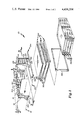
- FIG. 1 is an exploded perspective view of the invention.
- FIG. 2 is a sectional view taken along line 2--2 of FIG. 1.
- FIG. 3 is a sectional view taken along line 3--3 of FIG. 1.
- FIG. 4 shows the blank from which the rear support is formed.
- FIG. 5 is a plan view showing the side support member blank.
- the flat file is comprised of a shell 12 having a top 14, a bottom 16, a back 18, an open front 20 and first and second sides 22 and 24, respectively.
- First and second support members 26 and 28, respectively, are placed inside shell 12 and overlie the inner surfaces of first and second sides 22 and 24. The details of support members 26 and 28 are described more fully hereinafter.
- a rear support member 30 overlies backwall 18.
- a plurality of shelves 32 are provided for engagement with support members 26, 28 and 30, said shelves 32 being comprised of a double thickness of corrugated board and having, if desired, a channel-shaped metal front edge 34 placed thereover.
- a rectangular metal frame 36 frames the open front 20 of shell 12.
- a number of drawers 38 are thence inserted between shelves 32.
- the construction of drawers 38 is conventional and may be of several known types in the art.
- first support member 26 is shown therein in blank form.
- second support member 28 is, in blank form, identical to first support member 26.
- a support member 26 is comprised of a rectangular main panel 40 having hinged thereto a front spacing panel 44 by means of foldline 42. Hinged to the opposite side of front spacing panel 44 is first front slotted panel 48 which is hingedly attached at foldline 46. Attached to the opposite side of slotted panel 48 is second front slotted panel 52 at foldline 50. Transition panel 56 is attached to the opposite edge of second front slotted panel 52 at fold line 54. Finally, attachment flange 60 is attached at fold line 58 to transition panel 56.
- a number of slots 62 corresponding to the number of shelves 32 are formed in panels 48, 52, and 56.
- a rear transition panel 66 is attached at the opposite end of main panel 40 at fold line 64.
- First and second rear slotted panels 70 and 74 are attached at fold lines 68 and 72, respectively.
- Attachment flange 78 is attached to panel 74 at fold line 76.
- Slots 80 are formed in panels 70 and 74, slots 80 corresponding in number to the slots 62 formed at the front of support member 26. As can be seen in FIG. 5, slots 80 have a widened portion 80a adjacent attachment flange 78. Widened portion 80a serves to ease the insertion of shelves 32 into slots 80.
- front transition panel 44 is folded backwards so as to overlie main panel 40. Thence, first slotted panel 48 is folded forward again and second slotted panel 52 folded back with attachment flange 60 being folded into contact with main panel 40 and fastened thereto by any conventional means of attachment such as adhesive, staples, or the like.
- transition panel 66 is bent at right angles to main panel 40 so as to overlie the rear wall 18 of shell 12.
- first slotted panel 70 is bent so as to form an acute angle relative to transition panel 66 and then second slotted panel 74 folded forwardly in conjunction with attachment panel 78 so as to form in effect an angled shelf as shown in FIG. 2.
- FIG. 4 discloses rear support member 30 which is comprised of two outer attachment flanges 82 having a rectangular slotted panel 86 attached thereto at fold lines 84 and tapered slotted panels 90 attached to panels 86 at fold lines 88. Each pair of tapered slotted panels 90 is attached to one another at fold line 92. Slots 94 extend through panels 86 and 90 and have widened portions 94a which, like widened portions 80a, serve to ease initial insertion of shelves 32 into slots 94. As can be seen in FIG. 2, rear support member 30 is folded into a generally triangular shape with attachment flanges 82 forming the base thereof. As shown in FIG. 2, a small angle may be included between panels 90 and 86 is desired. Again, rear support 30 may be attached to shell 12 by means of staples, adhesives, or any other conventional fastening means.
Landscapes
- Assembled Shelves (AREA)
Abstract
A flat file having a number of drawers is formed of a shell having a number of shelves therein for locating the various drawers of the flat file. The shelves are located by means of shelf support members formed of corrugated board having portions which are slotted and folded into place so as to locate the shelves.
Description
Flat files in general have been known for a long time and most typically are constructed of metal. In recent years, flat files constructed of nonmetallic substances such as corrugated board and/or particle board have become popular. Such files typically have a number of shelves therein which serve to locate the drawers of the file. These shelves are typically located inside an outer shell by means of locating devices on either side of the shell. These locating devices may be formed of particle board having slots cut therein for receipt of the shelves or may be formed sets of several thicknesses of corrugated material fastened to the shell in spaced relationship between sets so as to provide slots for the shelves. The latter construction has been less than satisfactory in that such a construction requires very precise location of the corrugated portions so as to provide for the proper spacing of the shelves and therefore the drawers.
It is, therefore, an object of this invention to provide a support member which is easily and inexpensively manufactured and in which the spacing of the shelves can be controlled and dictated to a high degree.
A rectangular shell has a top, a bottom, a back, an open front and two sides. Overlying each side are first and second support members formed of corrugated fiberboard or the like. Each support member has a portion at the front which is folded backwards overlying the main panel of the support member and which portion is slotted for receipt of shelves for supporting and separating the various drawers. A slotted portion is also folded forward from the rear of the main panel of this support member, this portion having widened slots at the forward edge thereof to ease the insertion of the shelves. A rear center support may also be added and this, too, is formed of corrugated material which is slotted for receipt of the shelves.
These and other objects and advantages of the invention will become readily apparent as the following description is read in conjunction with the accompanying drawings wherein like reference numerals refer to the same or similar parts throughout the several views.
FIG. 1 is an exploded perspective view of the invention.
FIG. 2 is a sectional view taken along line 2--2 of FIG. 1.
FIG. 3 is a sectional view taken along line 3--3 of FIG. 1.
FIG. 4 shows the blank from which the rear support is formed.
FIG. 5 is a plan view showing the side support member blank.
The flat file, generally 10, is comprised of a shell 12 having a top 14, a bottom 16, a back 18, an open front 20 and first and second sides 22 and 24, respectively. First and second support members 26 and 28, respectively, are placed inside shell 12 and overlie the inner surfaces of first and second sides 22 and 24. The details of support members 26 and 28 are described more fully hereinafter. A rear support member 30 overlies backwall 18. A plurality of shelves 32 are provided for engagement with support members 26, 28 and 30, said shelves 32 being comprised of a double thickness of corrugated board and having, if desired, a channel-shaped metal front edge 34 placed thereover. If desired, a rectangular metal frame 36 frames the open front 20 of shell 12. A number of drawers 38 are thence inserted between shelves 32. The construction of drawers 38 is conventional and may be of several known types in the art.
Turning to FIG. 5, first support member 26 is shown therein in blank form. Of course, it can be appreciated that second support member 28 is, in blank form, identical to first support member 26. As shown in FIG. 5, a support member 26 is comprised of a rectangular main panel 40 having hinged thereto a front spacing panel 44 by means of foldline 42. Hinged to the opposite side of front spacing panel 44 is first front slotted panel 48 which is hingedly attached at foldline 46. Attached to the opposite side of slotted panel 48 is second front slotted panel 52 at foldline 50. Transition panel 56 is attached to the opposite edge of second front slotted panel 52 at fold line 54. Finally, attachment flange 60 is attached at fold line 58 to transition panel 56. A number of slots 62 corresponding to the number of shelves 32 are formed in panels 48, 52, and 56. A rear transition panel 66 is attached at the opposite end of main panel 40 at fold line 64. First and second rear slotted panels 70 and 74 are attached at fold lines 68 and 72, respectively. Attachment flange 78 is attached to panel 74 at fold line 76. Slots 80 are formed in panels 70 and 74, slots 80 corresponding in number to the slots 62 formed at the front of support member 26. As can be seen in FIG. 5, slots 80 have a widened portion 80a adjacent attachment flange 78. Widened portion 80a serves to ease the insertion of shelves 32 into slots 80. As can be seen in FIG. 2, front transition panel 44 is folded backwards so as to overlie main panel 40. Thence, first slotted panel 48 is folded forward again and second slotted panel 52 folded back with attachment flange 60 being folded into contact with main panel 40 and fastened thereto by any conventional means of attachment such as adhesive, staples, or the like.
Similarly, at the rear end of main panel 40, transition panel 66 is bent at right angles to main panel 40 so as to overlie the rear wall 18 of shell 12. Hence, first slotted panel 70 is bent so as to form an acute angle relative to transition panel 66 and then second slotted panel 74 folded forwardly in conjunction with attachment panel 78 so as to form in effect an angled shelf as shown in FIG. 2.
FIG. 4 discloses rear support member 30 which is comprised of two outer attachment flanges 82 having a rectangular slotted panel 86 attached thereto at fold lines 84 and tapered slotted panels 90 attached to panels 86 at fold lines 88. Each pair of tapered slotted panels 90 is attached to one another at fold line 92. Slots 94 extend through panels 86 and 90 and have widened portions 94a which, like widened portions 80a, serve to ease initial insertion of shelves 32 into slots 94. As can be seen in FIG. 2, rear support member 30 is folded into a generally triangular shape with attachment flanges 82 forming the base thereof. As shown in FIG. 2, a small angle may be included between panels 90 and 86 is desired. Again, rear support 30 may be attached to shell 12 by means of staples, adhesives, or any other conventional fastening means.
While the preferred embodiments of the present invention have been described, it should be understood that various changes, adaptations and modifications may be made therein without departing from the spirit of the invention and the scope of the appended claims.
Claims (8)
1. A flat-file having a plurality of drawers located in a shell having a top, a bottom, a back, an open front, first and second sides and at least one shelf located between and parallel to the said top and said bottom, the improvement comprising at least one shelf support member, said shell and said support member being formed of a foldable material, said support member comprising:
a main panel located inside of and parallel to one of said sides; and
at least one front shelf support panel attached to the front of said main panel, said front support panel comprising at least one slot therein for engaging and supporting a shelf;
a front spacing panel spacing said front support panel from said main panel, said front support panel and said front spacing panel overlying said main panel; and
a rear support panel attached to the rear of said main panel, said rear support panel comprising at least one slot therein for engaging and supporting a shelf.
2. The flat-file of claim 1 further comprising a second support panel overlying and attached to said front support panel.
3. The flat-file of claim 5 further comprising means for fastening said support panels to said main panel.
4. The flat-file of claim 1 further comprising a rear spacing panel, said rear spacing panel being attached to and extending normally inwardly from said main panel and said rear support panel extending forwardly toward said main panel.
5. The flat-file of claim 4 wherein each said panel slot has a widened portion at the forward end thereof.
6. The flat-file of claim 4 further comprising means for fastening said rear support panel to said main panel.
7. The flat-file of claim 1 further comprising a back support member, said back support member being attached to said back and having at least one slot therein for receiving a shelf therein.
8. The flat-file of claim 7 wherein said back support member extends forwardly from said back, each said slot having a widened portion at the front thereof.
Priority Applications (1)
| Application Number | Priority Date | Filing Date | Title |
|---|---|---|---|
| US06/321,699 US4436354A (en) | 1981-11-16 | 1981-11-16 | Flat-file |
Applications Claiming Priority (1)
| Application Number | Priority Date | Filing Date | Title |
|---|---|---|---|
| US06/321,699 US4436354A (en) | 1981-11-16 | 1981-11-16 | Flat-file |
Publications (1)
| Publication Number | Publication Date |
|---|---|
| US4436354A true US4436354A (en) | 1984-03-13 |
Family
ID=23251660
Family Applications (1)
| Application Number | Title | Priority Date | Filing Date |
|---|---|---|---|
| US06/321,699 Expired - Fee Related US4436354A (en) | 1981-11-16 | 1981-11-16 | Flat-file |
Country Status (1)
| Country | Link |
|---|---|
| US (1) | US4436354A (en) |
Cited By (4)
| Publication number | Priority date | Publication date | Assignee | Title |
|---|---|---|---|---|
| DE3643526A1 (en) * | 1986-12-19 | 1988-07-21 | Zedek Bv | Kit for a storage container for objects |
| GB2328606A (en) * | 1997-08-30 | 1999-03-03 | Mark William Eastcott | Cardboard CD rack |
| US20070051728A1 (en) * | 2005-09-06 | 2007-03-08 | Bradford Company | Container with locking strips |
| US10064482B2 (en) * | 2014-08-20 | 2018-09-04 | Standstand Inc. | Collapsible stand |
Citations (10)
| Publication number | Priority date | Publication date | Assignee | Title |
|---|---|---|---|---|
| US930114A (en) | 1909-03-08 | 1909-08-03 | James F Adams | Knockdown box. |
| US1125902A (en) | 1913-04-30 | 1915-01-19 | Emmons Bryant | Paper box. |
| US2074315A (en) | 1932-11-12 | 1937-03-16 | Neely Frank Rodgers | Box |
| US2221024A (en) | 1939-05-03 | 1940-11-12 | Eastman Kodak Co | Film box for miniature film |
| US2904382A (en) | 1956-05-21 | 1959-09-15 | Frank P Mitten | Shipping and storage container |
| US3084790A (en) | 1961-04-24 | 1963-04-09 | Kvp Sutherland Paper Co | Carton |
| US3365258A (en) | 1966-08-17 | 1968-01-23 | Downing Displays | Knock-down counter construction |
| US3554429A (en) | 1968-12-16 | 1971-01-12 | Shell Containers Inc | Container with partition supporting means |
| US4080023A (en) | 1976-12-13 | 1978-03-21 | Bair Carl J | Collapsible multiple shelf file |
| US4319795A (en) | 1979-11-29 | 1982-03-16 | Fellowes Manufacturing Company | Flat file |
-
1981
- 1981-11-16 US US06/321,699 patent/US4436354A/en not_active Expired - Fee Related
Patent Citations (10)
| Publication number | Priority date | Publication date | Assignee | Title |
|---|---|---|---|---|
| US930114A (en) | 1909-03-08 | 1909-08-03 | James F Adams | Knockdown box. |
| US1125902A (en) | 1913-04-30 | 1915-01-19 | Emmons Bryant | Paper box. |
| US2074315A (en) | 1932-11-12 | 1937-03-16 | Neely Frank Rodgers | Box |
| US2221024A (en) | 1939-05-03 | 1940-11-12 | Eastman Kodak Co | Film box for miniature film |
| US2904382A (en) | 1956-05-21 | 1959-09-15 | Frank P Mitten | Shipping and storage container |
| US3084790A (en) | 1961-04-24 | 1963-04-09 | Kvp Sutherland Paper Co | Carton |
| US3365258A (en) | 1966-08-17 | 1968-01-23 | Downing Displays | Knock-down counter construction |
| US3554429A (en) | 1968-12-16 | 1971-01-12 | Shell Containers Inc | Container with partition supporting means |
| US4080023A (en) | 1976-12-13 | 1978-03-21 | Bair Carl J | Collapsible multiple shelf file |
| US4319795A (en) | 1979-11-29 | 1982-03-16 | Fellowes Manufacturing Company | Flat file |
Cited By (5)
| Publication number | Priority date | Publication date | Assignee | Title |
|---|---|---|---|---|
| DE3643526A1 (en) * | 1986-12-19 | 1988-07-21 | Zedek Bv | Kit for a storage container for objects |
| GB2328606A (en) * | 1997-08-30 | 1999-03-03 | Mark William Eastcott | Cardboard CD rack |
| US20070051728A1 (en) * | 2005-09-06 | 2007-03-08 | Bradford Company | Container with locking strips |
| US7654408B2 (en) * | 2005-09-06 | 2010-02-02 | Bradford Company | Container with locking strips |
| US10064482B2 (en) * | 2014-08-20 | 2018-09-04 | Standstand Inc. | Collapsible stand |
Similar Documents
| Publication | Publication Date | Title |
|---|---|---|
| US5469961A (en) | Combined minidisc box | |
| US4318628A (en) | Connecting device for construction panels | |
| US4295693A (en) | Knocked-down cabinet | |
| US5392902A (en) | Merchandise display device | |
| US4076203A (en) | Wall shelf arrangement | |
| USD254883S (en) | Storage case for stationery articles or the like | |
| US4296982A (en) | Knock-down cabinet assembly | |
| USD250187S (en) | Computer cabinet | |
| USD243900S (en) | Cabinet for photographic sheet products | |
| CA2287515A1 (en) | Knock-down hang-on storage unit for portable partition systems | |
| US4062452A (en) | Document filing apparatus | |
| US5630658A (en) | Hemmed edge file holder | |
| USD262763S (en) | Desk unit or similar article | |
| USD412079S (en) | Shelf member | |
| US2350280A (en) | Cabinet | |
| USD247403S (en) | Combined multiple cabinet and shelf storage unit | |
| US4436354A (en) | Flat-file | |
| US5695061A (en) | Literature holder and blank therefor | |
| US4805860A (en) | Shelf support brackets | |
| US4304354A (en) | Drawer organizer | |
| US4014120A (en) | Picture mount and support | |
| US3120413A (en) | Multiple drawer box | |
| USD386335S (en) | Drawer divider unit | |
| USD321999S (en) | Disk storage case | |
| US2831285A (en) | Display mount and easel |
Legal Events
| Date | Code | Title | Description |
|---|---|---|---|
| AS | Assignment |
Owner name: LIBERTY CARTON CO., 870 LOUISIANA AVE., SOUTH MINN Free format text: ASSIGNMENT OF ASSIGNORS INTEREST.;ASSIGNOR:THORUD, STANLEY R.;REEL/FRAME:003958/0590 Effective date: 19811104 |
|
| FEPP | Fee payment procedure |
Free format text: MAINTENANCE FEE REMINDER MAILED (ORIGINAL EVENT CODE: REM.); ENTITY STATUS OF PATENT OWNER: LARGE ENTITY |
|
| LAPS | Lapse for failure to pay maintenance fees | ||
| STCH | Information on status: patent discontinuation |
Free format text: PATENT EXPIRED DUE TO NONPAYMENT OF MAINTENANCE FEES UNDER 37 CFR 1.362 |
|
| FP | Lapsed due to failure to pay maintenance fee |
Effective date: 19880313 |