US4433396A - Sonar receivers - Google Patents
Sonar receivers Download PDFInfo
- Publication number
- US4433396A US4433396A US06/300,128 US30012881A US4433396A US 4433396 A US4433396 A US 4433396A US 30012881 A US30012881 A US 30012881A US 4433396 A US4433396 A US 4433396A
- Authority
- US
- United States
- Prior art keywords
- sonar
- sonar receiver
- transducer
- reflector
- transducers
- Prior art date
- Legal status (The legal status is an assumption and is not a legal conclusion. Google has not performed a legal analysis and makes no representation as to the accuracy of the status listed.)
- Expired - Fee Related
Links
- 229920001971 elastomer Polymers 0.000 claims description 5
- 239000000463 material Substances 0.000 claims description 5
- 230000005855 radiation Effects 0.000 claims description 5
- 230000001360 synchronised effect Effects 0.000 claims description 2
- 238000010586 diagram Methods 0.000 description 3
- 230000000712 assembly Effects 0.000 description 2
- 238000000429 assembly Methods 0.000 description 2
- 230000006978 adaptation Effects 0.000 description 1
- 239000000853 adhesive Substances 0.000 description 1
- 230000001070 adhesive effect Effects 0.000 description 1
- XAGFODPZIPBFFR-UHFFFAOYSA-N aluminium Chemical compound [Al] XAGFODPZIPBFFR-UHFFFAOYSA-N 0.000 description 1
- 229910052782 aluminium Inorganic materials 0.000 description 1
- 239000004411 aluminium Substances 0.000 description 1
- 230000009286 beneficial effect Effects 0.000 description 1
- 230000008878 coupling Effects 0.000 description 1
- 238000010168 coupling process Methods 0.000 description 1
- 238000005859 coupling reaction Methods 0.000 description 1
- 238000006880 cross-coupling reaction Methods 0.000 description 1
- 230000000694 effects Effects 0.000 description 1
- 230000002706 hydrostatic effect Effects 0.000 description 1
- 230000003993 interaction Effects 0.000 description 1
- 238000012986 modification Methods 0.000 description 1
- 230000004048 modification Effects 0.000 description 1
- 229920002635 polyurethane Polymers 0.000 description 1
- 239000004814 polyurethane Substances 0.000 description 1
- 238000005070 sampling Methods 0.000 description 1
Images
Classifications
-
- G—PHYSICS
- G01—MEASURING; TESTING
- G01S—RADIO DIRECTION-FINDING; RADIO NAVIGATION; DETERMINING DISTANCE OR VELOCITY BY USE OF RADIO WAVES; LOCATING OR PRESENCE-DETECTING BY USE OF THE REFLECTION OR RERADIATION OF RADIO WAVES; ANALOGOUS ARRANGEMENTS USING OTHER WAVES
- G01S15/00—Systems using the reflection or reradiation of acoustic waves, e.g. sonar systems
- G01S15/02—Systems using the reflection or reradiation of acoustic waves, e.g. sonar systems using reflection of acoustic waves
- G01S15/06—Systems determining the position data of a target
- G01S15/42—Simultaneous measurement of distance and other co-ordinates
-
- G—PHYSICS
- G10—MUSICAL INSTRUMENTS; ACOUSTICS
- G10K—SOUND-PRODUCING DEVICES; METHODS OR DEVICES FOR PROTECTING AGAINST, OR FOR DAMPING, NOISE OR OTHER ACOUSTIC WAVES IN GENERAL; ACOUSTICS NOT OTHERWISE PROVIDED FOR
- G10K11/00—Methods or devices for transmitting, conducting or directing sound in general; Methods or devices for protecting against, or for damping, noise or other acoustic waves in general
- G10K11/18—Methods or devices for transmitting, conducting or directing sound
- G10K11/26—Sound-focusing or directing, e.g. scanning
- G10K11/28—Sound-focusing or directing, e.g. scanning using reflection, e.g. parabolic reflectors
Definitions
- This invention relates to sonar receivers and more particularly to reflective sonar receivers.
- the present invention seeks to provide a simplified sonar receiver.
- a sonar receiver comprising an inwardly curved reflector arranged to direct received sonar signals onto a transducer system, which transducer system comprises an array of transducers distributed over an inwardly curved path facing the reflector such that each transducer is responsive to sonar signals received from a particular direction to provide an output signal indicative of a reflecting object the amplitude of which signal is related to distance of the reflecting object, and sequential selection means arranged to couple the outputs of the transducers sequentially to a display device for indicating in response to a signal the direction and distance of a reflecting object.
- each transducer is directed towards the centre of the reflector but slight divergence from the centre is acceptable.
- the curved path is preferably substantially compliant with the locus of the focus of all possible object positions at a given range. However, the curved path can diverge from this locus provided it remains within the depth of field of the reflector within the intended operating range.
- the reflector is elliptical.
- the reflector may be of constant radius.
- the radius of the transducer may be equal to half the radius of curvature of the reflector measured at its centre.
- the transducers of the array may be mounted on individual resilient mounts. This mounting reduces or eliminates cross coupling between elements and therefore beams.
- the resilient mountings may be formed by pressure release rubber.
- the transducer and mount assemblies may be secured between two layers of flexible material with the transducers secured to one of the layers, which is transparent to sonar radiation, and the mounts secured to the other of the layers.
- the transducer assembly is preferably mounted in an open sided housing which is shaped to corresond to the curved path and to support the assembly such that the transducer faces are positioned along the path.
- said one layer is arranged to seal the open side of the housing.
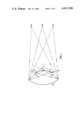
- FIG. 1 is a diagram showing the focusing effect of an inwardly curved reflector
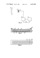
- FIG. 2 is a schematic illustration of a sonar receiver constructed in accordance with the invention.
- FIG. 3 is a cross sectional view of the transducer system of the receiver of FIG. 2;
- FIG. 4 is a plan view of the transducer system of FIG. 2.
- a reflector 10 has a reflecting surface which is inwardly curved in one plane and which may be of the form of an ellipse.
- the diagram illustrates the path of radiation reflected from an object positioned at three positions 01, 02, 03, at a constant distance from the mirror, to the mirror and the reflection of that radiation to points of focus f1, f2, f3. If sufficient points were taken, then due to the curvature of the reflector, the locus of the focus of all possible object positions at that given range would define a path 11 that is inwardly curved and which faces the reflector.
- each object position 01, 02, 03, at that given distance will be focused at a unique position on the curved path so that if we arrange for a transducer to be located at this position it would respond only to sonar radiation arriving from the direction of the object and variation of the object distance within a predetermined operating range will result in variation of the amplitude of the transducer signal as a function of the object distance. Accordingly, the presence of an output signal on the transducer indicates the presence of a sonar reflecting object in a given direction and the amplitude of that signal can be used to indicate its target strength.
- the present invention is based on this realisation and employs an array of transducers distributed over the path so that the direction of a sonar reflecting object is indicated in dependence upon which of the transducers is excited.
- the array effectively provides a beam former sampling system which does not require complex electronics to resolve bearing and distance information.
- the schematic diagram of a sonar receiver constructed in accordance with the invention is illustrated in FIG. 2 and employs a transducer system as is illustrated in FIGS. 3 and 4.
- the transducer system comprises fifteen rows of three piezoelectric transducer elements 12. As can be seen from FIG. 4 the transducers in the rows are in alignment and each group of three, forming each row, are mounted on a common mount 13 which is formed by a block of pressure release rubber.
- the transducer/mount assemblies are spaced equidistantly one from another and are secured by adhesive between two thin sheets 14, 15 of flexible material e.g. rubber or polyurethane so that all the transducers are stuck to one sheet 14 and all the mounts to the other sheet 15.
- the sheet 14 must be substantially transparent to sonar signals and forms an acoustic window.
- the assembly so produced is very flexible and is mounted inside a hollow aluminium housing 16 having internal dimensions sized to accept the transducer assembly.
- the housing is a substantially rectangular shape open on one side and having the perimeter of the opening shaped to comply substantially with the curved path corresponding to the locus of the focus of all possible object positions at a given range of a reflector with which the transducer will be used.
- the inside base of the housing is also shaped to this path.
- the layer 15 is considerably more compliant than the layer 14 so that under increased hydrostatic pressure the layer 15 will deform significantly more than layer 14 thereby retaining the design curvature of layer 14.
- the transducer assembly is introduced into the housing whereupon the two sheets conform to the shape of the curved path.
- the sheet 14 overlaps the perimeter of the housing and is secured thereto by a clamping plate 16a so that the housing is effectively sealed and contains air. It will be appreciated that the transducers are thereby positioned on the required path.
- the described transducer system is identified as 17 in FIG. 2 and is mounted at the focus of a sonar reflection 18 of elliptical configuration with which it is desired to operate.
- the outputs 19 of the transducers are coupled each to a particular input of a sequential selector 20 the output of which is coupled to a display device 21 e.g. a C.R.T. display for displaying direction on the X axis and distance on the Y axis.
- the sequential selector is synchronised with a display scan by means of the synchronising connection 22 so that the transducer outputs are coupled sequentially to the display during each scan and in synchronism with the scan.
- the occurence of a signal is then indicated by a line on the display the position of the line on the X axis indicating the direction of the sonar reflecting objects and the length of the line indicating on the Y axis the distance.
- the transducers it is not essential for the transducers to be mounted on a path that conforms exactly with the calculated locus of the focus points provided they are positioned within the depth of focus of the reflector at the intended operating range. In practice it is convenient to make the reflector elliptical and to mount the transducers on a curved path of constant radius. The radius can be made equal to half the radius of curvature of the reflector measured at its centre. The mounting of the transducers on separate blocks of pressure released rubber is beneficial in that it reduces interaction between transducers by mechanical coupling.
Landscapes
- Physics & Mathematics (AREA)
- Engineering & Computer Science (AREA)
- Acoustics & Sound (AREA)
- Radar, Positioning & Navigation (AREA)
- Remote Sensing (AREA)
- Computer Networks & Wireless Communication (AREA)
- General Physics & Mathematics (AREA)
- Multimedia (AREA)
- Measurement Of Velocity Or Position Using Acoustic Or Ultrasonic Waves (AREA)
- Transducers For Ultrasonic Waves (AREA)
Abstract
Description
Claims (16)
Applications Claiming Priority (2)
| Application Number | Priority Date | Filing Date | Title |
|---|---|---|---|
| GB8029193 | 1980-09-10 | ||
| GB8029193A GB2083625B (en) | 1980-09-10 | 1980-09-10 | Improvements in or relating to sonar receivers |
Publications (1)
| Publication Number | Publication Date |
|---|---|
| US4433396A true US4433396A (en) | 1984-02-21 |
Family
ID=10515977
Family Applications (1)
| Application Number | Title | Priority Date | Filing Date |
|---|---|---|---|
| US06/300,128 Expired - Fee Related US4433396A (en) | 1980-09-10 | 1981-09-08 | Sonar receivers |
Country Status (4)
| Country | Link |
|---|---|
| US (1) | US4433396A (en) |
| DE (1) | DE3132283A1 (en) |
| FR (1) | FR2489967B1 (en) |
| GB (1) | GB2083625B (en) |
Cited By (5)
| Publication number | Priority date | Publication date | Assignee | Title |
|---|---|---|---|---|
| US4791430A (en) * | 1986-06-12 | 1988-12-13 | Agtronics Pty. Limited | Ultrasonic antenna |
| US5119801A (en) * | 1988-02-04 | 1992-06-09 | Dornier Medizintechnik Gmbh | Piezoelectric shock wave generator |
| US20130176816A1 (en) * | 2012-01-11 | 2013-07-11 | Seiko Epson Corporation | Ultrasonic transducer, ultrasonic probe, diagnostic instrument, and electronic instrument |
| WO2015086645A1 (en) | 2013-12-11 | 2015-06-18 | Evonik Industries Ag | Process for preparing alkanesulfonic acids |
| US20240111037A1 (en) * | 2022-09-29 | 2024-04-04 | Navico, Inc. | Reflective surface beamforming |
Families Citing this family (1)
| Publication number | Priority date | Publication date | Assignee | Title |
|---|---|---|---|---|
| GB2251687A (en) * | 1990-12-28 | 1992-07-15 | Watersearch Limited | Sonar apparatus |
Citations (3)
| Publication number | Priority date | Publication date | Assignee | Title |
|---|---|---|---|---|
| GB317089A (en) * | 1928-08-10 | 1930-10-02 | Goerz Optische Anstalt Ag | Improvements in or relating to apparatus for determining the direction of sound rays |
| US3243768A (en) * | 1962-06-01 | 1966-03-29 | Jr Arthur H Roshon | Integral directional electroacoustical transducer for simultaneous transmission and reception of sound |
| US3389372A (en) * | 1965-06-23 | 1968-06-18 | Smiths Industries Ltd | Echo-ranging apparatus |
Family Cites Families (8)
| Publication number | Priority date | Publication date | Assignee | Title |
|---|---|---|---|---|
| AT122627B (en) * | 1928-08-10 | 1931-05-11 | Cp Goerz Optische Anstalt Ag | Device for the approximate determination of the direction of incoming sound beams. |
| US3239801A (en) * | 1964-12-18 | 1966-03-08 | Automation Ind Inc | Liquid lens ultrasonic beam controlling device |
| GB1234237A (en) * | 1965-06-23 | 1971-06-03 | ||
| DE1516609B2 (en) * | 1966-11-10 | 1970-12-10 | Fried. Krupp Gmbh, 4300 Essen | Method and device for increasing the angular definition of the bearing display of sonar systems |
| NO126499B (en) * | 1968-12-20 | 1973-02-12 | Smiths Industries Ltd | |
| DE2529112C3 (en) * | 1975-06-30 | 1978-03-23 | Siemens Ag, 1000 Berlin Und 8000 Muenchen | Ultrasonic applicator for line-by-line ultrasound scanning of bodies |
| US4084582A (en) * | 1976-03-11 | 1978-04-18 | New York Institute Of Technology | Ultrasonic imaging system |
| DE2926182A1 (en) * | 1979-06-28 | 1981-01-22 | Siemens Ag | Ultrasonic transducer elements arrangement - sandwiches each element between matching and damping sections for coping with irregular surfaces subjected to scanning for defects |
-
1980
- 1980-09-10 GB GB8029193A patent/GB2083625B/en not_active Expired
-
1981
- 1981-08-14 DE DE19813132283 patent/DE3132283A1/en not_active Ceased
- 1981-09-03 FR FR8116777A patent/FR2489967B1/en not_active Expired
- 1981-09-08 US US06/300,128 patent/US4433396A/en not_active Expired - Fee Related
Patent Citations (3)
| Publication number | Priority date | Publication date | Assignee | Title |
|---|---|---|---|---|
| GB317089A (en) * | 1928-08-10 | 1930-10-02 | Goerz Optische Anstalt Ag | Improvements in or relating to apparatus for determining the direction of sound rays |
| US3243768A (en) * | 1962-06-01 | 1966-03-29 | Jr Arthur H Roshon | Integral directional electroacoustical transducer for simultaneous transmission and reception of sound |
| US3389372A (en) * | 1965-06-23 | 1968-06-18 | Smiths Industries Ltd | Echo-ranging apparatus |
Cited By (9)
| Publication number | Priority date | Publication date | Assignee | Title |
|---|---|---|---|---|
| US4791430A (en) * | 1986-06-12 | 1988-12-13 | Agtronics Pty. Limited | Ultrasonic antenna |
| US5119801A (en) * | 1988-02-04 | 1992-06-09 | Dornier Medizintechnik Gmbh | Piezoelectric shock wave generator |
| US20130176816A1 (en) * | 2012-01-11 | 2013-07-11 | Seiko Epson Corporation | Ultrasonic transducer, ultrasonic probe, diagnostic instrument, and electronic instrument |
| CN103208282A (en) * | 2012-01-11 | 2013-07-17 | 精工爱普生株式会社 | Ultrasonic transducer, ultrasonic probe, diagnostic instrument, and electronic instrument |
| US9348213B2 (en) * | 2012-01-11 | 2016-05-24 | Seiko Epson Corporation | Ultrasonic transducer, ultrasonic probe, diagnostic instrument, and electronic instrument |
| CN103208282B (en) * | 2012-01-11 | 2018-01-05 | 精工爱普生株式会社 | Ultrasonic transducer, ultrasonic detector, diagnostic device and electronic equipment |
| WO2015086645A1 (en) | 2013-12-11 | 2015-06-18 | Evonik Industries Ag | Process for preparing alkanesulfonic acids |
| US20240111037A1 (en) * | 2022-09-29 | 2024-04-04 | Navico, Inc. | Reflective surface beamforming |
| US12169259B2 (en) * | 2022-09-29 | 2024-12-17 | Navico, Inc. | Reflective surface beamforming |
Also Published As
| Publication number | Publication date |
|---|---|
| DE3132283A1 (en) | 1982-06-09 |
| GB2083625A (en) | 1982-03-24 |
| FR2489967B1 (en) | 1986-04-18 |
| FR2489967A1 (en) | 1982-03-12 |
| GB2083625B (en) | 1984-11-14 |
Similar Documents
| Publication | Publication Date | Title |
|---|---|---|
| US3831137A (en) | Acousto-optic underwater detector | |
| US4440025A (en) | Arc scan transducer array having a diverging lens | |
| US3895340A (en) | Acoustic camera apparatus | |
| US3243768A (en) | Integral directional electroacoustical transducer for simultaneous transmission and reception of sound | |
| US3898840A (en) | Multi-frequency ultrasonic search unit | |
| US6128250A (en) | Bottom-deployed, upward looking hydrophone assembly | |
| US5834877A (en) | Ultrasonic transducer units for web detection and the like | |
| US3736552A (en) | Acoustic imaging device using multiple element electret transducer | |
| US3458854A (en) | Echo detection and ranging system | |
| US3895339A (en) | Acoustic camera apparatus | |
| US3718898A (en) | Transducer | |
| US4433396A (en) | Sonar receivers | |
| US3355579A (en) | Correlation apparatus | |
| GB2110503A (en) | Ultrasonic probe | |
| US4641291A (en) | Phased array Doppler sonar transducer | |
| US4704556A (en) | Transducers | |
| US3901352A (en) | Underwater reflector of sound waves | |
| US3800273A (en) | Portable sonar system | |
| US4680967A (en) | Ultrasonic angle test probe having at least two transducers | |
| US2961636A (en) | Electro-acoustic transducer for omnidirectional search | |
| US3783967A (en) | Focusing protective enclosure for ultrasonic transducer | |
| EP0015159B1 (en) | A shock or pressure wave detecting transducer assembly | |
| US5333129A (en) | Acoustic imaging in the ocean using ambinet noise | |
| EP0293803A2 (en) | Fan-shape scanning ultrasonic flaw detecting apparatus | |
| US4222632A (en) | Light receiving and reflecting device |
Legal Events
| Date | Code | Title | Description |
|---|---|---|---|
| AS | Assignment |
Owner name: PLESSEY OVERSEAS LIMITED, VICARAGE LANE, ILFORD, E Free format text: ASSIGNMENT OF ASSIGNORS INTEREST.;ASSIGNORS:JOHNSON, PHILLIP L. M.;WALDEN, JOHN R.;REEL/FRAME:003930/0768 Effective date: 19810307 Owner name: PLESSEY OVERSEAS LIMITED, VICARAGE LANE, ILFORD, E Free format text: ASSIGNMENT OF ASSIGNORS INTEREST;ASSIGNORS:JOHNSON, PHILLIP L. M.;WALDEN, JOHN R.;REEL/FRAME:003930/0768 Effective date: 19810307 |
|
| FEPP | Fee payment procedure |
Free format text: PAYOR NUMBER ASSIGNED (ORIGINAL EVENT CODE: ASPN); ENTITY STATUS OF PATENT OWNER: LARGE ENTITY |
|
| MAFP | Maintenance fee payment |
Free format text: PAYMENT OF MAINTENANCE FEE, 4TH YEAR, PL 96-517 (ORIGINAL EVENT CODE: M170); ENTITY STATUS OF PATENT OWNER: LARGE ENTITY Year of fee payment: 4 |
|
| AS | Assignment |
Owner name: GEC-MARCONI LIMITED, THE GROVE, WARREN LANE, STANM Free format text: ASSIGNMENT OF ASSIGNORS INTEREST.;ASSIGNOR:PLESSEY OVERSEAS LIMITED;REEL/FRAME:005439/0343 Effective date: 19900713 Owner name: GEC-MARCONI LIMITED, ENGLAND Free format text: ASSIGNMENT OF ASSIGNORS INTEREST;ASSIGNOR:PLESSEY OVERSEAS LIMITED;REEL/FRAME:005439/0343 Effective date: 19900713 |
|
| MAFP | Maintenance fee payment |
Free format text: PAYMENT OF MAINTENANCE FEE, 8TH YEAR, PL 96-517 (ORIGINAL EVENT CODE: M171); ENTITY STATUS OF PATENT OWNER: LARGE ENTITY Year of fee payment: 8 |
|
| FEPP | Fee payment procedure |
Free format text: MAINTENANCE FEE REMINDER MAILED (ORIGINAL EVENT CODE: REM.); ENTITY STATUS OF PATENT OWNER: LARGE ENTITY |
|
| LAPS | Lapse for failure to pay maintenance fees | ||
| FP | Lapsed due to failure to pay maintenance fee |
Effective date: 19960221 |
|
| STCH | Information on status: patent discontinuation |
Free format text: PATENT EXPIRED DUE TO NONPAYMENT OF MAINTENANCE FEES UNDER 37 CFR 1.362 |