US4431063A - Drive mechanism for drill - Google Patents
Drive mechanism for drill Download PDFInfo
- Publication number
- US4431063A US4431063A US06/309,867 US30986781A US4431063A US 4431063 A US4431063 A US 4431063A US 30986781 A US30986781 A US 30986781A US 4431063 A US4431063 A US 4431063A
- Authority
- US
- United States
- Prior art keywords
- drive
- drill
- housing
- shaft
- gear
- Prior art date
- Legal status (The legal status is an assumption and is not a legal conclusion. Google has not performed a legal analysis and makes no representation as to the accuracy of the status listed.)
- Expired - Lifetime
Links
- 239000011435 rock Substances 0.000 claims abstract description 10
- 208000027418 Wounds and injury Diseases 0.000 claims abstract 2
- 230000006378 damage Effects 0.000 claims abstract 2
- 208000014674 injury Diseases 0.000 claims abstract 2
- 239000002245 particle Substances 0.000 claims description 10
- 239000000314 lubricant Substances 0.000 claims description 5
- 230000013011 mating Effects 0.000 claims description 4
- 239000002184 metal Substances 0.000 claims 5
- 239000012634 fragment Substances 0.000 abstract 1
- 238000005192 partition Methods 0.000 abstract 1
- 238000005553 drilling Methods 0.000 description 5
- 230000005540 biological transmission Effects 0.000 description 3
- 230000000694 effects Effects 0.000 description 3
- 241000239290 Araneae Species 0.000 description 2
- 238000005452 bending Methods 0.000 description 1
- 150000001875 compounds Chemical class 0.000 description 1
- 238000005520 cutting process Methods 0.000 description 1
- 239000000428 dust Substances 0.000 description 1
- 238000005461 lubrication Methods 0.000 description 1
- 230000007257 malfunction Effects 0.000 description 1
- 238000005065 mining Methods 0.000 description 1
- 238000012856 packing Methods 0.000 description 1
- 238000007789 sealing Methods 0.000 description 1
- 229920003051 synthetic elastomer Polymers 0.000 description 1
- 239000005061 synthetic rubber Substances 0.000 description 1
Images


Classifications
-
- E—FIXED CONSTRUCTIONS
- E21—EARTH DRILLING; MINING
- E21B—EARTH DRILLING, e.g. DEEP DRILLING; OBTAINING OIL, GAS, WATER, SOLUBLE OR MELTABLE MATERIALS OR A SLURRY OF MINERALS FROM WELLS
- E21B19/00—Handling rods, casings, tubes or the like outside the borehole, e.g. in the derrick; Apparatus for feeding the rods or cables
- E21B19/08—Apparatus for feeding the rods or cables; Apparatus for increasing or decreasing the pressure on the drilling tool; Apparatus for counterbalancing the weight of the rods
- E21B19/084—Apparatus for feeding the rods or cables; Apparatus for increasing or decreasing the pressure on the drilling tool; Apparatus for counterbalancing the weight of the rods with flexible drawing means, e.g. cables
-
- E—FIXED CONSTRUCTIONS
- E21—EARTH DRILLING; MINING
- E21B—EARTH DRILLING, e.g. DEEP DRILLING; OBTAINING OIL, GAS, WATER, SOLUBLE OR MELTABLE MATERIALS OR A SLURRY OF MINERALS FROM WELLS
- E21B19/00—Handling rods, casings, tubes or the like outside the borehole, e.g. in the derrick; Apparatus for feeding the rods or cables
- E21B19/08—Apparatus for feeding the rods or cables; Apparatus for increasing or decreasing the pressure on the drilling tool; Apparatus for counterbalancing the weight of the rods
-
- Y—GENERAL TAGGING OF NEW TECHNOLOGICAL DEVELOPMENTS; GENERAL TAGGING OF CROSS-SECTIONAL TECHNOLOGIES SPANNING OVER SEVERAL SECTIONS OF THE IPC; TECHNICAL SUBJECTS COVERED BY FORMER USPC CROSS-REFERENCE ART COLLECTIONS [XRACs] AND DIGESTS
- Y10—TECHNICAL SUBJECTS COVERED BY FORMER USPC
- Y10T—TECHNICAL SUBJECTS COVERED BY FORMER US CLASSIFICATION
- Y10T74/00—Machine element or mechanism
- Y10T74/17—Rotary driven device adjustable during operation relative to its supporting structure
Definitions
- This invention relates to a drive mechanism for a drill of a type used to drill elongated holes in the roofs of mine shafts.
- the drilled holes are used to receive roof bolts which are, insofar as possible, secured into rock to prevent the falling or collapse of the mine shaft roof.
- roof bolts which are, insofar as possible, secured into rock to prevent the falling or collapse of the mine shaft roof.
- mine shaft roofs are secured by a large number of such roof bolts, e.g., one for each four feet or so.
- a drill drive which as been found to be effective for drilling such roof bolt holes is described in U.S. Pat. No. 4,172,391 filed in the name of Michael O. Dressel, one of the coinventors herein.
- This drive mechanism includes means for translating and rotating a flexible drill shaft consisting of a string of articulated shaft elements which, when rotated in the drilling direction, tend to tighten and lock together to form a rigid drill shaft and which, when turned in the opposite direction, unlock from each other to cause the shaft to become flexible so that it can be curved as needed for storage.
- Such a drilling mechanism and shaft is usually carried on a mining vehicle which is built sufficiently low that it, and an operator, can move through mine shafts no more than four feet tall. Thus most of the drill shaft must be stored horizontally since it is long enough to drill holes to ten feet or more up into the roof of the mine.
- the drill drive mechanism includes a chain drive with a chain consisting of special links on each side of the drill shaft, each link including a hollow center section adapted to enclose approximately one half the circumference of the drill shaft and containing internal grooves which mate with helical projections on the drill shaft sections when the links are interlocked around the shaft.
- These special links also include projections which interlock with corresponding projections on the opposite chain, thus causing the special chain links to be tightly locked around the shaft.
- the entire chain drive assembly is rotated with the mating helical projections on the shaft and the grooves on the links carrying the shaft in a rotating manner.
- the endless chain drive is actuated by means discussed below.
- the chain drive itself does not require lubricant; however, it is necessary to provide continuous lubrication for the worm drive to the chain sprockets as well as for the main gearbox.
- a high speed rotary seal between the bottom plate of the rotary housing, which serves also as the top of the gearbox, and the upper part of the sidewall of the gearbox, which is stationary.
- the gears driving the worm gears are in the gearbox and drive through seals in said bottom plate to the worm drive shafts which mesh with the chain drive gears in separate housings adjacent the chain and chain sprockets. These separate housings permit the use of a preferred worm drive lubricant which is separated from the transmission oil in the gearbox.
- FIG. 1 is a perspective view, shown partly broken away, of a part of a drill drive mechanism incorporating our invention
- FIG. 2 is a sectional view of our drill drive mechanism showing parts and structure not visible in FIG. 1;
- FIG. 3 is a sectional view taken along line 3--3 of FIG. 2;
- FIG. 4 is a sectional view taken along line 4--4 of FIG. 2.
- FIG. 1 is a perspective view, shown partly broken away for clarity, of the portion of the drive mechanism shown generally at numeral 10 whose function is to provide the axial drive of the drill shaft 12.
- shaft 12 incorporates a series of generally helically arranged projections 14 separated by notches 16 which are axially aligned as the shaft 12 passes through the drive mechanism 10.
- the shaft 12 which is formed of a plurality of connected sections can articulate behind the drive mechanism to facilitate bending when not under load.
- the drive mechanism includes two pairs of drive sprockets which are driven by means external to the assembly of FIG. 1, of which one such sprocket is shown at numeral 18 carried on a drive shaft 20.
- a similar sprocket is carried on a drive shaft 22 which is shown broken away to show other parts of the structure.
- Two additional drive sprockets (not shown) are located at the opposite ends of shafts 20 and 22.
- a set of four idler sprockets are also included, including sprockets 24 on a shaft 26 and sprocket 28 on a shaft 30.
- an additional pair of idler sprockets are carried at the opposite ends of shafts 26 and 30.
- Each of the drive links 36 is formed with a hollow center section 36a which is adapted to wrap around one half (approximately) of the circumference of the shaft 12.
- This hollow section includes a pair of internal grooves 36b which mate with the helical projections 14 when the links are interlocked around the shaft 12.
- grooves and projections may be reversed, i.e., grooves on the drill shaft and projections on the drive links.
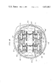
- FIG. 2 is a sectional view showing the general arrangement of the housing 40 carrying the chain drive of FIG. 1 and the gear drive means for axially and rotatably driving the drill shaft 12.
- Housing 40 which is supported on a rotatable shaft 41, consists of a pair of housing members 44 and 42 supported on a base plate 46 and fastened to an upper plate 48.
- a collar 49 bolted to upper plate 48 surrounds and guides the drill shaft 12 and includes a guide key 51 which aligns notches 16 and whose function is to assure alignment of the drill sections as they enter the drill head on retraction of the drill string.
- housing members 42 and 44 are shown each containing identical shafts 50, 50' carrying worm gears 52, 52'.
- Gears 52, 52' drive respective pairs of gears 54, 54' and 56, 56' (shown in FIG. 4) which drive the drive shafts 20 and 22.
- the shafts 50, 50' are turned by means of spur gears 58, 58' which mesh with the smaller diameter spur gear 60a of a double gear 60 supported concentric to shaft 41 by means of bearings 62, 64.
- housings 42 and 44 are both sealed from the chains and sprocket driving the drill shaft 12 as well as from the opposite side of base plate 46 which permits these housings to be filled with a preferred type of worm drive lubricant rather than the transmission oil used in the gearbox 66.
- a large diameter face seal 68 which protects gearbox 66 from the rock particles and other debris adjacent the chain drive structure and which retains the transmission oil in gearbox 66 even though the drill drive unit may be operated horizontally or at an angle.
- the seal consists of a large diameter O-ring of synthetic rubber adjacent each of an upper rim member 69 of gearbox 66 and the lower face of base plate 46, each of which seals against a large diameter sealing ring, with the rings having adjoining flat surfaces to effect a high speed dynamic seal. This seal is commercially available from The Caterpillar Company, listed as parts 5M8647 and 5P1605.
- the rotatable housing 40 is fastened to shaft 41 which is keyed to a large gear 72 supported on bearings 74 carried in the housing of gearbox 66.
- the double gear 60 in addition to the smaller diameter spur gear 60a referred to above, also carries a large diameter spur gear 60b which meshes with a gear 78 carried on a shaft 80.
- a gear 82 At the opposite end of shaft 80 is a gear 82 which meshes with a spur gear 84 keyed to a bevel gear 86.
- Bevel gear 86 forms part of a differential gearset which includes a centrally located shaft 88 and which has keyed to it a spider gear shaft 94 carrying pinion gears 96 and 98 engaged with bevel gear 86 and with an additional bevel gear 100.
- a spur gear 102 is keyed to bevel gear 100.
- a spur gear 104 which engages a spur gear 106 carried on an output shaft 108 from a hydraulic motor 110 which effectively provides the axial drive for drill
- Rotation of housing 40 and drill shaft 12 is accomplished by means of the large gear 72 which is pinned to shaft 41 such that housing 40 turns when gear 72 turns.
- Gear 72 turns when driven by spur gear 102 which is driven by a separate spur gear 103 carried on a second hydraulic motor 105 to effect rotational movement of the drill shaft 12.
- the purpose of the differential drive heretofore described is to provide a controllable axial feed for the drill shaft 12, which is coordinated with the rotational drive to eliminate any axial feed caused by rotation of drill shaft 12.
- the large drive gear 72 will be driven through gears 102 and 103 from the rotational drive motor 105 with bevel gear 100 driving gear 86 at the same speed through pinion gears 96 and 98.
- the ratios through gears 84, 82, 78 and 60a and 60b are chosen such that gear 60 and 72 rotate at the same speed which effectively cancels axial movement of shaft 12.
Abstract
Description
Claims (7)
Priority Applications (2)
| Application Number | Priority Date | Filing Date | Title |
|---|---|---|---|
| US06/309,867 US4431063A (en) | 1981-10-09 | 1981-10-09 | Drive mechanism for drill |
| JP57176485A JPS5873683A (en) | 1981-10-09 | 1982-10-08 | Drill drive mechanism |
Applications Claiming Priority (1)
| Application Number | Priority Date | Filing Date | Title |
|---|---|---|---|
| US06/309,867 US4431063A (en) | 1981-10-09 | 1981-10-09 | Drive mechanism for drill |
Publications (1)
| Publication Number | Publication Date |
|---|---|
| US4431063A true US4431063A (en) | 1984-02-14 |
Family
ID=23200018
Family Applications (1)
| Application Number | Title | Priority Date | Filing Date |
|---|---|---|---|
| US06/309,867 Expired - Lifetime US4431063A (en) | 1981-10-09 | 1981-10-09 | Drive mechanism for drill |
Country Status (2)
| Country | Link |
|---|---|
| US (1) | US4431063A (en) |
| JP (1) | JPS5873683A (en) |
Cited By (7)
| Publication number | Priority date | Publication date | Assignee | Title |
|---|---|---|---|---|
| FR2582046A1 (en) * | 1984-09-04 | 1986-11-21 | Fenyvesi Janos | DEVICE FOR DRIVING THE ROD MASS, IN PARTICULAR FOR EXECUTING A CONTINUOUS BOREHOLE WITH A HIGH DEPTH |
| EP0231414A1 (en) * | 1986-02-05 | 1987-08-12 | Kabushiki Kaisha Iseki Kaihatsu Koki | Earth auger |
| US20110114613A1 (en) * | 2009-11-17 | 2011-05-19 | Illinois Tool Works Inc. | Compact welding wire feeder |
| US20120085553A1 (en) * | 2010-10-07 | 2012-04-12 | Rod Shampine | Electrically driven coiled tubing injector assembly |
| RU2646289C1 (en) * | 2016-12-26 | 2018-03-02 | Открытое акционерное общество "Электромеханика" | Two-step reducer of powered drive of drilling unit |
| RU2646288C1 (en) * | 2016-12-26 | 2018-03-02 | Открытое акционерное общество "Электромеханика" | Multistage reducer of powered drive of drilling unit |
| CN108868582A (en) * | 2018-06-05 | 2018-11-23 | 江北建设有限公司 | A kind of drilling equipment for building |
Citations (6)
| Publication number | Priority date | Publication date | Assignee | Title |
|---|---|---|---|---|
| US527814A (en) * | 1894-10-23 | Coal-drill | ||
| US4128133A (en) * | 1976-05-07 | 1978-12-05 | The United States Of America As Represented By The Secretary Of The Interior | Torquer/thruster for flexible roofdrill |
| US4172391A (en) * | 1977-09-09 | 1979-10-30 | The United States Of America As Represented By The United States Department Of Energy | Drill drive mechanism |
| GB2063421A (en) * | 1979-11-19 | 1981-06-03 | Foster Miller Ass | Flexible Shaft for a Roof Drill |
| US4273199A (en) * | 1978-10-06 | 1981-06-16 | Blanz John H | Torquer/thruster |
| US4290494A (en) * | 1978-10-02 | 1981-09-22 | The United States Of America As Represented By The United States Department Of Energy | Flexible shaft and roof drilling system |
-
1981
- 1981-10-09 US US06/309,867 patent/US4431063A/en not_active Expired - Lifetime
-
1982
- 1982-10-08 JP JP57176485A patent/JPS5873683A/en active Pending
Patent Citations (6)
| Publication number | Priority date | Publication date | Assignee | Title |
|---|---|---|---|---|
| US527814A (en) * | 1894-10-23 | Coal-drill | ||
| US4128133A (en) * | 1976-05-07 | 1978-12-05 | The United States Of America As Represented By The Secretary Of The Interior | Torquer/thruster for flexible roofdrill |
| US4172391A (en) * | 1977-09-09 | 1979-10-30 | The United States Of America As Represented By The United States Department Of Energy | Drill drive mechanism |
| US4290494A (en) * | 1978-10-02 | 1981-09-22 | The United States Of America As Represented By The United States Department Of Energy | Flexible shaft and roof drilling system |
| US4273199A (en) * | 1978-10-06 | 1981-06-16 | Blanz John H | Torquer/thruster |
| GB2063421A (en) * | 1979-11-19 | 1981-06-03 | Foster Miller Ass | Flexible Shaft for a Roof Drill |
Cited By (9)
| Publication number | Priority date | Publication date | Assignee | Title |
|---|---|---|---|---|
| FR2582046A1 (en) * | 1984-09-04 | 1986-11-21 | Fenyvesi Janos | DEVICE FOR DRIVING THE ROD MASS, IN PARTICULAR FOR EXECUTING A CONTINUOUS BOREHOLE WITH A HIGH DEPTH |
| US4735270A (en) * | 1984-09-04 | 1988-04-05 | Janos Fenyvesi | Drillstem motion apparatus, especially for the execution of continuously operational deepdrilling |
| EP0231414A1 (en) * | 1986-02-05 | 1987-08-12 | Kabushiki Kaisha Iseki Kaihatsu Koki | Earth auger |
| US20110114613A1 (en) * | 2009-11-17 | 2011-05-19 | Illinois Tool Works Inc. | Compact welding wire feeder |
| US20120085553A1 (en) * | 2010-10-07 | 2012-04-12 | Rod Shampine | Electrically driven coiled tubing injector assembly |
| US8763709B2 (en) * | 2010-10-07 | 2014-07-01 | Schlumberger Technology Corporation | Electrically driven coiled tubing injector assembly |
| RU2646289C1 (en) * | 2016-12-26 | 2018-03-02 | Открытое акционерное общество "Электромеханика" | Two-step reducer of powered drive of drilling unit |
| RU2646288C1 (en) * | 2016-12-26 | 2018-03-02 | Открытое акционерное общество "Электромеханика" | Multistage reducer of powered drive of drilling unit |
| CN108868582A (en) * | 2018-06-05 | 2018-11-23 | 江北建设有限公司 | A kind of drilling equipment for building |
Also Published As
| Publication number | Publication date |
|---|---|
| JPS5873683A (en) | 1983-05-02 |
Similar Documents
| Publication | Publication Date | Title |
|---|---|---|
| US4431063A (en) | Drive mechanism for drill | |
| US7222682B2 (en) | Chain drive system | |
| US4172391A (en) | Drill drive mechanism | |
| GB1590324A (en) | Gathering or loading device | |
| US3309142A (en) | Cutterhead assembly for a shield-type tunneling machine | |
| JP3185011B2 (en) | Transport vehicle with upper revolving superstructure | |
| US7854402B1 (en) | Hydraulic system valving | |
| US4486051A (en) | Mining Machine | |
| GB2342421A (en) | A drive transmission unit | |
| US4327508A (en) | Trencher digging chain sprocket drive | |
| US4142596A (en) | Drive link permitting feed and rotation of drills of various sizes | |
| US4582363A (en) | Drive assembly for mining machine cutter drum | |
| CN104358569A (en) | Coal cutter and travel unit's transmission mechanism | |
| US5152185A (en) | Tram transmission | |
| US2721733A (en) | Cutter drum driven flywheel in mining machine | |
| CN112196964B (en) | Speed reducer and walking bracket with same | |
| US11814914B1 (en) | Downhole tractor drive module | |
| CN218718545U (en) | Chain with automatic noise reduction function | |
| US4648660A (en) | Method and apparatus for mining machine cutter head | |
| DE19941800A1 (en) | Drive and propulsion mechanism for cutter roll in opencast mining machine, has multi-section roll with drive units at both ends using internal roll flanges and external lateral supports | |
| CA1160475A (en) | Speed change mechanism | |
| CN112196965B (en) | Speed reducer and coal mining machine with same | |
| US1740905A (en) | Elevator | |
| CN117401343B (en) | Chain elephant trunk discharging machine | |
| SU1484936A1 (en) | Cutting unit of coal cutter-loader |
Legal Events
| Date | Code | Title | Description |
|---|---|---|---|
| AS | Assignment |
Owner name: BENDIX CORPORATION THE A CORP OF DE Free format text: ASSIGNMENT OF ASSIGNORS INTEREST.;ASSIGNORS:DRESSEL, MICHAEL O.;VARNER, HORACE M.;BRUMMERT, LAVALLE V.;AND OTHERS;REEL/FRAME:003954/0845 Effective date: 19811005 Owner name: BENDIX CORPORATION THE A CORP OF DE, DELAWARE Free format text: ASSIGNMENT OF ASSIGNORS INTEREST;ASSIGNORS:DRESSEL, MICHAEL O.;VARNER, HORACE M.;BRUMMERT, LAVALLE V.;AND OTHERS;REEL/FRAME:003954/0845 Effective date: 19811005 |
|
| AS | Assignment |
Owner name: LAKE SHORE, INC., IRON MOUNTAIN, MI 49801 A CORP Free format text: ASSIGNMENT OF ASSIGNORS INTEREST.;ASSIGNOR:BENDIX CORPORATION THE;REEL/FRAME:004212/0561 Effective date: 19831221 |
|
| STCF | Information on status: patent grant |
Free format text: PATENTED CASE |
|
| MAFP | Maintenance fee payment |
Free format text: PAYMENT OF MAINTENANCE FEE, 4TH YEAR, PL 96-517 (ORIGINAL EVENT CODE: M170); ENTITY STATUS OF PATENT OWNER: LARGE ENTITY Year of fee payment: 4 |
|
| MAFP | Maintenance fee payment |
Free format text: PAYMENT OF MAINTENANCE FEE, 8TH YEAR, PL 96-517 (ORIGINAL EVENT CODE: M171); ENTITY STATUS OF PATENT OWNER: LARGE ENTITY Year of fee payment: 8 |
|
| MAFP | Maintenance fee payment |
Free format text: PAYMENT OF MAINTENANCE FEE, 12TH YEAR, LARGE ENTITY (ORIGINAL EVENT CODE: M185); ENTITY STATUS OF PATENT OWNER: LARGE ENTITY Year of fee payment: 12 |
|
| FEPP | Fee payment procedure |
Free format text: PAYOR NUMBER ASSIGNED (ORIGINAL EVENT CODE: ASPN); ENTITY STATUS OF PATENT OWNER: LARGE ENTITY |