US442885A - Steam-condenser - Google Patents
Steam-condenser Download PDFInfo
- Publication number
- US442885A US442885A US442885DA US442885A US 442885 A US442885 A US 442885A US 442885D A US442885D A US 442885DA US 442885 A US442885 A US 442885A
- Authority
- US
- United States
- Prior art keywords
- pipe
- valve
- steam
- tank
- condenser
- Prior art date
- Legal status (The legal status is an assumption and is not a legal conclusion. Google has not performed a legal analysis and makes no representation as to the accuracy of the status listed.)
- Expired - Lifetime
Links
- XLYOFNOQVPJJNP-UHFFFAOYSA-N water Substances O XLYOFNOQVPJJNP-UHFFFAOYSA-N 0.000 description 28
- 239000000203 mixture Substances 0.000 description 8
- 230000003137 locomotive Effects 0.000 description 6
- 238000010276 construction Methods 0.000 description 4
- 230000005494 condensation Effects 0.000 description 2
- 238000009833 condensation Methods 0.000 description 2
- 230000000694 effects Effects 0.000 description 2
- 238000000926 separation method Methods 0.000 description 2
- 239000007921 spray Substances 0.000 description 2
- 238000004326 stimulated echo acquisition mode for imaging Methods 0.000 description 2
Images
Classifications
-
- F—MECHANICAL ENGINEERING; LIGHTING; HEATING; WEAPONS; BLASTING
- F28—HEAT EXCHANGE IN GENERAL
- F28C—HEAT-EXCHANGE APPARATUS, NOT PROVIDED FOR IN ANOTHER SUBCLASS, IN WHICH THE HEAT-EXCHANGE MEDIA COME INTO DIRECT CONTACT WITHOUT CHEMICAL INTERACTION
- F28C1/00—Direct-contact trickle coolers, e.g. cooling towers
- F28C1/14—Direct-contact trickle coolers, e.g. cooling towers comprising also a non-direct contact heat exchange
Definitions
- This invention relates to steam-engines, and more particularly to that part thereof known as a condenser5 and the object of the invention is to effect improvements upon devices of this same general character heretofore existing.
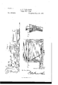
- FIG. 1 is a side elevation of a locomotive and tender with my invention shown as applied thereto.
- Fig. 2 is an enlarged central vertical longitudinal section of the condensing device proper within the tank of the tender.
- Fig. 3 is an enlarged sectional detail view of the valve.
- let-ter L designates the locomotive, and T the tender, the latter having a cold-water tank within its body, as is usual.
- E is an exhaustpipe leading from the cylinder C alongside the locomotive L and connected by a flexible pipe or piece of tubing F with the condenser proper, which is located within the tank of the tender, by which means v the steam as it is used in the cylinder is passed through the pipe E and flexible pipe F to the condenser proper.
- the latter is of the following spec-inc construction:
- valve-seat V is a pipe leading upwardly within the tank of the tender and having a conical portion forming a valve-seat V within its body, above which it is extended upward, as at U, to about the water-level in the tank, where its upper end is left open, and the rubber pipeF is connected to the lower end of this pipe P, whereby the exhauststealn will be caused to pass upwardly through the pipe.
- a correspondingly-shaped rubber valve R having longitudinal stems L, around which are placed coiled springs S, which bear at their outer ends against cross-bars B within the pipe P, as best seen in Fig. 3.
- I is an inlet-pipe arranged along ⁇ the bottom of the tank and having a number of openings O in its body, whereby cold water willbe admitted thereto, and this pipe is joined to the pipe P at the junction J above the valve R, as shown. Above this junction a wire screen I extends across the pipe P.
- the hereiirdescribed steam-condenser comprising an upright pipe located within a cold-water tank, connected at its lower end with the steameexhaust, open at its upper end within said tank, having a downwardly-closing valve within its body, a wire screen across said pipe above the valve, and an inlet-pipe leading from the bottom of the IOO tank upwardly into said pipe at a point between the valve and the screen therein, the whole operating substantially as and for the purpose set forth.
Landscapes
- Engineering & Computer Science (AREA)
- Mechanical Engineering (AREA)
- General Engineering & Computer Science (AREA)
- Engine Equipment That Uses Special Cycles (AREA)
Description
J HARTFORD' STEAM GONDENSER.
Patented'Deo. 16,. 18901.
Ima@ Jgfrd) UNITED STATES PATENT OFFICE..
ISAAC J. HARTFORD, OF KIRKSVILLE, MISSOURI.
STEAM-CONDENSER.
SPECIFICATION forming part of Letters Patent No. 442,885, dated December 16, 1890..
Application iiled July 24, 1890. Serial No. 359,790. (No model.)
To all whom t may concern.-
Be it known that l, ISAAC J. HARTFORD, a citizen of the United States, residing at Kirksville, in the county of Adair and State of Missouri, have invented a new and useful Steam-Condenser, of which the following isa specification.
This invention relates to steam-engines, and more particularly to that part thereof known as a condenser5 and the object of the invention is to effect improvements upon devices of this same general character heretofore existing.
To this end the invention consists in the speciiic details of construction hereinafter more fully described, and illustrated in the drawings, in which- Figure l is a side elevation of a locomotive and tender with my invention shown as applied thereto. Fig. 2 is an enlarged central vertical longitudinal section of the condensing device proper within the tank of the tender. Fig. 3 is an enlarged sectional detail view of the valve.
Referring to the said drawings, the let-ter L designates the locomotive, and T the tender, the latter having a cold-water tank within its body, as is usual.
E is an exhaustpipe leading from the cylinder C alongside the locomotive L and connected by a flexible pipe or piece of tubing F with the condenser proper, which is located within the tank of the tender, by which means v the steam as it is used in the cylinder is passed through the pipe E and flexible pipe F to the condenser proper. The latter is of the following spec-inc construction:
P is a pipe leading upwardly within the tank of the tender and having a conical portion forming a valve-seat V within its body, above which it is extended upward, as at U, to about the water-level in the tank, where its upper end is left open, and the rubber pipeF is connected to the lower end of this pipe P, whereby the exhauststealn will be caused to pass upwardly through the pipe. Within said conical valve-seat V is a correspondingly-shaped rubber valve R, having longitudinal stems L, around which are placed coiled springs S, which bear at their outer ends against cross-bars B within the pipe P, as best seen in Fig. 3.
I is an inlet-pipe arranged along` the bottom of the tank and having a number of openings O in its body, whereby cold water willbe admitted thereto, and this pipe is joined to the pipe P at the junction J above the valve R, as shown. Above this junction a wire screen I extends across the pipe P.
The steam, flowing rearwardly through the exhaust-pipe E, flexible pipe F, and condenserpipe P, raises the valve R against the tension of its springs S, passes around said valve upwardly by the junction J, through the screen IV, throughout the extension U, out of the upper end of the latter, and into the cold water within the tank. The condensation of the steam by reason of the surrounding body of cold water produces a partial vacuum within the extension U, and the upward flow of the steam out of the upper end of said extension also assists in setting up an inward current from the cold water within the tank, through the openings O into the inlet-pipe I, and through the junction J of the same with the extension U, where it joins the steam j ustbefore the screen I is reached. The water and steam in a mixed condition then pass through the wire screen,whereby the mixture is converted into spray or tine streams, and the latter pass out of the upper end of the extension U and fall overinto the water within the tank. In this manner the steam has every opportunity of becoming condensed, not only by the action of the cold water surrounding the pipe P, valve-case V, and extension U, but also by its mixture with. cold water at the junction J and by its separation into tine streams by means of the wire screen WV. When the engine ceases to operate, the water in the tank by its pressure, as well as the springs S, closes the valve R to its seat V, and for this reason does not pass through the exhaust-pipe E into the cylinder.
Having thus described my invention, what I claim is- 1. The hereiirdescribed steam-condenser, the same comprising an upright pipe located within a cold-water tank, connected at its lower end with the steameexhaust, open at its upper end within said tank, having a downwardly-closing valve within its body, a wire screen across said pipe above the valve, and an inlet-pipe leading from the bottom of the IOO tank upwardly into said pipe at a point between the valve and the screen therein, the whole operating substantially as and for the purpose set forth.
2. In a stea1n-eondenser, the combination, with the exhaust-pipe E, the upright pipe I), connected therewith and located within a cold-water tank, its upper end being open Within said tank, and a downwardly-elosing valve R Within said upright pipe, of a wire screen \Vaeross the upright pipe between the valve and the upper end of the pipe, the whole operating substantially as and for the purpose set forth.
3. In a steam-condenser, the combination, with the exhaust-pipe E, the uprightJ pipe I), Connected therewith and located Within a cold-Water tank, the oonioal valve-seat Y in said upright pipe, the extension U above said Valve-seat opening at its upper end Within the tank, and the wire screen XV across said extension, of the Cross-bars B within said pipe, the conical rubber valve R within said valveseat, provided with longitudinalstenis L, moving loosely through holes in said bars, springs S between said Valve and bars, and the inletpipe I, provided with openings O near one end which lies along the bottom of the tank, the other end of said inlet-pipe being ex tended upward and joined obliquely, as at J, to said extension U between the valve and screen, the Whole constructed and operating substantially as hereinbefore described.
' In testimony that I olaini the foregoing as presence of two witnesses.
ISAAC J. HARTFORD. Witnesses:
THEODORE BRIGHAM, J. I). MARKEY.
l l l l l l lny own I have hereto affixed my signature in 3 5
Publications (1)
| Publication Number | Publication Date |
|---|---|
| US442885A true US442885A (en) | 1890-12-16 |
Family
ID=2511780
Family Applications (1)
| Application Number | Title | Priority Date | Filing Date |
|---|---|---|---|
| US442885D Expired - Lifetime US442885A (en) | Steam-condenser |
Country Status (1)
| Country | Link |
|---|---|
| US (1) | US442885A (en) |
-
0
- US US442885D patent/US442885A/en not_active Expired - Lifetime
Similar Documents
| Publication | Publication Date | Title |
|---|---|---|
| US738486A (en) | Filter. | |
| US442885A (en) | Steam-condenser | |
| US548458A (en) | Means for automatically separating liquids from natural gas | |
| US303554A (en) | Stop-cock | |
| US740225A (en) | Strainer. | |
| US743006A (en) | Foot-valve. | |
| US480264A (en) | Boiler attachment | |
| US651964A (en) | Check-valve. | |
| US953040A (en) | Pressure-regulator. | |
| US514438A (en) | Tkk nattorat | |
| US600921A (en) | Steam-eliminator | |
| US923878A (en) | Valve for water-tanks. | |
| US425108A (en) | Steam-trap | |
| US319817A (en) | Inspirator | |
| US242495A (en) | Filtering apparatus | |
| US120269A (en) | Improvement in valves for steamboat engines | |
| US598630A (en) | Steam-separator | |
| US408919A (en) | Blow-off cock and fire-extinguisher | |
| US167550A (en) | Improvement in pump-valves | |
| US1252720A (en) | Steam-trap. | |
| US787453A (en) | Jet-pump. | |
| US578481A (en) | Self-reversing check-valve | |
| US780903A (en) | Check-valve. | |
| US310885A (en) | Steam-trap | |
| US326465A (en) | Feed-water alarm |