US4424471A - Electrical motor - Google Patents
Electrical motor Download PDFInfo
- Publication number
- US4424471A US4424471A US06/353,754 US35375482A US4424471A US 4424471 A US4424471 A US 4424471A US 35375482 A US35375482 A US 35375482A US 4424471 A US4424471 A US 4424471A
- Authority
- US
- United States
- Prior art keywords
- windings
- rotor
- main
- search
- winding
- Prior art date
- Legal status (The legal status is an assumption and is not a legal conclusion. Google has not performed a legal analysis and makes no representation as to the accuracy of the status listed.)
- Expired - Fee Related
Links
- 238000004804 winding Methods 0.000 claims abstract description 93
- 239000003990 capacitor Substances 0.000 claims description 3
- 230000003213 activating effect Effects 0.000 claims description 2
- 230000010355 oscillation Effects 0.000 description 3
- 230000004913 activation Effects 0.000 description 2
- 238000010276 construction Methods 0.000 description 2
- 238000010586 diagram Methods 0.000 description 2
- 230000007423 decrease Effects 0.000 description 1
- 230000000694 effects Effects 0.000 description 1
- 230000003993 interaction Effects 0.000 description 1
- 238000004519 manufacturing process Methods 0.000 description 1
- 230000000452 restraining effect Effects 0.000 description 1
Images

Classifications
-
- H—ELECTRICITY
- H02—GENERATION; CONVERSION OR DISTRIBUTION OF ELECTRIC POWER
- H02K—DYNAMO-ELECTRIC MACHINES
- H02K29/00—Motors or generators having non-mechanical commutating devices, e.g. discharge tubes or semiconductor devices
- H02K29/06—Motors or generators having non-mechanical commutating devices, e.g. discharge tubes or semiconductor devices with position sensing devices
- H02K29/12—Motors or generators having non-mechanical commutating devices, e.g. discharge tubes or semiconductor devices with position sensing devices using detecting coils using the machine windings as detecting coil
Definitions
- This invention relates to electrical motors.
- Conventional direct-current motors include a rotor, carrying a plurality of magnetic poles, and a stator, carrying at least two main windings which, when activated interact with the magnetic field produced by the magnetic poles to drive the rotor relative to the stator.
- Switching means in the form of a commutator and brushes is required to change the state of activation of the main windings in accordance with the rotational position of the rotor so that the rotor continues to rotate in one direction.
- an electrical motor comprising a rotor carrying a plurality of permanent magnetic poles, a stator carrying at least two main windings which, when activated, interact with the magnetic field generated by the said poles to drive the rotor relative to the stator, and electronic switching means for activating the main windings in sequence in accordance with the rotational position of the rotor characterised in that the electronic switching means comprises search windings on the stator each associated with a respective one of the main windings and arranged to interact with the magnetic field generated by the said poles, and switches for each main winding operable by the search winding associated therewith to activate the main windings for different periods.
- the main windings are energised for different periods, the rotational force produced by the main windings is different. It is therefore possible, by matching the energisation periods of the main windings to the inertia of the rotor, to ensure that the rotor always commences rotation in the same direction.
- each switch preferably comprise switch circuits incorporating transistors.
- each switch may comprise a power transistor for conducting current through the main winding, and a drive transistor for controlling the conductive state of the transistor.
- the differences in activation of the main windings is conveniently achieved by connecting the search windings into a switch circuit having a different time constant.
- each switch is preferably operable in response to current induced in the search winding by the main winding. Additionally, the main winding preferably occupies unequal parts of the circumferential length of the stator.
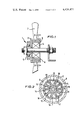
- FIG. 1 is an axial cross-section through a fan incorporating an electric motor in accordance with the invention
- FIG. 2 is a radial cross-section through the fan of FIG. 1, taken along the line II--II;
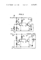
- FIG. 3 is a circuit diagram of the rotor incorporated in the fan of FIGS. 1 and 2;
- FIGS. 4 and 5 are diagrams indicating the state energisation of the rotor in two different rotational positions.
- an electric motor indicated generally at 1, comprises a rotor 2 which carries a set of fan blades 3.
- the rotor 2 is rotatably mounted on a stator 4 by means of a single bearing race 5.
- the rotor 2 carries a plurality (in this case two) of permanent magnets 6, 6 disposed circumferentially around the stator 4.
- One of the magents 6 has a North pole piece facing the rotor, the other having a South pole piece facing the rotor.
- the stator 4 is of conventional laminated construction, with windings 10 located in five pairs of radially opposed slots 11 to 20.
- the windings 10 are divided into four groups.
- a first main winding 22 (FIG. 3) occupies two adjacent pairs of opposite slots 11,12, 16 and 17.
- a first search winding 25 occupies the same slots as the first main winding 22, and a second search winding 26 occupies the same slots as the second main winding 23.
- the main windings 22,23 and the search windings 25,26 are electrically interconnected by the circuit illustrated in FIG. 3.
- a voltage V is supplied to the circuit by a DC voltage source along positive and negative lines 30,31.
- the voltage across the supply lines 30,31 is divided by first and second resistors R 1 and R 2 .
- the dividing point 33 between the two resistors R 1 and R 2 is connected to the base of a drive transistor T 1 of the N-P-N type, the collector of which is connected to the positive supply line 30 through a third resistor R 3 , the emitter of the drive transistor T 1 being connected to the negative supply line 31.
- the junction between the third resistor R 3 and the collector of the drive transistor T 1 is connected to the base of an N-P-N power transistor T 2 the collector of which is connected to one side of the first main winding 22, the other side of the first main winding 22 being connected to the positive supply line 30.
- the emitter of the power transistor T.sub. 2 is connected to the negative supply line 31.
- One side of the search winding is connected to the negative supply line 31 via a diode 35.
- the other side of the search winding 25 is connected to the dividing point 33 between the two resistors R 1 and R 2 via a biasing resistor R 4 .
- the second main winding 23 and the second search winding 26 are connected to the supply lines 30,31 in a manner similar to the first main and search windings 22,25, as illustrated in the lower part of FIG. 3, similar components being identified by the reference numerals. That part of the circuit for the second main and search windings differs from that for the first windings in that the bias resistor R 4 is omitted and the second search winding is connected in parallel with a capacitor C.
- the diodes 35 prevent the resulting reverse currents generated in the search windings 25,26 from being transmitted to the drive transistors T 1 .
- the potential at the bases of the drive transistors therefore drop so that the drive transistors T 1 also cease conducting. This increases the potential at the bases of the power transistors T 2 so that they start to conduct once again. The sequence of events is therefore repeated.
- the search windings 25,26 and the associated transistors T 1 ,T 2 therefore act as switch circuits for the main windings 22,23 and cause the magnetic fields produced by the main windings to rise and fall in phase with each other.
- the duration of the magnetic fields produced by each main winding will depend upon the period for which the drive transistors T 1 are held in a conducting state. This period differs for the two drive transistors T 1 because the capacitor C increases the time constant of the circuit incorporating the second search winding 26, whilst the bias resistor R decreases the time constant of the current incorporating the first search winding 25.
- FIGS. 4 and 5 schematically illustrate the motor 1 in two starting positions and the respective polarities of the main windings 22,23. In the positions illustrated, repulsion between the magnetic field produced by the main windings is at a minimum in FIG. 4 and a maximum in FIG. 5.
- FIG. 4 when the motor is switched on, the rotor is subjected to a slight rotational movement as a result of the disposition of the first main winding 22 over a greater circumferential length of the rotor than the second main winding 23.
- the search coils operate under the influence of the magnets in the rotor to actuate the main windings 22,23 each time the search coils are swept by the magnets 6 on the rotor so that the rotor accelerates to a maximum operating speed.
- the rotor would be equally likely to commence rotation in either direction.
- the time constants of the switch circuits controlling the main windings 22,23 are different. Hence the restraining forces exerted on the rotor by the second main windings are greater than those exerted by the first main windings.
- the operation of the circuit is similar for the starting position illustrated in FIG. 5.
- initial movement of the rotor from the unstable equilibrium position shown causes the rotor to move towards the position illustrated in FIG. 4 with a consequent increase in the current in the main windings 22,23. Thereafter the rotor operates in the manner previously described.
- the embodiment of the invention described above is provided with only two main windings, the invention is equally applicable to motors incorporating three or more main windings.
- the initial oscillations of the rotor during starting would extend over a correspondingly shorter angular distance, thereby reducing start-up time.
- the rotor and stator may be constructed as parallel discs so that the length of the motor may be reduced.
Landscapes
- Engineering & Computer Science (AREA)
- Power Engineering (AREA)
- Control Of Motors That Do Not Use Commutators (AREA)
Abstract
Description
Claims (1)
Applications Claiming Priority (2)
| Application Number | Priority Date | Filing Date | Title |
|---|---|---|---|
| GB8102562A GB2065439B (en) | 1977-12-02 | 1978-11-30 | Crop harvesting machines |
| GB8102562 | 1981-03-10 |
Publications (1)
| Publication Number | Publication Date |
|---|---|
| US4424471A true US4424471A (en) | 1984-01-03 |
Family
ID=10519285
Family Applications (1)
| Application Number | Title | Priority Date | Filing Date |
|---|---|---|---|
| US06/353,754 Expired - Fee Related US4424471A (en) | 1978-11-30 | 1982-03-01 | Electrical motor |
Country Status (1)
| Country | Link |
|---|---|
| US (1) | US4424471A (en) |
Cited By (2)
| Publication number | Priority date | Publication date | Assignee | Title |
|---|---|---|---|---|
| US5053686A (en) * | 1987-11-18 | 1991-10-01 | Halsall Products Limited | Direct current brushless motor for fans, pumps and similar equipments |
| US20110025253A1 (en) * | 2007-08-14 | 2011-02-03 | Krishnan Ramu | Single Switch Controlled Switched Reluctance Machine |
Citations (4)
| Publication number | Priority date | Publication date | Assignee | Title |
|---|---|---|---|---|
| US3264339A (en) | 1964-05-05 | 1966-08-02 | Standard Oil Co | Process for the preparation of s-(2-hydroxyalkyl) and s-(2-mercaptoalkyl) esters |
| US3402333A (en) | 1967-09-08 | 1968-09-17 | Sanders Associates Inc | Electronically controlled synchronous motor |
| US3662237A (en) | 1966-11-11 | 1972-05-09 | Robert Favre | Commutated motor including commutation means responsive to reactive voltage induced in armature windings |
| US4286198A (en) | 1978-05-11 | 1981-08-25 | Valbrev S.A.R.L. | Direct current motor unit without commutator |
-
1982
- 1982-03-01 US US06/353,754 patent/US4424471A/en not_active Expired - Fee Related
Patent Citations (4)
| Publication number | Priority date | Publication date | Assignee | Title |
|---|---|---|---|---|
| US3264339A (en) | 1964-05-05 | 1966-08-02 | Standard Oil Co | Process for the preparation of s-(2-hydroxyalkyl) and s-(2-mercaptoalkyl) esters |
| US3662237A (en) | 1966-11-11 | 1972-05-09 | Robert Favre | Commutated motor including commutation means responsive to reactive voltage induced in armature windings |
| US3402333A (en) | 1967-09-08 | 1968-09-17 | Sanders Associates Inc | Electronically controlled synchronous motor |
| US4286198A (en) | 1978-05-11 | 1981-08-25 | Valbrev S.A.R.L. | Direct current motor unit without commutator |
Cited By (3)
| Publication number | Priority date | Publication date | Assignee | Title |
|---|---|---|---|---|
| US5053686A (en) * | 1987-11-18 | 1991-10-01 | Halsall Products Limited | Direct current brushless motor for fans, pumps and similar equipments |
| US20110025253A1 (en) * | 2007-08-14 | 2011-02-03 | Krishnan Ramu | Single Switch Controlled Switched Reluctance Machine |
| US8674648B2 (en) * | 2007-08-14 | 2014-03-18 | Regal Beloit America, Inc. | Single switch controlled switched reluctance machine |
Similar Documents
| Publication | Publication Date | Title |
|---|---|---|
| EP0040484B1 (en) | Brushless d.c. motors | |
| US4510422A (en) | DC Motor soft-start circuit | |
| US4030005A (en) | Brushless d.c. motor having rotor position-dependent control means | |
| US4707645A (en) | Single-phase brushless motor | |
| US3916272A (en) | Speed control for an electronic commutated d-c motor | |
| US4949023A (en) | Direct current machine with switchable stator windings | |
| EP0223093B1 (en) | Brushless motor | |
| US4748388A (en) | Brushless d.c. motor having RC time-delay stage(s) and driver transistors which prevent simultaneous conduction by the power transistors of the wound conductor pair(s) of the motor winding | |
| US4282464A (en) | Reversible drive circuit for brushless DC motor | |
| JPS6039356A (en) | Brushless field reversing dc fan motor | |
| US3214663A (en) | Semiconductor commutated motor system with capacitive pickup | |
| US3969658A (en) | Motor and control system having cyclic reversal and unidirectional capabilities | |
| US3483456A (en) | Brushless direct-current motor with hall-generator control | |
| GB2215527A (en) | Stable start position for brushless D.C. electric motor | |
| US4035712A (en) | Electrical generating apparatus | |
| KR930005316A (en) | Brushless induction synchronous motor | |
| US3204165A (en) | Self-commutating direct current electric motor | |
| CA1096439A (en) | Rotor short-circuiting switch | |
| US3281629A (en) | Control system for sequentially energizing motor phase windings | |
| US3504252A (en) | Speed-controlled d.c. motor having a mechanical or electrical commutator | |
| US3766456A (en) | Rotating electrical machine | |
| US3456174A (en) | Direct current motor with transistorized power supply | |
| US4424471A (en) | Electrical motor | |
| US3364407A (en) | Brushless direct current motor | |
| EP0060143B1 (en) | Electrical motor |
Legal Events
| Date | Code | Title | Description |
|---|---|---|---|
| AS | Assignment |
Owner name: FORD MOTOR COMPANY, DEARBORN, MI A CORP. OF DE Free format text: ASSIGNMENT OF ASSIGNORS INTEREST.;ASSIGNOR:COLLEN, JOHN W.;REEL/FRAME:004021/0923 Effective date: 19820216 Owner name: FORD MOTOR COMPANY, A CORP. OF DE, MICHIGAN Free format text: ASSIGNMENT OF ASSIGNORS INTEREST;ASSIGNOR:COLLEN, JOHN W.;REEL/FRAME:004021/0923 Effective date: 19820216 |
|
| MAFP | Maintenance fee payment |
Free format text: PAYMENT OF MAINTENANCE FEE, 4TH YEAR, PL 96-517 (ORIGINAL EVENT CODE: M170); ENTITY STATUS OF PATENT OWNER: LARGE ENTITY Year of fee payment: 4 |
|
| MAFP | Maintenance fee payment |
Free format text: PAYMENT OF MAINTENANCE FEE, 8TH YEAR, PL 96-517 (ORIGINAL EVENT CODE: M171); ENTITY STATUS OF PATENT OWNER: LARGE ENTITY Year of fee payment: 8 |
|
| FEPP | Fee payment procedure |
Free format text: MAINTENANCE FEE REMINDER MAILED (ORIGINAL EVENT CODE: REM.); ENTITY STATUS OF PATENT OWNER: LARGE ENTITY |
|
| LAPS | Lapse for failure to pay maintenance fees | ||
| FP | Lapsed due to failure to pay maintenance fee |
Effective date: 19960103 |
|
| STCH | Information on status: patent discontinuation |
Free format text: PATENT EXPIRED DUE TO NONPAYMENT OF MAINTENANCE FEES UNDER 37 CFR 1.362 |