EP0060143B1 - Electrical motor - Google Patents
Electrical motor Download PDFInfo
- Publication number
- EP0060143B1 EP0060143B1 EP19820301215 EP82301215A EP0060143B1 EP 0060143 B1 EP0060143 B1 EP 0060143B1 EP 19820301215 EP19820301215 EP 19820301215 EP 82301215 A EP82301215 A EP 82301215A EP 0060143 B1 EP0060143 B1 EP 0060143B1
- Authority
- EP
- European Patent Office
- Prior art keywords
- windings
- rotor
- main
- search
- winding
- Prior art date
- Legal status (The legal status is an assumption and is not a legal conclusion. Google has not performed a legal analysis and makes no representation as to the accuracy of the status listed.)
- Expired
Links
Images


Classifications
-
- H—ELECTRICITY
- H02—GENERATION; CONVERSION OR DISTRIBUTION OF ELECTRIC POWER
- H02K—DYNAMO-ELECTRIC MACHINES
- H02K29/00—Motors or generators having non-mechanical commutating devices, e.g. discharge tubes or semiconductor devices
- H02K29/06—Motors or generators having non-mechanical commutating devices, e.g. discharge tubes or semiconductor devices with position sensing devices
- H02K29/12—Motors or generators having non-mechanical commutating devices, e.g. discharge tubes or semiconductor devices with position sensing devices using detecting coils using the machine windings as detecting coil
Definitions
- This invention relates to electrical motors.
- Conventional direct-current motors include a rotor, carrying a plurality of magnetic poles, and a stator, carrying at least two main windings which, when activated interact with the magnetic field produced by the magnetic poles to drive the rotor relative to the stator.
- Switching means in the form of a commutator and brushes is required to change the state of activation of the main windings in accordance with the rotational position of the rotor so that the rotor continues to rotate in one direction.
- US-A-3,377,535 discloses a brushless direct-current motor in which the rotor is also provided with search windings, each of which is associated with a respective one of the main windings.
- the current induced therein by their interaction with the magnetic field produced by the magnetic poles is used to control switches which activate the main windings in sequence in accordance with the rotational position of the rotor.
- Such motors suffer from the disadvantage that rotation is equally likely to start in one direction as the other. This can be a disadvantage where the motor is used to operate, for example, a fan.
- an electrical motor comprising a rotor carrying a plurality of permanent magnetic poles, a stator carrying at least two main windings which, when activated, interact with the magnetic fields generated by the said poles to drive the rotor relative to the stator, search windings on the stator each associated with a respective one of the main windings and arranged to interact with the magnetic field generated by the said poles and switches for each main winding operable by the search winding associated therewith to activate the main windings in sequence in accordance with the rotation of the rotor, characterised in that the switches activate the main windings for different relative durations during each of their respective operating cycles.
- the main windings are energised for different periods, the rotational force produced by the main windings is different. It is therefore possible, by matching the energisation periods of the main windings to the inertia of the rotor, to ensure that the rotor always commences rotation in the same direction.
- each switch preferably comprise switch circuits incorporating transistors.
- each switch may comprise a power transistor for conducting current through the main winding, and a drive transistor for controlling the conductive state of the transistor.
- the differences in activation of the main windings is conveniently achieved by connecting the search windings into a switch circuit having a different time constant.
- each switch is preferably operable in response to current induced in the search winding by the main winding. Additionally, the main windings preferably occupy unequal parts of the circumferential length of the stator.
- an electric motor indicated generally at 1, comprises a rotor 2 which carries a set of fan blades 3.
- the rotor 2 is rotatably mounted on a stator 4 by means of a single bearing race 5.
- the rotor 2 carries a plurality (in this case two) of permanent magnets 6, 6 disposed circumferentially around the stator 4.
- One of the magnets 6 has a North pole piece facing the rotor, the other having a South pole piece facing the rotor.
- the stator 4 is of conventional laminated construction, with windings 10 located in five pairs of radially opposed slots 11 to 20.
- the windings 10 are divided into four groups.
- a first, main winding 22 (Figure 3) occupies two adjacent pairs of opposite slots 11, 12, 16 and 17.
- a second main winding 23 ( Figure 3) occupies three adjacent pairs of opposite slots 13 to 15 and 18 to 20 at 90° to those occupied by the first main winding 22.
- a first search winding 25 occupies the same slots as the first main winding 22, and a second search winding 26 occupies the same slots as the second main winding 23.
- the main windings 22, 23 and the search windings 25, 26 are electrically interconnected by the circuit illustrated in Figure 3.
- a voltage V is supplied to the circuit by a DC voltage source along positive and negative lines 30, 31.
- the voltage across the supply lines 30, 31 is divided by first and second resistors R, and R 2 .
- the dividing point 33 between the two resistors R, and R 2 is connected to the base of a drive transistor T, of the N-P-N type, the collector of which is connected to the positive supply line 30 through a third resistor R 3 , the emitter of the drive transistor T 1 being connected to the negative supply line 31.
- the junction between the third resistor R 3 and the collector of the drive transistor T 1 is connected to the base of an N-P-N power transistor T 2 the collector of which is connected to one side of the first main winding 22, the other side of the first main winding 22 being connected to the positive supply line 30.
- the emitter of the power transistor T 2 is connected to the negative supply line 31.
- One side of the search winding is connected to the negative supply line 31 via a diode 35.
- the other side of the search winding 25 is connected to the dividing point 33 between the two resistors R, and R 2 via a biasing resistor R 4 .
- the second main winding 23 and the second search winding 26 are connected to the supply lines 30, 31 in a manner similar to the first main and search windings 22, 25, as illustrated in the lower part of Figure 3, similar components being identified by the reference numerals. That part of the circuit for the second main and search windings differs from that for the first windings in that the bias resistor R 4 is omitted and the second search winding is connected in parallel with a capacitor C.
- the diodes 35 prevent the resulting reverse currents generated in the search windings 25, 26 from being transmitted to the drive transistors T,.
- the potential at the bases of the drive transistors therefore drop so that the drive transistors T, also cease conducting. This increases the potential at the bases of the power transistors T 2 so that they start to conduct once again. The sequence of events is therefore repeated.
- the search windings 25, 26 and the associated transistors T i , T 2 therefore act as switch circuits for the main windings 22, 23 and cause the magnetic fields produced by the main windings to rise and fall cylindrically.
- the duration of the magnetic fields produced by each main winding will depend upon the period for which the drive transistors T, are held in a conducting state. This period differs for the two drive transistors T, because the capacitor C increases the time constant of the circuit incorporating the second search winding 26, whilst the bias resistor R 4 decreases the time constant of the current incorporating the first search winding 25.
- FIGs 4 and 5 schematically illustrate the motor 1 in two starting positions and the respective polarities of the main windings 25, 26. In the positions illustrated, repulsion between the magnetic field produced by the main windings is at a minimum in Figure 4 and a maximum in Figure 5.
- Figure 4 if, when the motor is switched on, the rotor were to move slightly clockwise out of the equilibrium position, the pulsating magnetic field established by the main windings would apply an anti-clockwise restoring force on the rotor tending to return it to its equilibrium position. Any initial movement of the rotor therefore results in an oscillation of the rotor about its equilibrium point.
- the search coils operate under the influence of the magnets in the rotor to actuate the main windings 22, 23 each time the search coils are swept by the magnets 6 on the rotor so that the rotor accelerates to a maximum operating speed.
- the rotor would be equally likely to commence rotation in either direction.
- the time constants of the switch circuits controlling the main windings 22, 23 are different. Hence the restoring forces exerted on the rotor by the second main windings are greater than those exerted by the first main windings.
- the embodiment of the invention described above is provided with only two main windings, the invention is equally applicable to motors incorporating three or more main windings.
- the initial oscillations of the rotor during starting would extend over a correspondingly shorter angular distance, thereby reducing start-up time.
- the rotor and stator may be constructed as parallel discs so that the length of the motor may be reduced.
Description
- This invention relates to electrical motors.
- Conventional direct-current motors include a rotor, carrying a plurality of magnetic poles, and a stator, carrying at least two main windings which, when activated interact with the magnetic field produced by the magnetic poles to drive the rotor relative to the stator. Switching means in the form of a commutator and brushes is required to change the state of activation of the main windings in accordance with the rotational position of the rotor so that the rotor continues to rotate in one direction.
- It has previously been proposed to replace the conventional commutator and brushes with electronic switching means such as a Hall generator (see, for example, GB-A-1,269,434). This avoids the manufacturing problems associated with commutators and brushes. However, Hall generators are relatively expensive.
- US-A-3,377,535 discloses a brushless direct-current motor in which the rotor is also provided with search windings, each of which is associated with a respective one of the main windings. The current induced therein by their interaction with the magnetic field produced by the magnetic poles is used to control switches which activate the main windings in sequence in accordance with the rotational position of the rotor. However, such motors suffer from the disadvantage that rotation is equally likely to start in one direction as the other. This can be a disadvantage where the motor is used to operate, for example, a fan.
- According to the present invention there is provided an electrical motor comprising a rotor carrying a plurality of permanent magnetic poles, a stator carrying at least two main windings which, when activated, interact with the magnetic fields generated by the said poles to drive the rotor relative to the stator, search windings on the stator each associated with a respective one of the main windings and arranged to interact with the magnetic field generated by the said poles and switches for each main winding operable by the search winding associated therewith to activate the main windings in sequence in accordance with the rotation of the rotor, characterised in that the switches activate the main windings for different relative durations during each of their respective operating cycles.
- Since the main windings are energised for different periods, the rotational force produced by the main windings is different. It is therefore possible, by matching the energisation periods of the main windings to the inertia of the rotor, to ensure that the rotor always commences rotation in the same direction.
- The switches preferably comprise switch circuits incorporating transistors. For example, each switch may comprise a power transistor for conducting current through the main winding, and a drive transistor for controlling the conductive state of the transistor.
- The differences in activation of the main windings is conveniently achieved by connecting the search windings into a switch circuit having a different time constant.
- To assist in a rapid start up of the motor each switch is preferably operable in response to current induced in the search winding by the main winding. Additionally, the main windings preferably occupy unequal parts of the circumferential length of the stator.
- A preferred embodiment of the invention will now be described, by way of example only, with reference to the accompanying drawings, in which:
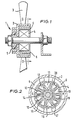
- Figure 1 is an axial cross-section through a fan incorporating an electric motor in accordance with the invention;
- Figure 2 is a radial cross-section through the fan of Figure 1, taken along the line II-II;
- Figure 3 is a circuit diagram of the stator incorporated in the fan of Figures 1 and 2; and
- Figures 4 and 5 are diagrams indicating the state energisation of the rotor in two different rotational positions.
- Referring to the drawings, an electric motor, indicated generally at 1, comprises a
rotor 2 which carries a set offan blades 3. Therotor 2 is rotatably mounted on a stator 4 by means of a single bearingrace 5. Therotor 2 carries a plurality (in this case two) ofpermanent magnets magnets 6 has a North pole piece facing the rotor, the other having a South pole piece facing the rotor. - The stator 4 is of conventional laminated construction, with
windings 10 located in five pairs of radially opposedslots 11 to 20. - The
windings 10 are divided into four groups. A first, main winding 22 (Figure 3) occupies two adjacent pairs ofopposite slots opposite slots 13 to 15 and 18 to 20 at 90° to those occupied by the firstmain winding 22. - A first search winding 25 (Figure 3) occupies the same slots as the first main winding 22, and a second search winding 26 occupies the same slots as the second main winding 23.
- The
main windings search windings - Considering the first
main winding 22 and the first search winding 25, as illustrated in the upper part of Figure 3, a voltage V is supplied to the circuit by a DC voltage source along positive andnegative lines supply lines point 33 between the two resistors R, and R2 is connected to the base of a drive transistor T, of the N-P-N type, the collector of which is connected to thepositive supply line 30 through a third resistor R3, the emitter of the drive transistor T1 being connected to thenegative supply line 31. The junction between the third resistor R3 and the collector of the drive transistor T1 is connected to the base of an N-P-N power transistor T2 the collector of which is connected to one side of the firstmain winding 22, the other side of the firstmain winding 22 being connected to thepositive supply line 30. The emitter of the power transistor T2 is connected to thenegative supply line 31. - One side of the search winding is connected to the
negative supply line 31 via adiode 35. The other side of the search winding 25 is connected to the dividingpoint 33 between the two resistors R, and R2 via a biasing resistor R4. - The second main winding 23 and the second search winding 26 are connected to the
supply lines search windings - In operation, when the motor 1 is switched on, the positive voltage at the base of each drive transistor T, is low, so that the drive transistors do not conduct. The positive voltage applied to the bases of the power transistors T2 are, however, high, so that they are conductive. Current therefore flows through the
main windings main windings search windings main windings diodes 35 prevent the resulting reverse currents generated in thesearch windings search windings main windings - The duration of the magnetic fields produced by each main winding will depend upon the period for which the drive transistors T, are held in a conducting state. This period differs for the two drive transistors T, because the capacitor C increases the time constant of the circuit incorporating the second search winding 26, whilst the bias resistor R4 decreases the time constant of the current incorporating the first search winding 25.
- The magnetic fields generated in the
main windings magnets 6 to rotate the rotor 4. Figures 4 and 5 schematically illustrate the motor 1 in two starting positions and the respective polarities of themain windings - As the rotor rotates, the search coils operate under the influence of the magnets in the rotor to actuate the
main windings magnets 6 on the rotor so that the rotor accelerates to a maximum operating speed. - If the circuits incorporating the first and second windings were identical, the rotor would be equally likely to commence rotation in either direction. In the present rotor however, the time constants of the switch circuits controlling the
main windings - The operation of the circuit is similar for the starting position illustrated in Figure 5. In this starting position, initial movement of the rotor from the unstable equilibrium position shown causes the rotor to move towards the position illustrated in Figure 4 with a consequent increase in the current in the
main windings - Although the embodiment of the invention described above is provided with only two main windings, the invention is equally applicable to motors incorporating three or more main windings. In such a construction, the initial oscillations of the rotor during starting would extend over a correspondingly shorter angular distance, thereby reducing start-up time.
- Additionally, the rotor and stator may be constructed as parallel discs so that the length of the motor may be reduced.
Claims (6)
Applications Claiming Priority (2)
| Application Number | Priority Date | Filing Date | Title |
|---|---|---|---|
| GB8107562A GB2094559A (en) | 1981-03-10 | 1981-03-10 | Electrical motor |
| GB8107562 | 1981-03-10 |
Publications (2)
| Publication Number | Publication Date |
|---|---|
| EP0060143A1 EP0060143A1 (en) | 1982-09-15 |
| EP0060143B1 true EP0060143B1 (en) | 1985-06-05 |
Family
ID=10520296
Family Applications (1)
| Application Number | Title | Priority Date | Filing Date |
|---|---|---|---|
| EP19820301215 Expired EP0060143B1 (en) | 1981-03-10 | 1982-03-10 | Electrical motor |
Country Status (3)
| Country | Link |
|---|---|
| EP (1) | EP0060143B1 (en) |
| DE (1) | DE3263996D1 (en) |
| GB (1) | GB2094559A (en) |
Families Citing this family (2)
| Publication number | Priority date | Publication date | Assignee | Title |
|---|---|---|---|---|
| GB8307047D0 (en) * | 1983-03-15 | 1983-04-20 | Hill R J | Stepping motors and drive circuits |
| DE19614755A1 (en) * | 1996-04-16 | 1997-10-23 | Pm Dm Gmbh | Multi-phase, brushless DC motor |
Family Cites Families (3)
| Publication number | Priority date | Publication date | Assignee | Title |
|---|---|---|---|---|
| GB1066036A (en) * | 1962-10-25 | 1967-04-19 | Matsushita Electric Ind Co Ltd | Method for controlling speed of a motor of brushless type |
| DE1613286A1 (en) * | 1967-11-10 | 1971-03-25 | Licentia Gmbh | DC miniature motor with permanent magnet rotor |
| DE1763295A1 (en) * | 1968-04-30 | 1972-01-05 | Philips Nv | Starting circuit for a brushless direct current motor |
-
1981
- 1981-03-10 GB GB8107562A patent/GB2094559A/en not_active Withdrawn
-
1982
- 1982-03-10 DE DE8282301215T patent/DE3263996D1/en not_active Expired
- 1982-03-10 EP EP19820301215 patent/EP0060143B1/en not_active Expired
Also Published As
| Publication number | Publication date |
|---|---|
| EP0060143A1 (en) | 1982-09-15 |
| GB2094559A (en) | 1982-09-15 |
| DE3263996D1 (en) | 1985-07-11 |
Similar Documents
| Publication | Publication Date | Title |
|---|---|---|
| EP0040484B1 (en) | Brushless d.c. motors | |
| US4510422A (en) | DC Motor soft-start circuit | |
| US4949023A (en) | Direct current machine with switchable stator windings | |
| US5491398A (en) | Repulsion motor | |
| US4707645A (en) | Single-phase brushless motor | |
| US4030005A (en) | Brushless d.c. motor having rotor position-dependent control means | |
| EP0223093B1 (en) | Brushless motor | |
| EP0140461A1 (en) | Simple brushless dc fan motor with reversing field | |
| US4748388A (en) | Brushless d.c. motor having RC time-delay stage(s) and driver transistors which prevent simultaneous conduction by the power transistors of the wound conductor pair(s) of the motor winding | |
| KR960006216A (en) | Dynamo Electric Machinery and its starting method | |
| EP0210047A3 (en) | Motor control and operation | |
| US3483456A (en) | Brushless direct-current motor with hall-generator control | |
| US3969658A (en) | Motor and control system having cyclic reversal and unidirectional capabilities | |
| US20040183308A1 (en) | Gas turbine engine starter generator that selectively changes the number of rotor poles | |
| GB2215527A (en) | Stable start position for brushless D.C. electric motor | |
| KR20010079877A (en) | Syncronous motor | |
| US3204165A (en) | Self-commutating direct current electric motor | |
| CA1096439A (en) | Rotor short-circuiting switch | |
| KR930005316A (en) | Brushless induction synchronous motor | |
| US3281629A (en) | Control system for sequentially energizing motor phase windings | |
| US3475668A (en) | Control circuit for a commutatorless d.c. motor | |
| US3504252A (en) | Speed-controlled d.c. motor having a mechanical or electrical commutator | |
| EP0060143B1 (en) | Electrical motor | |
| US3456174A (en) | Direct current motor with transistorized power supply | |
| US4424471A (en) | Electrical motor |
Legal Events
| Date | Code | Title | Description |
|---|---|---|---|
| PUAI | Public reference made under article 153(3) epc to a published international application that has entered the european phase |
Free format text: ORIGINAL CODE: 0009012 |
|
| AK | Designated contracting states |
Designated state(s): DE FR GB |
|
| 17P | Request for examination filed |
Effective date: 19821014 |
|
| GRAA | (expected) grant |
Free format text: ORIGINAL CODE: 0009210 |
|
| AK | Designated contracting states |
Designated state(s): DE FR GB |
|
| REF | Corresponds to: |
Ref document number: 3263996 Country of ref document: DE Date of ref document: 19850711 |
|
| ET | Fr: translation filed | ||
| PLBI | Opposition filed |
Free format text: ORIGINAL CODE: 0009260 |
|
| 26 | Opposition filed |
Opponent name: SIEMENS AKTIENGESELLSCHAFT, BERLIN UND MUENCHEN Effective date: 19860303 |
|
| PG25 | Lapsed in a contracting state [announced via postgrant information from national office to epo] |
Ref country code: DE Effective date: 19880203 |
|
| GBPC | Gb: european patent ceased through non-payment of renewal fee | ||
| PG25 | Lapsed in a contracting state [announced via postgrant information from national office to epo] |
Ref country code: FR Free format text: LAPSE BECAUSE OF NON-PAYMENT OF DUE FEES Effective date: 19881130 |
|
| REG | Reference to a national code |
Ref country code: FR Ref legal event code: ST |
|
| PGFP | Annual fee paid to national office [announced via postgrant information from national office to epo] |
Ref country code: GB Payment date: 19890310 Year of fee payment: 8 |
|
| RDAG | Patent revoked |
Free format text: ORIGINAL CODE: 0009271 |
|
| STAA | Information on the status of an ep patent application or granted ep patent |
Free format text: STATUS: PATENT REVOKED |
|
| 27W | Patent revoked |
Effective date: 19900515 |
|
| GBPR | Gb: patent revoked under art. 102 of the ep convention designating the uk as contracting state | ||
| APAH | Appeal reference modified |
Free format text: ORIGINAL CODE: EPIDOSCREFNO |