US4424426A - Battery powered drawer opening device - Google Patents
Battery powered drawer opening device Download PDFInfo
- Publication number
- US4424426A US4424426A US06/391,911 US39191182A US4424426A US 4424426 A US4424426 A US 4424426A US 39191182 A US39191182 A US 39191182A US 4424426 A US4424426 A US 4424426A
- Authority
- US
- United States
- Prior art keywords
- latch member
- mounting axis
- extended portion
- solenoid
- drawer
- Prior art date
- Legal status (The legal status is an assumption and is not a legal conclusion. Google has not performed a legal analysis and makes no representation as to the accuracy of the status listed.)
- Ceased
Links
- 230000008878 coupling Effects 0.000 claims 2
- 238000010168 coupling process Methods 0.000 claims 2
- 238000005859 coupling reaction Methods 0.000 claims 2
- 230000001154 acute effect Effects 0.000 description 1
- 230000004048 modification Effects 0.000 description 1
- 238000012986 modification Methods 0.000 description 1
Images

Classifications
-
- E—FIXED CONSTRUCTIONS
- E05—LOCKS; KEYS; WINDOW OR DOOR FITTINGS; SAFES
- E05B—LOCKS; ACCESSORIES THEREFOR; HANDCUFFS
- E05B47/00—Operating or controlling locks or other fastening devices by electric or magnetic means
- E05B47/06—Controlling mechanically-operated bolts by electro-magnetically-operated detents
- E05B47/0607—Controlling mechanically-operated bolts by electro-magnetically-operated detents the detent moving pivotally or rotatively
-
- A—HUMAN NECESSITIES
- A47—FURNITURE; DOMESTIC ARTICLES OR APPLIANCES; COFFEE MILLS; SPICE MILLS; SUCTION CLEANERS IN GENERAL
- A47B—TABLES; DESKS; OFFICE FURNITURE; CABINETS; DRAWERS; GENERAL DETAILS OF FURNITURE
- A47B88/00—Drawers for tables, cabinets or like furniture; Guides for drawers
- A47B88/40—Sliding drawers; Slides or guides therefor
- A47B88/453—Actuated drawers
- A47B88/457—Actuated drawers operated by electrically-powered actuation means
-
- E—FIXED CONSTRUCTIONS
- E05—LOCKS; KEYS; WINDOW OR DOOR FITTINGS; SAFES
- E05B—LOCKS; ACCESSORIES THEREFOR; HANDCUFFS
- E05B47/00—Operating or controlling locks or other fastening devices by electric or magnetic means
- E05B47/0001—Operating or controlling locks or other fastening devices by electric or magnetic means with electric actuators; Constructional features thereof
- E05B47/0002—Operating or controlling locks or other fastening devices by electric or magnetic means with electric actuators; Constructional features thereof with electromagnets
-
- E—FIXED CONSTRUCTIONS
- E05—LOCKS; KEYS; WINDOW OR DOOR FITTINGS; SAFES
- E05B—LOCKS; ACCESSORIES THEREFOR; HANDCUFFS
- E05B65/00—Locks or fastenings for special use
- E05B65/46—Locks or fastenings for special use for drawers
- E05B65/461—Locks or fastenings for special use for drawers for cash drawers
-
- G—PHYSICS
- G07—CHECKING-DEVICES
- G07G—REGISTERING THE RECEIPT OF CASH, VALUABLES, OR TOKENS
- G07G1/00—Cash registers
- G07G1/0018—Constructional details, e.g. of drawer, printing means, input means
- G07G1/0027—Details of drawer or money-box
-
- E—FIXED CONSTRUCTIONS
- E05—LOCKS; KEYS; WINDOW OR DOOR FITTINGS; SAFES
- E05B—LOCKS; ACCESSORIES THEREFOR; HANDCUFFS
- E05B47/00—Operating or controlling locks or other fastening devices by electric or magnetic means
- E05B2047/0048—Circuits, feeding, monitoring
- E05B2047/0057—Feeding
- E05B2047/0058—Feeding by batteries
-
- E—FIXED CONSTRUCTIONS
- E05—LOCKS; KEYS; WINDOW OR DOOR FITTINGS; SAFES
- E05B—LOCKS; ACCESSORIES THEREFOR; HANDCUFFS
- E05B47/00—Operating or controlling locks or other fastening devices by electric or magnetic means
- E05B2047/0048—Circuits, feeding, monitoring
- E05B2047/0065—Saving energy
-
- E—FIXED CONSTRUCTIONS
- E05—LOCKS; KEYS; WINDOW OR DOOR FITTINGS; SAFES
- E05B—LOCKS; ACCESSORIES THEREFOR; HANDCUFFS
- E05B47/00—Operating or controlling locks or other fastening devices by electric or magnetic means
- E05B47/0001—Operating or controlling locks or other fastening devices by electric or magnetic means with electric actuators; Constructional features thereof
- E05B47/0002—Operating or controlling locks or other fastening devices by electric or magnetic means with electric actuators; Constructional features thereof with electromagnets
- E05B47/0003—Operating or controlling locks or other fastening devices by electric or magnetic means with electric actuators; Constructional features thereof with electromagnets having a movable core
- E05B47/0004—Operating or controlling locks or other fastening devices by electric or magnetic means with electric actuators; Constructional features thereof with electromagnets having a movable core said core being linearly movable
-
- E—FIXED CONSTRUCTIONS
- E05—LOCKS; KEYS; WINDOW OR DOOR FITTINGS; SAFES
- E05C—BOLTS OR FASTENING DEVICES FOR WINGS, SPECIALLY FOR DOORS OR WINDOWS
- E05C3/00—Fastening devices with bolts moving pivotally or rotatively
- E05C3/12—Fastening devices with bolts moving pivotally or rotatively with latching action
- E05C3/16—Fastening devices with bolts moving pivotally or rotatively with latching action with operating handle or equivalent member moving otherwise than rigidly with the latch
- E05C3/22—Fastening devices with bolts moving pivotally or rotatively with latching action with operating handle or equivalent member moving otherwise than rigidly with the latch the bolt being spring controlled
- E05C3/24—Fastening devices with bolts moving pivotally or rotatively with latching action with operating handle or equivalent member moving otherwise than rigidly with the latch the bolt being spring controlled in the form of a bifurcated member
Definitions
- the invention relates to cash drawers and more particularly to a cash drawer which may be opened by a battery operated latch.
- a battery driven automatic cash drawer opening arrangement The drawer may be opened with a remotely located push button.
- the invention includes a latching and solenoid arrangement which minimizes the electrical energy required to open the drawer and therefore minimizes drainage of the battery.
- the arrangement includes a latch member, such as a bar fixed to the drawer tray, engageable with a hook portion of a latch lever which is pivotally mounted to the casing, preferably on one side of an upwardly extending bracket. On the other side of the bracket is pivotally mounted a latch lever release arm. One end of the latch lever release arm is engageable with another end portion of the latch lever to hold the latch lever in such a rotational position as to retain the latch member in its hook portion.
- a first spring extending between the latch lever and the release arm biases the latch member and latch lever into engagement.
- a solenoid which may be actuated by a small battery through a push button switch is mounted to the casing at the rear interior portion thereof and is coupled to the release arm so as to rotate the release arm out of engagement with the latch lever when the solenoid is actuated.
- the first spring is connected between the latch lever and the release arm so as to rotate the latch lever so that its hook portion disengages from the latch member mounted to the cash drawer.
- a second spring is mounted between the casing and the drawer tray so as to urge the drawer tray out of the casing when the hook portion of the latch lever is disengaged from the latch member.
- another portion of the latch lever is slidingly engaged by the latch member to rotate the latch lever into engagement with the release arm when the drawer tray is pushed into the casing.
- the portion of the release arm which engages the latch lever projects at the one end in a direction parallel to the axis of rotation of the latch lever to provide a surface facing that axis which makes flush contact with an edge portion of the latch lever when the drawer tray is fully inserted into the casing.
- the angles of the engaging edge and surface of the latch lever and release arm, respectively, are such as to provide for a smooth and energy efficient disengagement of the latch lever from the latch member and release arm when the solenoid is energized, and yet a secure locking of the latch lever with the latch member and the release arm when the drawer is closed and the solenoid is not being energized.
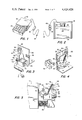
- FIG. 1 is a perspective view of the cash drawer in accordance with the present invention.
- FIG. 2 is a bottom view of a portion of the cash drawer shown in FIG. 1 with the bottom surface of the cash drawer casing removed for clarity;
- FIG. 3 is a perspective view of the remote control switch, batteries and one side of the latch assembly in accordance with the present invention
- FIG. 4 is a perspective view of the other side of the latch assembly in accordance with the present invention.
- FIG. 5 is a side view of the latch assembly in accordance with the present invention in a locked state with parts removed for clarity;
- FIG. 6 is a side view of the parts illustrated in FIG. 5 when the latch assembly is in an unlocked state with the latch assembly opening solenoid actuated;
- FIG. 7 is a side view of the parts illustrated in FIG. 5 in an unlatched state while the solenoid is not actuated;
- FIG. 8 is a side view of the elements shown in FIG. 5 while the cash drawer is being inserted into its casing.
- FIG. 1 there is shown a perspective view of a cash drawer 10 having a casing 12 for a drawer tray 14.
- the cash drawer is closed manually and may be opened with the aid of a remote control switch 16 coupled to a latching mechanism inside the cash drawer powered by a battery provided in a suitable battery case 18.
- terminal 20 of battery case 18 is electrically coupled to a solenoid 22 mounted to casing 12.
- Solenoid 22 is a component of a drawer latch assembly 24 for holding drawer tray 14 inside casing 12.
- a push spring 26 mounted between a rear portion of casing 12 and a rear panel of drawer tray 14 in order to urge the drawer tray 14 from casing 12 when the latch assembly 24 is in a state of disengagement.
- solenoid 22 is mounted in a casing 28 which is in turn fixed to one vertical side 30 of an L-shaped bracket 32 fixed to the base of casing 12.
- L-shaped bracket 32 pivotally supports latch members 34 and 36 of latch assembly 24 as will be described below.
- Latch member 34 is a latch lever release arm which is pivotally mounted to side 30 of bracket 32 and includes extended portions 38 and 40 extending vertically in opposite directions along parallel lines on opposite sides of its axis of rotation 41.
- the bottom end of the extended portion 38 has a pin 42 extending outwardly thereof pivotally mounted in a vertical slot 46 in solenoid plunger 44 which is mounted to solenoid casing 28 so as to be drawn inwardly of the solenoid when the solenoid 22 is energized. Accordingly, when solenoid 22 is energized, solenoid plunger 44 is drawn inwardly engaging pin 42 to rotate latch lever release arm 34 about its axis of rotation.
- An end portion 48 of extended portion 40 of latch lever release arm 34 extends in a direction opposite that of pin 42 through an opening 50 in bracket 32 to engage a portion of latch lever 36 as will be described.
- latch lever 36 is pivotally mounted to the opposite side 50 of bracket 32 for rotation about an axis of rotation 51 parallel to axis 41 of latch lever release arm 34.
- Latch lever 36 includes a J-shaped hook portion 52 for engaging a drawer latch member 54 mounted to the rear panel of drawer tray 14, and an extended portion 56 generally extending toward engagement portion 48 of latch lever release arm 34.
- a latching spring 58 is fixed at opposite ends to the tip 60 of engagement portion 48 and to latch lever 36 at a location adjacent to the axis of rotation 51 of latch lever 36 on the side thereof closest to engagement portion 48 of latch lever release arm 34 when engagement portion 48 is in engagement with latch lever 36.
- Latching spring 58 serves to urge top edge 62 of latch lever 36 into flush engagement with the generally planar undersurface 64 of engagement portion 48 of latch lever release arm 34 as will be described below.
- Latching spring 58 has a much lesser biasing force than that of drawer opening spring 26.
- FIG. 5 is a partially schematic illustration of the invention showing the operative portions thereof in a closed drawer position prior to actuation of the solenoid, it will be observed that undersurface 64 of engagement portion 48 and top edge 62 of latch lever 36 are angled so as to be flush with each other, edge 62 being at an acute angle to lines along which extended portions 38 and 40 extend, so as to face the axis of rotation 41 of latch lever release arm 34.
- latch lever release arm 34 extends generally vertically from solenoid plunger 44, which is in an outward position relative to solenoid 22, drawer latch member 54 is in engagement with the opposing surfaces 70 and 72 of hook portion 52 of latch lever 36, and drawer opening spring 26 is compressed against the rear panel of drawer tray 14.
- FIG. 5 and FIG. 6 the elements of the latching arrangement of the present invention are schematically illustrated in the positions which they take after the solenoid 22 has been energized to draw solenoid plunger 44 inwardly to release latch lever 36 from drawer latch member 54 so that drawer opening spring 26 pushes drawer tray 14 out of casing 12 (not shown in FIGS. 5 and 6).
- solenoid plunger 44 is drawn into solenoid 22
- latch lever release arm 34 is rotated so that the leftmost edge of undersurface 64 engages the rightmost corner of top edge 62.
- drawer opening spring 26 begins to push drawer tray 14 outward whereby drawer latch member 54 rotates hook portion 52 downward against the bias of latching spring 58, as illustrated in FIG. 6.
- Drawer opening spring 26 then continues to push the drawer tray 14 out of casing 12.
- solenoid plunger 44 When the solenoid 22 is deactivated, as illustrated in FIG. 7, solenoid plunger 44 once again returns to an outward position, rotating latch lever release arm 34 into an upright position and releasing the tension in latching spring 58, but maintaining latch lever release arm 34 and latch lever 36 out of engagement.
- drawer latch member 54 engages the upper portion of surface 72 of latch lever hook portion 52 to rotate latch lever 36 (clockwise) as in FIG. 8.
- Drawer latch member 54 slides downward relative to hook portion 52 into the space between hook portion surfaces 70 and 72.
- an outside edge 74 of latch lever extended portion 56 which edge extends generally perpendicular to upper edge 62, slidingly engages the inside edge 76 of latch lever release arm engagement portion 48 to rotate latch lever release arm 34 slightly in a clockwise direction and slightly to expand latching spring 58.
- edge 76 of engagement portion 48 reaches the top end of outside edge 74 of latch lever 36 and latch lever release arm 34 snaps back in a counterclockwise direction in response to the bias of latching spring 58 such that engagement portion bottom surface 64 is in flush engagement with the upper edge 62 of latch lever 36 to hold the hook portion 52 of latch lever 36 in secure engagement with drawer latch member 54.
Landscapes
- Physics & Mathematics (AREA)
- General Physics & Mathematics (AREA)
- Electromagnetism (AREA)
- Cash Registers Or Receiving Machines (AREA)
Abstract
Description
Claims (17)
Priority Applications (2)
| Application Number | Priority Date | Filing Date | Title |
|---|---|---|---|
| US06/391,911 US4424426A (en) | 1982-06-24 | 1982-06-24 | Battery powered drawer opening device |
| US06/815,819 USRE32456E (en) | 1982-06-24 | 1986-01-02 | Battery powered drawer opening device |
Applications Claiming Priority (1)
| Application Number | Priority Date | Filing Date | Title |
|---|---|---|---|
| US06/391,911 US4424426A (en) | 1982-06-24 | 1982-06-24 | Battery powered drawer opening device |
Related Child Applications (1)
| Application Number | Title | Priority Date | Filing Date |
|---|---|---|---|
| US06/815,819 Reissue USRE32456E (en) | 1982-06-24 | 1986-01-02 | Battery powered drawer opening device |
Publications (1)
| Publication Number | Publication Date |
|---|---|
| US4424426A true US4424426A (en) | 1984-01-03 |
Family
ID=23548484
Family Applications (1)
| Application Number | Title | Priority Date | Filing Date |
|---|---|---|---|
| US06/391,911 Ceased US4424426A (en) | 1982-06-24 | 1982-06-24 | Battery powered drawer opening device |
Country Status (1)
| Country | Link |
|---|---|
| US (1) | US4424426A (en) |
Cited By (11)
| Publication number | Priority date | Publication date | Assignee | Title |
|---|---|---|---|---|
| US4603239A (en) * | 1985-07-05 | 1986-07-29 | M-S Cash Drawer | Cash drawer assembly having a compulsory switch activating drawer latch |
| US4766292A (en) * | 1987-09-23 | 1988-08-23 | Ncr Corporation | Remotely controlled cash box |
| US5111394A (en) * | 1989-09-22 | 1992-05-05 | Ncr Corporation | Circuit and method for energizing a solenoid in an electronic device for a predetermined energizing period |
| US5520286A (en) * | 1993-08-27 | 1996-05-28 | Kabushiki Kaisha Tec | Money case with partition plates |
| US5723850A (en) * | 1996-07-26 | 1998-03-03 | Loyal Manufacturing Corporation | Cash drawer assembly |
| US20060022031A1 (en) * | 2004-07-27 | 2006-02-02 | Te-Hsin Chien | Cash drawer |
| FR2958721A1 (en) * | 2010-04-09 | 2011-10-14 | Fagorbrandt Sas | Kiln e.g. built-in type cooking kiln, for implementing cycles of cooking for domestic use, has locking mechanism releasing box toward outlet position with respect to external face of kiln following unlocking command of mechanism |
| AT12564U1 (en) * | 2005-04-28 | 2012-07-15 | Grass Gmbh | OPENING AND CLOSING SYSTEM, ESPECIALLY FOR FURNITURE PARTS |
| RU2463423C2 (en) * | 2007-04-03 | 2012-10-10 | Кэафьюжн 303, Инк | Motion-blocking mechanism with piezoelectric drive |
| US10704305B2 (en) * | 2015-01-22 | 2020-07-07 | Riso Kagaku Corporation | Door opening/closing device |
| US11503940B2 (en) * | 2017-05-17 | 2022-11-22 | Lg Electronics Inc. | Cooking appliance |
Citations (3)
| Publication number | Priority date | Publication date | Assignee | Title |
|---|---|---|---|---|
| US3708773A (en) | 1970-10-05 | 1973-01-02 | C R Parts Ltd | Cash storage drawer with electrically actuated latch means |
| US3855432A (en) | 1974-02-25 | 1974-12-17 | Ncr Co | Drawer position sensing latch operated switch assembly |
| US4101745A (en) | 1977-04-11 | 1978-07-18 | Ncr Corporation | Drawer operated switch assembly |
-
1982
- 1982-06-24 US US06/391,911 patent/US4424426A/en not_active Ceased
Patent Citations (3)
| Publication number | Priority date | Publication date | Assignee | Title |
|---|---|---|---|---|
| US3708773A (en) | 1970-10-05 | 1973-01-02 | C R Parts Ltd | Cash storage drawer with electrically actuated latch means |
| US3855432A (en) | 1974-02-25 | 1974-12-17 | Ncr Co | Drawer position sensing latch operated switch assembly |
| US4101745A (en) | 1977-04-11 | 1978-07-18 | Ncr Corporation | Drawer operated switch assembly |
Non-Patent Citations (1)
| Title |
|---|
| Berkman, J. W., IBM Tech. Disc. Bull., Multiple Cash Drawer Control, vol. 10, No. 12, May 1968, pp. 1928, 1929. |
Cited By (13)
| Publication number | Priority date | Publication date | Assignee | Title |
|---|---|---|---|---|
| US4603239A (en) * | 1985-07-05 | 1986-07-29 | M-S Cash Drawer | Cash drawer assembly having a compulsory switch activating drawer latch |
| US4766292A (en) * | 1987-09-23 | 1988-08-23 | Ncr Corporation | Remotely controlled cash box |
| EP0333802B1 (en) * | 1987-09-23 | 1993-06-09 | Ncr International Inc. | Checkout system |
| US5111394A (en) * | 1989-09-22 | 1992-05-05 | Ncr Corporation | Circuit and method for energizing a solenoid in an electronic device for a predetermined energizing period |
| US5520286A (en) * | 1993-08-27 | 1996-05-28 | Kabushiki Kaisha Tec | Money case with partition plates |
| US5723850A (en) * | 1996-07-26 | 1998-03-03 | Loyal Manufacturing Corporation | Cash drawer assembly |
| US20060022031A1 (en) * | 2004-07-27 | 2006-02-02 | Te-Hsin Chien | Cash drawer |
| US7004386B2 (en) * | 2004-07-27 | 2006-02-28 | Te-Hsin Chien | Cash drawer |
| AT12564U1 (en) * | 2005-04-28 | 2012-07-15 | Grass Gmbh | OPENING AND CLOSING SYSTEM, ESPECIALLY FOR FURNITURE PARTS |
| RU2463423C2 (en) * | 2007-04-03 | 2012-10-10 | Кэафьюжн 303, Инк | Motion-blocking mechanism with piezoelectric drive |
| FR2958721A1 (en) * | 2010-04-09 | 2011-10-14 | Fagorbrandt Sas | Kiln e.g. built-in type cooking kiln, for implementing cycles of cooking for domestic use, has locking mechanism releasing box toward outlet position with respect to external face of kiln following unlocking command of mechanism |
| US10704305B2 (en) * | 2015-01-22 | 2020-07-07 | Riso Kagaku Corporation | Door opening/closing device |
| US11503940B2 (en) * | 2017-05-17 | 2022-11-22 | Lg Electronics Inc. | Cooking appliance |
Similar Documents
| Publication | Publication Date | Title |
|---|---|---|
| USRE32456E (en) | Battery powered drawer opening device | |
| CA1151247A (en) | Door latching assembly | |
| US4424426A (en) | Battery powered drawer opening device | |
| US4268076A (en) | Cash box provided with a till | |
| CN104470403B (en) | Drawer sliding rail and electroluminescent dynamic formula locking mechanism | |
| US4603239A (en) | Cash drawer assembly having a compulsory switch activating drawer latch | |
| US4159153A (en) | Latch device for drawers | |
| CN209700366U (en) | Battery assembly locking device and automatic guided transport vehicle | |
| CN115525937B (en) | A hard disk anti-theft system and server | |
| JPH11232A (en) | Drawer switchgear | |
| US4720611A (en) | Electro-manual drawer latch | |
| CN114645640B (en) | Electronic lock with hook comprising improved trigger mechanism | |
| US6386600B1 (en) | Vehicle door latch | |
| JPH11141206A (en) | Locking device for door | |
| CA1042947A (en) | Door catches | |
| US4858969A (en) | Door latch assembly | |
| JP3842141B2 (en) | Plane handle | |
| JP3084225B2 (en) | Locking mechanism holding device | |
| JPH11101044A (en) | Synchronous retraction of rising and setting bolt and automatic engagement mechanism | |
| JPH0712569Y2 (en) | Hanging device | |
| JP2577851Y2 (en) | Door locking device | |
| JP2563146B2 (en) | Automatic sliding door locking / unlocking device | |
| CN220957661U (en) | Mounting base and camera mounting structure | |
| CN221447084U (en) | Energy storage turntable locking structure of circuit breaker and remote control circuit breaker | |
| KR20010101787A (en) | Load floor latch |
Legal Events
| Date | Code | Title | Description |
|---|---|---|---|
| AS | Assignment |
Owner name: M-S CORPORATION, 10711 FLOWER ST. STANTON, CA. 906 Free format text: ASSIGNMENT OF ASSIGNORS INTEREST.;ASSIGNOR:ISHII, SHIRO;REEL/FRAME:004016/0994 Effective date: 19820622 |
|
| RF | Reissue application filed |
Effective date: 19860102 |
|
| AS | Assignment |
Owner name: ISHII, SHIRO Free format text: ASSIGNMENT OF ASSIGNORS INTEREST.;ASSIGNOR:M-S CORPORATION AND M-S CORPORATION D/B/A M-S CASH DRAWER;REEL/FRAME:005967/0855 Effective date: 19920103 Owner name: M-S CASH DRAWER CORPORATION, CALIFORNIA Free format text: ASSIGNMENT OF ASSIGNORS INTEREST.;ASSIGNOR:ISHII, SHIRO;REEL/FRAME:005967/0859 Effective date: 19920103 |
|
| AS | Assignment |
Owner name: SHIRO ISHII, NEVADA Free format text: ASSIGNMENT OF ASSIGNORS INTEREST;ASSIGNOR:M-S CASH DRAWER CORPORATIOIN;REEL/FRAME:006545/0530 Effective date: 19930505 |
|
| STCF | Information on status: patent grant |
Free format text: PATENTED CASE |