US4423559A - Gold dredge suction nozzle - Google Patents
Gold dredge suction nozzle Download PDFInfo
- Publication number
- US4423559A US4423559A US06/398,583 US39858382A US4423559A US 4423559 A US4423559 A US 4423559A US 39858382 A US39858382 A US 39858382A US 4423559 A US4423559 A US 4423559A
- Authority
- US
- United States
- Prior art keywords
- inlet
- section
- outlet
- inlet end
- end section
- Prior art date
- Legal status (The legal status is an assumption and is not a legal conclusion. Google has not performed a legal analysis and makes no representation as to the accuracy of the status listed.)
- Expired - Fee Related
Links
Images
Classifications
-
- F—MECHANICAL ENGINEERING; LIGHTING; HEATING; WEAPONS; BLASTING
- F16—ENGINEERING ELEMENTS AND UNITS; GENERAL MEASURES FOR PRODUCING AND MAINTAINING EFFECTIVE FUNCTIONING OF MACHINES OR INSTALLATIONS; THERMAL INSULATION IN GENERAL
- F16L—PIPES; JOINTS OR FITTINGS FOR PIPES; SUPPORTS FOR PIPES, CABLES OR PROTECTIVE TUBING; MEANS FOR THERMAL INSULATION IN GENERAL
- F16L27/00—Adjustable joints, Joints allowing movement
- F16L27/02—Universal joints, i.e. with mechanical connection allowing angular movement or adjustment of the axes of the parts in any direction
- F16L27/04—Universal joints, i.e. with mechanical connection allowing angular movement or adjustment of the axes of the parts in any direction with partly spherical engaging surfaces
-
- E—FIXED CONSTRUCTIONS
- E02—HYDRAULIC ENGINEERING; FOUNDATIONS; SOIL SHIFTING
- E02F—DREDGING; SOIL-SHIFTING
- E02F3/00—Dredgers; Soil-shifting machines
- E02F3/04—Dredgers; Soil-shifting machines mechanically-driven
- E02F3/88—Dredgers; Soil-shifting machines mechanically-driven with arrangements acting by a sucking or forcing effect, e.g. suction dredgers
- E02F3/90—Component parts, e.g. arrangement or adaptation of pumps
- E02F3/92—Digging elements, e.g. suction heads
Definitions
- the suction nozzle of the instant invention has been specifically designed for use on the inlet end of a suction dredging line and incorporates inlet and outlet sections which are universally coupled together and provide a convenient handle on the inlet section thereof.
- the sections of the nozzle may be constructed of various materials including various metals, but it has been found that plastics may be advantageously used in the construction of the nozzle due to the light weight of available high abrasion resistant plastics.
- the main object of this invention is to provide a suction nozzle for a section dredge line which may be conveniently manually supported and positioned during a dredging operation.
- Another object of this invention is to provide a suction nozzle which may be readily manufactured at a low cost.
- Still another object of this invention is to provide a suction nozzles of the articulated type and wherein the inlet end thereof includes a downwardly inclined opening of slightly smaller cross-sectional area than the remainder of the internal cross-sectional diameter of the nozzle.
- a final object of this invention to be specifically enumerated herein is to provide a suction dredging nozzle in accordance with the preceding objects and which will conform to conventional forms of manufacture, be of simple construction and easy to use so as to provide a device that will be economically feasible, long-lasting and relatively trouble free in operation.
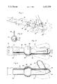
- FIG. 1 is a perspective view of the nozzle of the instant invention mounted on the inlet end of a suction dredging line;
- FIG. 2 is an end elevational view of the nozzle
- FIG. 3 is an enlarged top plan view of the nozzle with alternate positions of the inlet section thereof being illustrated in phantom lines;
- FIG. 4 is a vertical sectional view taken substantially upon the plane indicated by the section line 4--4 of FIG. 3.
- the numeral 10 generally designates a suction dredging line 10 including an inlet end 12.
- the suction nozzle assembly of the instant invention is referred to in general by the reference numeral 14 and includes an inlet end section 16 and an outlet end section 18.
- the outlet end section 18 includes an inlet end 20 and outlet end 22 while the inlet end section 16 includes an inlet end 24 and an outlet end 26.
- the outlet end 22 of the outlet end section 18 is substantially cylindrical and is snugly telescoped within the inlet end 12 of the suction line 10 and secured in position therein by a suitable hose clamp 28.
- the inlet end of the outlet end section defines a partial spherical bell end including a base section 30 formed integrally with the outlet end section 22 and a band section 32 which may be joined to the base section 30 by thermo welding or sonic welding after the inlet and outlet ends 20 and 26 have been coupled together.
- the inlet end 26 comprises a partial spherical bulbous end and may be universally received within the base end section 30 prior to the securement of the band section 32 to the base section 30. After the outlet end 26 has been seated in the base section 30, the band section 32 may be secured in position. In this manner, the inlet end section 16 will be supported from the outlet end section 18 for limited universal angular displacement relative thereto. In addition, the inlet end section 16 is supported from the outlet end section 18 for relative angular displacement about the longitudinal axis of the inlet section 16.
- the inlet end section 16 includes a U-shaped handle 34 which opens toward and has its free ends secured to the inlet end 24 of the inlet end section 16 with the handle 34 disposed in a rearwardly and upwardly inclined position relative to the inlet end section 16.
- the inlet end 24 is of a shape to define a forwardly and downwardly inclined inlet opening 36 which is of slightly smaller inside cross-sectional diameter than the inside cross-sectional diameter of the remainder of the inlet end section 16.
- the nozzle assembly 14 may be supported by the handle 34 and readily positioned as desired to effect an efficient suction dredging operation.
Landscapes
- Engineering & Computer Science (AREA)
- General Engineering & Computer Science (AREA)
- Mechanical Engineering (AREA)
- Mining & Mineral Resources (AREA)
- Civil Engineering (AREA)
- Structural Engineering (AREA)
- Jet Pumps And Other Pumps (AREA)
Abstract
Description
Claims (1)
Priority Applications (1)
| Application Number | Priority Date | Filing Date | Title |
|---|---|---|---|
| US06/398,583 US4423559A (en) | 1982-07-15 | 1982-07-15 | Gold dredge suction nozzle |
Applications Claiming Priority (1)
| Application Number | Priority Date | Filing Date | Title |
|---|---|---|---|
| US06/398,583 US4423559A (en) | 1982-07-15 | 1982-07-15 | Gold dredge suction nozzle |
Publications (1)
| Publication Number | Publication Date |
|---|---|
| US4423559A true US4423559A (en) | 1984-01-03 |
Family
ID=23575933
Family Applications (1)
| Application Number | Title | Priority Date | Filing Date |
|---|---|---|---|
| US06/398,583 Expired - Fee Related US4423559A (en) | 1982-07-15 | 1982-07-15 | Gold dredge suction nozzle |
Country Status (1)
| Country | Link |
|---|---|
| US (1) | US4423559A (en) |
Cited By (11)
| Publication number | Priority date | Publication date | Assignee | Title |
|---|---|---|---|---|
| US4622766A (en) * | 1985-06-03 | 1986-11-18 | Hall Gary R | Hand held suction nozzle with metal detector |
| US20030167595A1 (en) * | 2002-03-05 | 2003-09-11 | Samsung Gwangju Electronics Co., Ltd. | Joint assembly of vacuum cleaner and vacuum cleaner having the same |
| US20050120511A1 (en) * | 2002-01-07 | 2005-06-09 | Snatchers Company A/S | Removal of undesired occurrences in hair and fur |
| US20060191098A1 (en) * | 2005-02-28 | 2006-08-31 | Hiebert David B | Suction nozzle |
| US20090100724A1 (en) * | 2007-10-18 | 2009-04-23 | Oceaneering International, Inc. | Underwater Sediment Evacuation System |
| US20130340298A1 (en) * | 2012-06-20 | 2013-12-26 | Richard John Phillips | Dredging Head Apparatus |
| US20160194851A1 (en) * | 2012-12-20 | 2016-07-07 | Ihc Systems B.V. | Dredging arrangement for dredging material from an underwater bottom |
| US20180280127A1 (en) * | 2015-10-28 | 2018-10-04 | Stoma Ventures, LLC | Disposable dental valve device having a socket end |
| US10156057B2 (en) * | 2016-10-03 | 2018-12-18 | Vac-Tron Equipment, Llc | Rotatable hydro excavation suction wand |
| US11285512B2 (en) | 2020-07-30 | 2022-03-29 | Allen Robert Barnett | System, method and apparatus for a vacuum driven gold sifter |
| US11674286B2 (en) * | 2016-08-12 | 2023-06-13 | J.F. Brennan Company, Inc. | Dredge head assembly and related diver-assisted dredging system and methods |
-
1982
- 1982-07-15 US US06/398,583 patent/US4423559A/en not_active Expired - Fee Related
Cited By (15)
| Publication number | Priority date | Publication date | Assignee | Title |
|---|---|---|---|---|
| US4622766A (en) * | 1985-06-03 | 1986-11-18 | Hall Gary R | Hand held suction nozzle with metal detector |
| US20050120511A1 (en) * | 2002-01-07 | 2005-06-09 | Snatchers Company A/S | Removal of undesired occurrences in hair and fur |
| US20030167595A1 (en) * | 2002-03-05 | 2003-09-11 | Samsung Gwangju Electronics Co., Ltd. | Joint assembly of vacuum cleaner and vacuum cleaner having the same |
| US6904640B2 (en) * | 2002-03-05 | 2005-06-14 | Samsung Gwangju Electronics Co. | Joint assembly of vacuum cleaner and vacuum cleaner having the same |
| US20060191098A1 (en) * | 2005-02-28 | 2006-08-31 | Hiebert David B | Suction nozzle |
| US7621059B2 (en) * | 2007-10-18 | 2009-11-24 | Oceaneering International, Inc. | Underwater sediment evacuation system |
| US20090100724A1 (en) * | 2007-10-18 | 2009-04-23 | Oceaneering International, Inc. | Underwater Sediment Evacuation System |
| US20130340298A1 (en) * | 2012-06-20 | 2013-12-26 | Richard John Phillips | Dredging Head Apparatus |
| US9200427B2 (en) * | 2012-06-20 | 2015-12-01 | Richard John Phillips | Dredging head apparatus |
| US20160194851A1 (en) * | 2012-12-20 | 2016-07-07 | Ihc Systems B.V. | Dredging arrangement for dredging material from an underwater bottom |
| US20180280127A1 (en) * | 2015-10-28 | 2018-10-04 | Stoma Ventures, LLC | Disposable dental valve device having a socket end |
| US10925701B2 (en) * | 2015-10-28 | 2021-02-23 | Stoma Ventures, LLC | Disposable dental valve device having a socket end |
| US11674286B2 (en) * | 2016-08-12 | 2023-06-13 | J.F. Brennan Company, Inc. | Dredge head assembly and related diver-assisted dredging system and methods |
| US10156057B2 (en) * | 2016-10-03 | 2018-12-18 | Vac-Tron Equipment, Llc | Rotatable hydro excavation suction wand |
| US11285512B2 (en) | 2020-07-30 | 2022-03-29 | Allen Robert Barnett | System, method and apparatus for a vacuum driven gold sifter |
Similar Documents
| Publication | Publication Date | Title |
|---|---|---|
| US4423559A (en) | Gold dredge suction nozzle | |
| US4091998A (en) | Retainer clamp | |
| US3908910A (en) | Cleaning tool for gutters and eavetroughs | |
| US4132507A (en) | Blowing apparatus | |
| US5768749A (en) | Portable air blower | |
| US4269571A (en) | Blowing apparatus | |
| US6055703A (en) | Upright vacuum cleaner having improved steering apparatus with a lock out feature | |
| KR100750710B1 (en) | Wand assembly for a vacuum cleaner | |
| US5447349A (en) | Auxiliary handle for shovels | |
| US3707737A (en) | Apparatus for cleaning submerged surfaces | |
| US1964263A (en) | Spraying fixture | |
| JPS6187040A (en) | Monitor | |
| RU2007138279A (en) | SURFACE TREATMENT DEVICE | |
| US4899940A (en) | Spray washing device for motor vehicles and the like | |
| JPH108430A (en) | Blower pipe | |
| US7287926B2 (en) | Fluid squeegee | |
| US6119738A (en) | Inflating device | |
| CA1201455A (en) | Gold dredge suction nozzle | |
| NZ195209A (en) | Teat cup inflation with annular flexible zone | |
| GB1567326A (en) | Connector arrangement for connecting a wc pan outlet to a soil pipe | |
| US3473738A (en) | Hose control device | |
| US2738615A (en) | Hand operated insect duster | |
| US4396155A (en) | Shower head | |
| CN217601891U (en) | Groove cleaning device | |
| GB2138704A (en) | Impact Drive Sprinkler |
Legal Events
| Date | Code | Title | Description |
|---|---|---|---|
| MAFP | Maintenance fee payment |
Free format text: PAYMENT OF MAINTENANCE FEE, 4TH YEAR, PL 96-517 (ORIGINAL EVENT CODE: M170); ENTITY STATUS OF PATENT OWNER: SMALL ENTITY Year of fee payment: 4 |
|
| FEPP | Fee payment procedure |
Free format text: PAYOR NUMBER ASSIGNED (ORIGINAL EVENT CODE: ASPN); ENTITY STATUS OF PATENT OWNER: SMALL ENTITY |
|
| FEPP | Fee payment procedure |
Free format text: PAYER NUMBER DE-ASSIGNED (ORIGINAL EVENT CODE: RMPN); ENTITY STATUS OF PATENT OWNER: SMALL ENTITY |
|
| FEPP | Fee payment procedure |
Free format text: PAYOR NUMBER ASSIGNED (ORIGINAL EVENT CODE: ASPN); ENTITY STATUS OF PATENT OWNER: SMALL ENTITY |
|
| FEPP | Fee payment procedure |
Free format text: MAINTENANCE FEE REMINDER MAILED (ORIGINAL EVENT CODE: REM.); ENTITY STATUS OF PATENT OWNER: SMALL ENTITY |
|
| LAPS | Lapse for failure to pay maintenance fees | ||
| FP | Lapsed due to failure to pay maintenance fee |
Effective date: 19911229 |
|
| STCH | Information on status: patent discontinuation |
Free format text: PATENT EXPIRED DUE TO NONPAYMENT OF MAINTENANCE FEES UNDER 37 CFR 1.362 |