US4422571A - Proportional motor drive control - Google Patents
Proportional motor drive control Download PDFInfo
- Publication number
- US4422571A US4422571A US06/266,461 US26646181A US4422571A US 4422571 A US4422571 A US 4422571A US 26646181 A US26646181 A US 26646181A US 4422571 A US4422571 A US 4422571A
- Authority
- US
- United States
- Prior art keywords
- signal
- temperature
- velocity
- scaled
- air
- Prior art date
- Legal status (The legal status is an assumption and is not a legal conclusion. Google has not performed a legal analysis and makes no representation as to the accuracy of the status listed.)
- Expired - Fee Related
Links
Images

Classifications
-
- G—PHYSICS
- G05—CONTROLLING; REGULATING
- G05D—SYSTEMS FOR CONTROLLING OR REGULATING NON-ELECTRIC VARIABLES
- G05D23/00—Control of temperature
- G05D23/19—Control of temperature characterised by the use of electric means
- G05D23/20—Control of temperature characterised by the use of electric means with sensing elements having variation of electric or magnetic properties with change of temperature
-
- F—MECHANICAL ENGINEERING; LIGHTING; HEATING; WEAPONS; BLASTING
- F24—HEATING; RANGES; VENTILATING
- F24F—AIR-CONDITIONING; AIR-HUMIDIFICATION; VENTILATION; USE OF AIR CURRENTS FOR SCREENING
- F24F11/00—Control or safety arrangements
- F24F11/70—Control systems characterised by their outputs; Constructional details thereof
- F24F11/72—Control systems characterised by their outputs; Constructional details thereof for controlling the supply of treated air, e.g. its pressure
- F24F11/74—Control systems characterised by their outputs; Constructional details thereof for controlling the supply of treated air, e.g. its pressure for controlling air flow rate or air velocity
- F24F11/76—Control systems characterised by their outputs; Constructional details thereof for controlling the supply of treated air, e.g. its pressure for controlling air flow rate or air velocity by means responsive to temperature, e.g. bimetal springs
-
- F—MECHANICAL ENGINEERING; LIGHTING; HEATING; WEAPONS; BLASTING
- F24—HEATING; RANGES; VENTILATING
- F24F—AIR-CONDITIONING; AIR-HUMIDIFICATION; VENTILATION; USE OF AIR CURRENTS FOR SCREENING
- F24F11/00—Control or safety arrangements
- F24F11/88—Electrical aspects, e.g. circuits
-
- G—PHYSICS
- G05—CONTROLLING; REGULATING
- G05D—SYSTEMS FOR CONTROLLING OR REGULATING NON-ELECTRIC VARIABLES
- G05D23/00—Control of temperature
- G05D23/19—Control of temperature characterised by the use of electric means
- G05D23/1906—Control of temperature characterised by the use of electric means using an analogue comparing device
-
- F—MECHANICAL ENGINEERING; LIGHTING; HEATING; WEAPONS; BLASTING
- F24—HEATING; RANGES; VENTILATING
- F24F—AIR-CONDITIONING; AIR-HUMIDIFICATION; VENTILATION; USE OF AIR CURRENTS FOR SCREENING
- F24F11/00—Control or safety arrangements
- F24F11/30—Control or safety arrangements for purposes related to the operation of the system, e.g. for safety or monitoring
-
- F—MECHANICAL ENGINEERING; LIGHTING; HEATING; WEAPONS; BLASTING
- F24—HEATING; RANGES; VENTILATING
- F24F—AIR-CONDITIONING; AIR-HUMIDIFICATION; VENTILATION; USE OF AIR CURRENTS FOR SCREENING
- F24F11/00—Control or safety arrangements
- F24F11/70—Control systems characterised by their outputs; Constructional details thereof
- F24F11/72—Control systems characterised by their outputs; Constructional details thereof for controlling the supply of treated air, e.g. its pressure
- F24F11/74—Control systems characterised by their outputs; Constructional details thereof for controlling the supply of treated air, e.g. its pressure for controlling air flow rate or air velocity
-
- F—MECHANICAL ENGINEERING; LIGHTING; HEATING; WEAPONS; BLASTING
- F24—HEATING; RANGES; VENTILATING
- F24F—AIR-CONDITIONING; AIR-HUMIDIFICATION; VENTILATION; USE OF AIR CURRENTS FOR SCREENING
- F24F2110/00—Control inputs relating to air properties
- F24F2110/10—Temperature
Definitions
- the present invention relates generally to air conditioning control systems and more specifically to a system for controlling the position of air conditioning dampers as a function of two sensed parameters.
- Variable volume air conditioning systems provide for heating and cooling rooms, or zones of rooms, by adjusting the rate of flow into each room or zone.
- the temperature of the incoming air remains constant, with only the rate at which air moves into the zone being variable.
- a number of devices for positioning dampers in ducts to control air flow have been developed.
- the movable dampers are opened or closed to adjust the volume of air flowing into the zone.
- the speed of the motor driving the dampers can be made variable to improve the response time of the system.
- the accuracy of conventional systems is limited due to the substantial feed back delay between operation of the dampers and a change in room temperature. This causes the dampers to be overdriven. For example, if the room becomes too hot the dampers are opened to increase air flow and lower the temperature. When the room reaches the desired temperature, the dampers are closed back to their normal position. However, the temperature of the room will continue to fall for a short period of time. This causes the dampers to close further to warm the room. Usually, the room temperature will overshoot the desired setting several times before settling down. Such excursions of room temperature often define a damped oscillation.
- a characteristic of present systems is that the room temperature variable gives rise to a certain damper position.
- various static pressures and flow rates in the system of a building cause the damper position to inaccurately indicate the volume of air flowing into the zone. That is, for a given damper position, the volume of air flowing into the zone can fluctuate over a wide range.
- variable volume control systems are characterized by limited accuracy and slow response time to bring the room back to the preselected temperature because the input signal consists of only one variable, that being the temperature of the room. The effect of having the only system feedback parameter increases these inaccuracies.
- a variable volume air conditioning system controls the temperature of a room, or of a zone composed of several rooms, by controlling the rate of flow of cooled or heated air flowing into the zone.
- the temperature of the air supplied by a central source to be used in a plurality of zones remains constant.
- Each zone has a control system to control the volume of air flowing into that zone.
- the volume of air flowing into a particular zone is controlled by the use of variable position dampers.
- the position of the dampers can vary between fully closed, which prevents entry of conditioned air into the zone, and fully open, which causes air to flow into the zone at a maximum rate determined by the central blower fan.
- variable volume air conditioning system is suitable for both cooling and heating. Control of the volume of air entering a zone is conditioned upon the relationship between the air temperature in that zone and the volume of air moving into it.
- a high zone temperature causes the air flow to be increased, and a low zone temperature decreases the air flow.
- Whe used in the heating mode a high temperature in the zone causes the air flow to be decreased, and a low zone temperature increases the air flow.
- the preferred embodiment of the present invention provides that a polarity change in a voltage signal from a zone thermostat causes the system to switch between the cooling and heating modes.
- the air flow into each room or zone is controlled by a set of adjustable dampers driven by a damper motor.
- An air velocity sensor provides an input proportional to the volume of air flowing into the zone to a control circuit.
- a temperature sensor provides a second input to the control circuit.
- the temperature and velocity signals are scaled and compared directly.
- the signal having the largest magnitude determines the direction in which the damper motor is driven.
- Control means are provided for driving the damper motor at a rate proportional to the difference in magnitude between the scaled temperature and velocity signals.
- FIG. 1 is a block diagram of a variable volume air conditioning system
- FIG. 2 is a block diagram of a control circuit for the air conditioning system of FIG. 1;
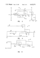
- FIG. 3 is a schematic diagram of an amplifying circuit for a temperature signal
- FIG. 4 is a schematic diagram for a velocity scaling circuit
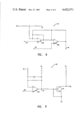
- FIG. 5 is a schematic diagram for a velocity minus temperature subtractor
- FIG. 6 is a schematic diagram for a temperature minus velocity subtractor
- FIG. 7 is a schematic diagram of a positive mode switch.
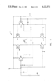
- FIG. 8 is a schematic diagram of a damper motor drive control circuit.
- a year round air conditioning system is designated generally by the reference numeral 10.
- the system is shown supplying air to only two zones 12 and 14, but this number may be made as large as desired. Each zone is independently controlled.
- a controlled temperature air supply 16 and a blower 18 represent the main air supply system. Air is supplied from the temperature control 16 at a constant temperature, being cold in the summer and hot during the winter. The blower 18 forces air through the system. The air is passed through one or a series of distribution ducts 20, and finally through one zone distribution duct 22, 22a, respectively, for each zone 12, 14.
- FIG. 1 shows one air outlet 24, 24a into each zone 12, 14, respectively, for discussion purposes.
- each zone 12, 14 will typically have at least two entry points for the conditioned air.
- variable volume system The following discussion of the apparatus and operation of the variable volume system will be directed to the first zone 12. However, it is understood that the apparatus of the second zone 14 operates identically and devices located in the second zone will be referenced by the same numerals as their counterparts in the first zone 12, with the suffix "a" following the numeral.
- a set of dampers 26 is located in the zone distribution duct 22 prior to the point where it divides to distribute air to the various parts of the zone 12. These dampers are rotated by the action of a damper motor 28. As shown in FIG. 1, when the dampers 26 are rotated clockwise, they restrict the flow of conditioned air into the zone 12. Rotating the dampers 26 counterclockwise opens the cross-section of the duct 22 and allows a greater volume of air to enter the zone 12. By controlling the position of the dampers 26, the volume of air flow into the zone 12 can be accurately controlled.
- the embodiment of FIG. 1 includes baffles 30 located downstream of the dampers 26 to minimize noise.
- a velocity sensor 32 is provided in the zone distribution duct 22 to monitor the volume of air flow.
- the air temperature in the zone is detected by a thermostat 34.
- the thermostat 34 provides a voltage 36 proportional to the zone 12 temperature.
- the thermostat voltage 36 decreases with increasing temperature.
- the control system 10 is operating in the cooling mode.
- it is merely necessary to reverse the polarity of the thermostat voltage 36 which is preferably accomplished by a switch located on the thermostat 34.
- the control system 10 will be operating in the heating mode.
- operation of the system 10 is discussed with reference to the cooling mode. System operation in the heating mode will generally become apparent from the following explanation, and specific differences will be indicated.
- the control circuit 40 controls the operation of the damper motor 28.
- the damper motor 28 is a bi-directional, variable speed DC motor. This allows the control circuit 40 to control both the direction and speed of operation of the motor 28. In this embodiment, slight changes in room 12 temperature can be compensated for by slowly moving the damper motor 28. As the proper temperature is reached, the speed of the damper motor 28 decreases. This allows the dampers 26 to reach the correct position without overshooting, and thus, avoids oscillation in the position of the dampers 26.
- the control circuit 40 drives an AC motor, in which case the control circuit 40 would merely determine the direction of operation of the damper motor 28.
- the damper motor 28 When the actual room temperature is equal to the desired room temperature, the damper motor 28 is not in operation. If the zone 12 becomes too hot, there is a decrease in the temperature signal voltage 36, which causes the control circuit 40 to open the dampers 26. This causes an increase in volume of cool air flowing into the room 12, which lowers the room temperature. If the temperature in the room 12 becomes too low, the control circuit 40 causes the damper motor 28 to drive the dampers 26 toward the closed position. This decreases the volume of air flowing into the zone 12, which results in a rise in the zone temperature.
- the damper motor 28 preferably drives the dampers 26 from the fully opened to the fully closed position in a matter of minutes rather than seconds.
- the air temperature in the zone 12 does not change quickly when the dampers 26 are open or shut.
- the control circuit 40 directly compares voltage signals 36, 38 from the velocity sensor 32 and the thermostat 34. This provides greatly increased accuracy and decreased response time as opposed to employing merely a thermostat 34 to provide the signal for driving a damper motor 28.
- the present control circuit 40 directly compares the velocity and temperature signals 36, 38 so that the dampers 26 are positioned to cause one correct velocity flow for a given room temperature. As the room temperature changes, the velocity flow, as controlled by the damper 26 position, will change with it. The actual air velocity is detected in the preferred embodiment, rather than merely approximating the velocity by detecting the position of the dampers 26.
- One aspect of the preferred embodiment provides for driving the damper motor 28, and thus the dampers 26, at a rate proportional to the magnitude of the difference between the temperature signal 36 and the velocity signal 38. This is possible when a DC motor 28 is used to drive the dampers 26.
- One aspect of the preferred embodiment provides for driving the damper motor 28, and thus the dampers 26, at a rate proportional to the magnitude of the difference between the temperature signal 36 and the velocity signal 38.
- the damper motor 28 When the difference between the control signals 36, 38 is large, the damper motor 28 is driven at a relatively high speed. When the difference is small, the damper motor 28 is driven at a relatively low speed. If the signals 36, 38 have the same value, the motor 28 is not operated.
- the control circuit 40 applies a drive signal 42 to the motor 28 to open the dampers 26 to begin to open.
- the difference between the temperature signal 36 and the velocity signal 38 decreases. This causes the damper motor 28 to be driven at a slower rate.
- the velocity signal 38 will increase to a point where there is no difference between the temperature signal 36 and the velocity signal 38, and the dampers 26 will cease to move.
- the temperature signal 36 will drop back to its desired level.
- the control circuit 40 will register an air velocity that is too large, and begin closing the dampers 26.
- the dampers 26 are slowly closed. Therefore, when the room 12 reaches the equlibrium level, the dampers 26 will already be in the correct position.
- the velocity signal 38 is coupled to a velocity scaling circuit 44.
- the output 46 of the scaling circuit 44 has the opposite sign as the velocity signal 38, so that an increase in the air velocity causes a decrease in the velocity scaling circuit output 46.
- the velocity scaling circuit 44 also has an adjustable gain so that the scaled velocity signal 46 can be calibrated to the rest of the system.
- the temperature signal 36 is coupled to a temperature scaling circuit 48, the output 50 of which has the same sign as that of the input. This is because the temperature signal 36 changes in the opposite direction relative to changes in the zone 12 temperature.
- the scaled velocity signal 46 and scaled temperature signal 50 are each coupled to an input to a first subtractor 52 and a second subtractor 54. In the first subtractor 52, the scaled temperature signal 50 is subtracted from the scaled velocity signal 46. In the second subtractor 54, the scaled velocity signal 46 is subtracted from the scaled temperature signal 50. It will be apparent that a first subtractor output 56 and a second subtractor output 58 will have the same magnitude and opposite signs.
- the first and second subtractor outputs 56, 58 are coupled to a positive mode switch 60. The switch 60 selects the subtractor signal 56, 58 having a positive sign.
- the output from the positive mode switch 60 is coupled to a motor drive control 62.
- the drive control 62 selects the information transmitted by the switch 60, and drives the damper motor 28 in a direction determined by the selected signal 56, 58.
- the speed of the motor 28 is determined by the magnitude of the difference between the scaled velocity signal 46 and the scaled temperature signal 50.
- the motor 28 When the scaled velocity and temperature signals 46, 50 are equal, the motor 28 will remain off. If the scaled velocity signal 46 decreases below the scaled temperature signal 50, indicating that the air flow into the zone 12 is too high for the present zone temperature, the drive control 62 will drive the motor 28 to close the dampers 26. If the scaled temperature signal 50 is lower than the scaled velocity signal 46, indicating that the temperature in the zone 12 is too high, the drive control 62 will operate the damper motor 28 to open the dampers 26 until the scaled velocity and temperature signals 46 and 50 become equal.
- FIGS. 3 through 8 utilize a common power supply (not shown).
- the supply used is preferably a 12 volt regulated supply.
- the 12 volt power supply voltage is referenced as Vo in all FIGURES.
- FIG. 3 A preferred embodiment for the temperature scaling circuit 48 is shown in FIG. 3.
- the temperature signal 36 of the theromstat 34 is connected to the positive input of an operational amplifier (OP AMP) OA1.
- OP AMP operational amplifier
- First and second variable resistors R1 and R2 provide for calibration of the circuit, and are connected to the negative input of OA1.
- the circuit shown in FIG. 3 includes a third variable resistor R3 for controlling the minimum damper open position and a fourth variable resistor R4 for controlling the maximum damper open position.
- These resistors R3, R4 are preferably adjustable by the system user, and allow the user to prevent the dampers 26 from reaching the fully closed or fully opened positions.
- Diodes D1, D2 and D3 control the flow of current in the temperature scaling circuit 48.
- Voltage V1 at the cathode of diode D3 varies directly with the thermostat input voltage 36. Therefore, V1 decreases with increasing temperature when the system 10 is in the cooling mode.
- Voltage V2 between the anodes of D1 and D2 varies with the thermostat voltage 36.
- the fixed voltage drop across D1 causes the output of OA1 and V2 to differ by the fixed forward bias voltage whenever the output of OA1 is less than a pick-off voltage V3. If the output of OA1 rises above V3, D1 becomes reverse biased, and V2 is equal to V3 minus the small voltage drop across pick-off resistor R5. V1 differs from V2 by the fixed drops across D2 and D3.
- V1 rises and falls with the thermostat signal 36, but V1 will not rise above a value determined by the setting of variable resistor R3. Since a higher thermostat voltage 36 indicates a lower temperature, the variable resistor R3 sets the lowest temperature which the next stage of the control circuit 40 will read. Since a minimum velocity corresponds to a minimum temperature, adjustment of R3 sets the limit to which the dampers 26 will close. Adjusting R3 so that the pick-off voltage V3 is equal to the source voltage Vo allows the dampers 26 to be fully closed.
- variable resistor R4 operates to establish the maximum open damper 26 position. Setting variable resistor R4 establishes the minimum scaled temperature output voltage 50. Therefore, even though the temperature voltage signal 36 from the thermostat decreases, indicating increasing temperature, the scaled temperature output 50 will not decrease past a certain value, and will be read by the control circuit 40 as a constant temperature.
- V1 will be that set by R4 unless V2 is greater than that value by at least the fixed voltage drops across D2 and D3. When V2 is high enough, V1 will track the variations due to a changing thermostat voltage 36.
- V1 varies with the thermostat signal 36 between selected maximum ranges.
- the scaled temperature signal 50 is a fixed fraction of V1 determined by the voltage divider made up of resistors R6 and R7.
- the control circuit 40 establishes the velocity through the air conditioning duct 22 as a function of the room temperature.
- maximum and minimum limits on the scaled temperature signal 50 maximum and minimum limits on flow velocity are thereby automatically set. It will be apparent that it would be possible to set the limits by controlling the maximum and minimum scaled velocity voltages 46. Other methods of setting the maximum and minimum damper 26 positions may become apparent to those skilled in the art.
- the velocity signal 38 is coupled to the negative input of an OP AMP OA2 through a resistive voltage divider network which includes variable resistor R8.
- the velocity signal 38 is added to a constant voltage defined by two resistors R10 and R11 before coupling to the negative input OA2.
- a voltage input to the positive input of the OP AMP OA2 can be calibrated through the use of a variable resistor R12.
- the scaled velocity output voltage 46 decreases with increasing air velocity.
- the adjustable inputs to the OP AMP OA2 set the gain and DC offset so that the scaled velocity voltage 46 varies over the same range as the scaled temperature voltage 50. Therefore, these values can now be directly compared.
- FIG. 5 shows a preferred embodiment for a velocity minus temperature subtractor circuit 52.
- the scaled velocity voltage 46 is coupled to the positive input of an OP AMP OA3.
- the scaled temperature voltage 50 is coupled to the negative input of OP AMP OA3 through an OP AMP OA4.
- Resistor values are chosen so that the gain of each OP AMP OA3 and OA4 is one, so that the scaled velocity 46 and temperature 50 voltages are directly compared.
- the overall gain of 52 is greater than unity.
- the second subtractor 54 is identical to the circuitry of the first subtractor 52 except that the velocity and temperature inputs 46 and 50 have been interchanged. That is, the scaled temperature input 50 is coupled to the positive input of an OP AMP OA5, with the scaled velocity input 46 coupled to the negative input of the OP AMP OA5 through an OP AMP OA6.
- the resistors are chosen as those in the first subtractor 52 so that the second subtractor output 58 is equal to the difference in magnitudes of the scaled temperature 50 and velocity 46 signal times the overall circuit gain.
- first and second subtractor outputs 56 and 58 will have the same magnitude by interchanging inputs.
- the magnitude of each of the subtractor outputs 56, 58 indicates whether the input air velocity should be increased or decreased, the magnitude of the difference indicates the magnitude of this change needed.
- the magnitudes of the first and second subtractor outputs 56, 58 are equal, the air velocity into the zone 12 is correct for the present zone temperature.
- a preferred embodiment of a positive mode switch 60 is shown.
- the first subtractor output 56 is connected directly to the negative input of an operational amplifier OA7.
- the second subtractor output 58 is coupled to the positive input of OA7. If the scaled velocity signal 46 is greater than the scaled temperature signal 50, the voltage 56 at the negative input to the OP AMP OA7 will be more positive, then voltage 58 at the positive input. Therefore, the OP AMP OA7 output voltage V4 will be low. This low voltage will not provide the necessary voltage at the base of a switch transistor Q1 to turn it on, so that the transistor Q1 collector voltage V5 will increase toward the power supply voltage V0. If the velocity signal 46 is greater than the temperature signal 48, a first switch output V6 connected to the OP AMP output V4 will be low, and the switch transistor collector voltage V5 will be high.
- V4 will be high, thereby turning on the output transistor Q1.
- the collector voltage V5 will be low.
- V6 follows V4 and assures positive polarity switching to the motor.
- V5 is always out of phase with V6 and also assures proper polarity switching to the motor.
- the first switch output V6 is connected to the base of a first drive transistor Q2 and the collector output V5 is coupled to the base of a second drive transistor Q3. Since V6 and V5 outputs always have opposite polarity in voltage, one of the drive transistors Q2 or Q3 will be on while the other is off.
- the first subtractor output 56 is coupled to the base of a third transistor Q4, the collector of which is coupled to the base of a fourth drive transistor Q5.
- the second subtractor output 58 is coupled to the base of a fifth drive transistor Q6, the collector of which is coupled to the base of a sixth drive transistor Q7.
- the drive transistor Q3 When the first subtractor output voltage 56 is positive, the drive transistor Q3 will be turned on by the positive mode switch 60. Transistor Q4 will be turned on by the positive first subtractor signal 56, which lowers the voltage at the collector to transistor Q4. This causes transistor Q5 to turn on, thereby conducting current. Transistors Q4 and Q5 do not switch between on and off logical states, but rather conduct current in proportion to the magnitude of the signal received from the first subtractor output 56. Therefore, the current through transistor Q5 varies with the magnitude of the difference between the scaled velocity 46 and temperature 50 signals.
- transistors Q2, Q6 and Q7 are nonconducting.
- Transistor Q3 conducts in an on state, and transistors Q4 and Q5 conduct a current proportional to the magnitude difference between the scaled temperature 46 and velocity 50 signals.
- Current conducted by the drive transistor Q5 passes through the variable speed DC motor 28 and to circuit ground through transistor Q3. It will be apparent that when the scaled temperature and velocity voltage 46, 50 magnitudes are substantially equal, one of the differential pair of transistors Q2 or Q3 will still be turned on due to the action of the positive mode switch 60. However, no current is conducted through the electric motor 28, as there will not be a large enough voltage to turn on either transistors Q4 or Q6 and allow current to be conducted through the motor 28.
- the symmetrical motor drive circuit 62 works as described above by having transistors Q2, Q6 and Q7 conducting while transistors Q3, Q4 and Q5 are nonconducting. Again, the rate of current flow through the electric motor 28 varies with the difference in magnitude between the scaled temperature and velocity signals 46, 50.
- the thermostat 34 can be any thermostat that generates a varying voltage with temperature variations.
- the preferred embodiment utilizes a thermostat 34 which generates a decreasing voltage with increasing room temperature.
- Any velocity sensor 32 which generates a voltage proportional to air flow may be used.
- the velocity sensor voltage 38 increase with increasing air flow.
- An example of a preferred velocity sensor is shown in a copending U.S. application by the same inventor, entitled AIR FLOW SENSOR, Ser. No. 266,487, filed on May 22, 1981.
Landscapes
- Engineering & Computer Science (AREA)
- Physics & Mathematics (AREA)
- General Physics & Mathematics (AREA)
- Automation & Control Theory (AREA)
- Chemical & Material Sciences (AREA)
- Combustion & Propulsion (AREA)
- Mechanical Engineering (AREA)
- General Engineering & Computer Science (AREA)
- Fluid Mechanics (AREA)
- Air Conditioning Control Device (AREA)
Abstract
Description
Claims (7)
Priority Applications (2)
| Application Number | Priority Date | Filing Date | Title |
|---|---|---|---|
| US06/266,461 US4422571A (en) | 1981-05-22 | 1981-05-22 | Proportional motor drive control |
| US06/502,555 US4607789A (en) | 1981-05-22 | 1983-06-09 | Proportional motor drive control |
Applications Claiming Priority (1)
| Application Number | Priority Date | Filing Date | Title |
|---|---|---|---|
| US06/266,461 US4422571A (en) | 1981-05-22 | 1981-05-22 | Proportional motor drive control |
Related Child Applications (1)
| Application Number | Title | Priority Date | Filing Date |
|---|---|---|---|
| US06/502,555 Division US4607789A (en) | 1981-05-22 | 1983-06-09 | Proportional motor drive control |
Publications (1)
| Publication Number | Publication Date |
|---|---|
| US4422571A true US4422571A (en) | 1983-12-27 |
Family
ID=23014682
Family Applications (1)
| Application Number | Title | Priority Date | Filing Date |
|---|---|---|---|
| US06/266,461 Expired - Fee Related US4422571A (en) | 1981-05-22 | 1981-05-22 | Proportional motor drive control |
Country Status (1)
| Country | Link |
|---|---|
| US (1) | US4422571A (en) |
Cited By (12)
| Publication number | Priority date | Publication date | Assignee | Title |
|---|---|---|---|---|
| US4487254A (en) * | 1982-04-16 | 1984-12-11 | Hitachi, Ltd. | Temperature control unit for vehicular air conditioning unit |
| US4607789A (en) * | 1981-05-22 | 1986-08-26 | Hoffman Controls Corporation | Proportional motor drive control |
| US4732318A (en) * | 1986-01-17 | 1988-03-22 | Osheroff Gene W | Velocity controlled forced air temperature control system |
| US4817865A (en) * | 1988-03-17 | 1989-04-04 | Racal Data Communications Inc. | Ventilation system for modular electronic housing |
| US4838484A (en) * | 1987-07-31 | 1989-06-13 | Kreuter Manufacturing Co., Inc. | Variable volume air conditioning system with velocity readout at the thermostat |
| US4917174A (en) * | 1988-07-25 | 1990-04-17 | American Standard Inc. | Supply airflow control for dual-duct system |
| US4957238A (en) * | 1989-10-30 | 1990-09-18 | Kreuter Mfg. Co., Inc. | Pneumatic variable air volume controller |
| US5209073A (en) * | 1990-11-01 | 1993-05-11 | Fisher & Paykel Limited | Cooling device and method with multiple cooled chambers and multiple expansion means |
| US20040209566A1 (en) * | 2003-04-17 | 2004-10-21 | Guy Caliendo | Multi-mode damper actuator |
| EP1530008A1 (en) * | 2002-08-12 | 2005-05-11 | Daikin Industries, Ltd. | Air conditioner and method of controlling air conditioner |
| US20050278071A1 (en) * | 2004-06-14 | 2005-12-15 | Durham Ormonde G Iii | Adaptable HVAC; AC motor speed, air temperature and air quality control system |
| CN102980347A (en) * | 2012-12-03 | 2013-03-20 | 合肥美的荣事达电冰箱有限公司 | Electric air door driving device and refrigerator |
Citations (3)
| Publication number | Priority date | Publication date | Assignee | Title |
|---|---|---|---|---|
| US3941310A (en) * | 1974-01-28 | 1976-03-02 | Wehr Corporation | Thermostatic control for use in variable air distribution systems |
| US4042173A (en) * | 1975-09-04 | 1977-08-16 | Barber-Colman Company | Method and apparatus for controlling volume air flow |
| US4284237A (en) * | 1980-05-12 | 1981-08-18 | Anemostat Products Div., Dynamics Corporation Of America | Air conditioning control system with master and tracking controllers |
-
1981
- 1981-05-22 US US06/266,461 patent/US4422571A/en not_active Expired - Fee Related
Patent Citations (3)
| Publication number | Priority date | Publication date | Assignee | Title |
|---|---|---|---|---|
| US3941310A (en) * | 1974-01-28 | 1976-03-02 | Wehr Corporation | Thermostatic control for use in variable air distribution systems |
| US4042173A (en) * | 1975-09-04 | 1977-08-16 | Barber-Colman Company | Method and apparatus for controlling volume air flow |
| US4284237A (en) * | 1980-05-12 | 1981-08-18 | Anemostat Products Div., Dynamics Corporation Of America | Air conditioning control system with master and tracking controllers |
Cited By (18)
| Publication number | Priority date | Publication date | Assignee | Title |
|---|---|---|---|---|
| US4607789A (en) * | 1981-05-22 | 1986-08-26 | Hoffman Controls Corporation | Proportional motor drive control |
| US4487254A (en) * | 1982-04-16 | 1984-12-11 | Hitachi, Ltd. | Temperature control unit for vehicular air conditioning unit |
| US4732318A (en) * | 1986-01-17 | 1988-03-22 | Osheroff Gene W | Velocity controlled forced air temperature control system |
| US4838484A (en) * | 1987-07-31 | 1989-06-13 | Kreuter Manufacturing Co., Inc. | Variable volume air conditioning system with velocity readout at the thermostat |
| US4817865A (en) * | 1988-03-17 | 1989-04-04 | Racal Data Communications Inc. | Ventilation system for modular electronic housing |
| US4917174A (en) * | 1988-07-25 | 1990-04-17 | American Standard Inc. | Supply airflow control for dual-duct system |
| US4957238A (en) * | 1989-10-30 | 1990-09-18 | Kreuter Mfg. Co., Inc. | Pneumatic variable air volume controller |
| US5209073A (en) * | 1990-11-01 | 1993-05-11 | Fisher & Paykel Limited | Cooling device and method with multiple cooled chambers and multiple expansion means |
| EP1530008A4 (en) * | 2002-08-12 | 2008-04-02 | Daikin Ind Ltd | Air conditioner and method of controlling air conditioner |
| EP1530008A1 (en) * | 2002-08-12 | 2005-05-11 | Daikin Industries, Ltd. | Air conditioner and method of controlling air conditioner |
| US7033268B2 (en) * | 2003-04-17 | 2006-04-25 | Siemens Building Technologies, Inc. | Multi-mode damper actuator |
| US20040209566A1 (en) * | 2003-04-17 | 2004-10-21 | Guy Caliendo | Multi-mode damper actuator |
| US20050278071A1 (en) * | 2004-06-14 | 2005-12-15 | Durham Ormonde G Iii | Adaptable HVAC; AC motor speed, air temperature and air quality control system |
| US7797080B2 (en) | 2004-06-14 | 2010-09-14 | Ogd V-Hvac Inc. | Opto-programmed HVAC controller |
| US20100274395A1 (en) * | 2004-06-14 | 2010-10-28 | Ogd V-Hvac, Inc. | Adaptable hvac; ac motor speed, air temperature and air quality control system |
| US7899579B2 (en) | 2004-06-14 | 2011-03-01 | Ogd V-Hvac, Inc. | Adaptable HVAC; AC motor speed, air temperature and air quality control system |
| CN102980347A (en) * | 2012-12-03 | 2013-03-20 | 合肥美的荣事达电冰箱有限公司 | Electric air door driving device and refrigerator |
| CN102980347B (en) * | 2012-12-03 | 2015-02-25 | 合肥美的电冰箱有限公司 | Electric air door driving device and refrigerator |
Similar Documents
| Publication | Publication Date | Title |
|---|---|---|
| US4607789A (en) | Proportional motor drive control | |
| US4422571A (en) | Proportional motor drive control | |
| US4406397A (en) | Central air conditioning equipment | |
| US3933197A (en) | Control of heating and cooling available from central sources to a multi-zone temperature controlled space | |
| US3834617A (en) | Pid controller for heating, ventilating and air conditioning systems | |
| US5769314A (en) | Variable air volume HVAC system controller and method | |
| US3377545A (en) | Thermostatic transducer for winter and summer operation | |
| US7204429B2 (en) | Controller for forced-air HVAC system | |
| US4392417A (en) | Variable dead band pressure control system | |
| US4182484A (en) | Temperature control for variable volume air conditioning system | |
| US4244517A (en) | Temperature control for variable volume air conditioning system | |
| JPS5839083B2 (en) | Automotive air conditioner | |
| US3901310A (en) | Multizone environmental control system | |
| US3594546A (en) | Air temperature control apparatus | |
| US4585163A (en) | Variable air volume system control | |
| US5821741A (en) | Temperature set point circuit and method employing adjustment resistor | |
| US4070610A (en) | Proportional motor circuit | |
| US4917174A (en) | Supply airflow control for dual-duct system | |
| US3887127A (en) | Method of and control circuit for admixing air | |
| US2828464A (en) | Control of air-conditioning apparatus | |
| US4838484A (en) | Variable volume air conditioning system with velocity readout at the thermostat | |
| GB686607A (en) | Improvements in or relating to electrical temperature regulating apparatus | |
| US3709289A (en) | Heating and cooling control system | |
| US3305176A (en) | Thermostatic unit | |
| US4096562A (en) | Closed loop control systems and control devices for such systems |
Legal Events
| Date | Code | Title | Description |
|---|---|---|---|
| AS | Assignment |
Owner name: HOFFMAN CONTROLS CORPORATION, 2463 MERRELL RD. DA Free format text: ASSIGNMENT OF ASSIGNORS INTEREST.;ASSIGNOR:BOWMAN WILLIAM W.;REEL/FRAME:003889/0565 Effective date: 19810430 Owner name: HOFFMAN CONTROLS CORPORATION, TEXAS Free format text: ASSIGNMENT OF ASSIGNORS INTEREST;ASSIGNOR:BOWMAN WILLIAM W.;REEL/FRAME:003889/0565 Effective date: 19810430 |
|
| MAFP | Maintenance fee payment |
Free format text: PAYMENT OF MAINTENANCE FEE, 4TH YEAR, PL 96-517 (ORIGINAL EVENT CODE: M170); ENTITY STATUS OF PATENT OWNER: SMALL ENTITY Year of fee payment: 4 |
|
| FEPP | Fee payment procedure |
Free format text: PAYMENT IS IN EXCESS OF AMOUNT REQUIRED. REFUND SCHEDULED (ORIGINAL EVENT CODE: F169); ENTITY STATUS OF PATENT OWNER: SMALL ENTITY |
|
| REFU | Refund |
Free format text: REFUND - PAYMENT OF MAINTENANCE FEE, 8TH YEAR, PL 96-517 (ORIGINAL EVENT CODE: R171); ENTITY STATUS OF PATENT OWNER: SMALL ENTITY |
|
| FEPP | Fee payment procedure |
Free format text: PAYOR NUMBER ASSIGNED (ORIGINAL EVENT CODE: ASPN); ENTITY STATUS OF PATENT OWNER: SMALL ENTITY |
|
| FEPP | Fee payment procedure |
Free format text: MAINTENANCE FEE REMINDER MAILED (ORIGINAL EVENT CODE: REM.); ENTITY STATUS OF PATENT OWNER: SMALL ENTITY |
|
| LAPS | Lapse for failure to pay maintenance fees | ||
| FP | Lapsed due to failure to pay maintenance fee |
Effective date: 19951227 |
|
| STCH | Information on status: patent discontinuation |
Free format text: PATENT EXPIRED DUE TO NONPAYMENT OF MAINTENANCE FEES UNDER 37 CFR 1.362 |