US4421494A - Tripod type constant velocity universal joint - Google Patents
Tripod type constant velocity universal joint Download PDFInfo
- Publication number
- US4421494A US4421494A US06/239,464 US23946481A US4421494A US 4421494 A US4421494 A US 4421494A US 23946481 A US23946481 A US 23946481A US 4421494 A US4421494 A US 4421494A
- Authority
- US
- United States
- Prior art keywords
- roller
- pair
- universal joint
- constant velocity
- raceways
- Prior art date
- Legal status (The legal status is an assumption and is not a legal conclusion. Google has not performed a legal analysis and makes no representation as to the accuracy of the status listed.)
- Expired - Fee Related
Links
Images


Classifications
-
- F—MECHANICAL ENGINEERING; LIGHTING; HEATING; WEAPONS; BLASTING
- F16—ENGINEERING ELEMENTS AND UNITS; GENERAL MEASURES FOR PRODUCING AND MAINTAINING EFFECTIVE FUNCTIONING OF MACHINES OR INSTALLATIONS; THERMAL INSULATION IN GENERAL
- F16D—COUPLINGS FOR TRANSMITTING ROTATION; CLUTCHES; BRAKES
- F16D3/00—Yielding couplings, i.e. with means permitting movement between the connected parts during the drive
- F16D3/16—Universal joints in which flexibility is produced by means of pivots or sliding or rolling connecting parts
- F16D3/20—Universal joints in which flexibility is produced by means of pivots or sliding or rolling connecting parts one coupling part entering a sleeve of the other coupling part and connected thereto by sliding or rolling members
- F16D3/202—Universal joints in which flexibility is produced by means of pivots or sliding or rolling connecting parts one coupling part entering a sleeve of the other coupling part and connected thereto by sliding or rolling members one coupling part having radially projecting pins, e.g. tripod joints
- F16D3/205—Universal joints in which flexibility is produced by means of pivots or sliding or rolling connecting parts one coupling part entering a sleeve of the other coupling part and connected thereto by sliding or rolling members one coupling part having radially projecting pins, e.g. tripod joints the pins extending radially outwardly from the coupling part
- F16D3/2055—Universal joints in which flexibility is produced by means of pivots or sliding or rolling connecting parts one coupling part entering a sleeve of the other coupling part and connected thereto by sliding or rolling members one coupling part having radially projecting pins, e.g. tripod joints the pins extending radially outwardly from the coupling part having three pins, i.e. true tripod joints
-
- F—MECHANICAL ENGINEERING; LIGHTING; HEATING; WEAPONS; BLASTING
- F16—ENGINEERING ELEMENTS AND UNITS; GENERAL MEASURES FOR PRODUCING AND MAINTAINING EFFECTIVE FUNCTIONING OF MACHINES OR INSTALLATIONS; THERMAL INSULATION IN GENERAL
- F16D—COUPLINGS FOR TRANSMITTING ROTATION; CLUTCHES; BRAKES
- F16D3/00—Yielding couplings, i.e. with means permitting movement between the connected parts during the drive
- F16D3/16—Universal joints in which flexibility is produced by means of pivots or sliding or rolling connecting parts
- F16D3/20—Universal joints in which flexibility is produced by means of pivots or sliding or rolling connecting parts one coupling part entering a sleeve of the other coupling part and connected thereto by sliding or rolling members
- F16D3/202—Universal joints in which flexibility is produced by means of pivots or sliding or rolling connecting parts one coupling part entering a sleeve of the other coupling part and connected thereto by sliding or rolling members one coupling part having radially projecting pins, e.g. tripod joints
- F16D3/207—Universal joints in which flexibility is produced by means of pivots or sliding or rolling connecting parts one coupling part entering a sleeve of the other coupling part and connected thereto by sliding or rolling members one coupling part having radially projecting pins, e.g. tripod joints the pins extending radially inwardly from the coupling part
-
- Y—GENERAL TAGGING OF NEW TECHNOLOGICAL DEVELOPMENTS; GENERAL TAGGING OF CROSS-SECTIONAL TECHNOLOGIES SPANNING OVER SEVERAL SECTIONS OF THE IPC; TECHNICAL SUBJECTS COVERED BY FORMER USPC CROSS-REFERENCE ART COLLECTIONS [XRACs] AND DIGESTS
- Y10—TECHNICAL SUBJECTS COVERED BY FORMER USPC
- Y10S—TECHNICAL SUBJECTS COVERED BY FORMER USPC CROSS-REFERENCE ART COLLECTIONS [XRACs] AND DIGESTS
- Y10S464/00—Rotary shafts, gudgeons, housings, and flexible couplings for rotary shafts
- Y10S464/904—Homokinetic coupling
- Y10S464/905—Torque transmitted via radially extending pin
Definitions
- This invention relates to constant velocity universal joints which transmit rotational motion between driving and driven shafts without changing the angular velocity, and more particularly to a novel tripod type constant velocity universal joint with modified roller races.
- a tripod type constant velocity universal joint which comprises a spider member having three roller supporting rods extended radially from the concentrated portion thereof with an angle of 120 degrees formed therebetween, the spider member being connected to a first transmission shaft, which is one of a pair of driving and driven shafts; roller elements respectively rotatably supported on the roller supporting rods in such a manner that the roller elements are movable along the roller supporting rods, respectively; and a pot member having a cylindrical part with pairs of roller raceways which respectively receive the roller elements therebetween, the pot member being connected to a second transmission shaft which is the other of the pair of driving and driven shafts.
- roller races (the pairs of roller raceways) are respectively extended in parallel with the rotational axis of the pot member.
- the roller races are in parallel with the rotational axis of the pot member.
- the top end portions of the roller races are slightly bent toward the rotational axis of the pot member.
- This tripod type constant velocity universal joint having its roller races subjected to one side modification is small in size and light in weight when compared with a tripod type constant velocity universal joint having its roller races not modified.
- the former universal joint suffers from a disadvantage that its constant velocity characteristic is impaired.
- the quantities of nonconstant velocity in the rotation of the tripod type universal joint are decided by adding two values obtained by multiplying each difference of pitch radiuses of the portions at which two adjacent roller elements are respectively located between pairs of roller raceways by each value represented by a trigonometric function.
- the quantities of nonconstant velocity (velocity fluctuation) are therefore also zero.
- the differences of the pitch radiuses of the portions at which two adjacent roller elements are respectively located in the pairs of roller raceways are increased.
- one roller element is located at a parallel portion of a pair of roller raceways, and the other roller element is located at a bent portion thereof, so that the quantities of nonconstant velocity are increased according to the increase of the differences.
- roller races pitch of roller raceways
- tripod type constant velocity universal joint The configuration of the roller races (pairs of roller raceways) of a tripod type constant velocity universal joint greatly affects the general performance thereof. Accordingly, it is considerably important to modify the configuration of the roller races, in order to improve the general performance of the tripod type constant velocity universal joint.
- a primary object of the present invention is to provide a novel tripod type constant velocity universal joint.
- Another object of the present invention is to provide a tripod type constant velocity universal joint of which constant velocity characteristic is maintained or unchanged as much as possible.
- Still another object of the present invention is to provide a compact tripod type constant velocity universal joint.
- a further object of the present invention is to provide a tripod type constant velocity universal joint which can increase the maximum operating joint angle.
- a still further object of the present invention is to provide a tripod type constant velocity universal joint in which vibration and noise based on the whirling motion are decreased by reducing the whirling quantity.
- each pair or roller raceways is symmetrically modified at both end portions thereof in such a manner that the distances between the longitudinal axis of the pair of roller raceways and the rotational axis of the pot member are shorter within a predetermined quantity ⁇ at both end portions thereof than the distance therebetween at the central portion thereof, i.e., if the pair of roller raceways is subjected to "both-side straight modification," then the nonconstant velocity characteristic attributing to the one side modification is cancelled by the other side modification of the both side modification, to improve the constant velocity characteristic by decreasing the differences of the pitch radiuses of the portions at which two adjacent roller elements are respectively located in the pairs of roller raceways, (for example, one roller element being located at one bent portion of the pair of roller raceways, and the other roller element being located at the other bent portion thereof), and by increasing the frequency of the nonconstant velocity fluctuation and the zero timings of the quantities of nonconstant velocity. Furthermore both of the movement strokes of the roller elements along the roller supporting rods and of the movement strokes thereof along the roller
- the roller race may be inwardly bent along straight lines, within a predetermined approach quantity ⁇ at both ends thereof, symmetrically with respect to a symmetry point which is the neutral point in the central portion of the roller race, i.e. a point (or a tripod joint center) at which the roller element is brought into contact with the roller race when the first and second transmission shafts are on one straight line. That is, the roller race may be subjected to both-side symmetrical modification.
- FIG. 1 is a schematic perspective view showing the fundamental structure of a tripod type constant velocity universal joint
- FIGS. 2 and 3 are explanatory diagrams of the motion of the tripod type constant velocity universal joint
- FIG. 4 is a cross sectional view of a conventional tripod type constant velocity universal joint
- FIGS. 5 and 6 are longitudinal sectional views of the conventional tripod type constant velocity universal joint shown in FIG. 4;
- FIG. 7 is a front view of a pot member
- FIG. 8 is an explanatory diagram of the nonconstant velocity characteristic of the conventional tripod type constant velocity universal joint
- FIG. 9 is a graphical representation indicating the amount of nonconstant velocity of the conventional tripod type constant velocity universal joint
- FIGS. 10 through 12 are sectional views of a part of a pot member, showing a roller race which is modified according to this invention
- FIG. 13 is an explanatory diagram of the constant velocity characteristic of a tripod type constant velocity universal joint according to the invention.
- FIG. 14 is a tabular representation of 5 types of modification patterns
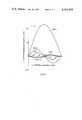
- FIG. 15 is a graphical representation indicating maximum nonconstant quantity with respect to plane cross-angle in the conventional tripod type constant velocity universal joint and in the tripod type constant velocity universal joint of this invention
- FIG. 16 is a graphical representation indicating non-constant velocity quantity with respect to phase angle in the conventional tripod type constant velocity universal joint and in the tripod type constant velocity universal joint of the invention
- FIGS. 17 and 18 are graphical representations indicating increase in whirling quantity in the conventional tripod type constant velocity universal joint and in the tripod type constant velocity universal joint of the invention.
- FIG. 19 is a sectional view of a part of a pot member, showing another modification of a roller race according to the present invention.
- FIG. 20 is a tabular representation of four examples shown in FIGS. 11, 12, 10 and 19.
- FIG. 1 is a perspective view showing the fundamental structure of the tripod type constant velocity universal joint.
- the tripod type constant velocity universal joint has a spider member 10.
- the spider member 10 has three roller supporting rods 11, 12 and 13 extended radially from the concentrated portion thereof in such a manner that the rods form angles of 120° with respect to one another.
- the spider member 10 is connected to one end of a first transmission shaft 14 (one of driving and driven shafts).
- Roller elements 15, 16 and 17 each having spherical outer surfaces are rotatably mounted on the roller supporting rods 11, 12 and 13 in such a manner that the roller elements are slidable on the rods, respectively.
- the roller elements 15, 16 and 17 are engaged with roller races (three pairs of roller raceways) 19, 20 and 21 formed in the cylindrical wall of a substantially cylindrical pot element 18, so that they can rotatably move in the roller races, respectively.
- roller races are in parallel with the axis of a second transmission shaft 22 (the other of the driving and driven shafts) connected to the pot member 18.
- FIG. 2 is a diagram providing a description of the constant velocity characteristic of the above-described tripod type constant velocity universal joint of the fundamental structure.
- the centers of the roller races in a plane perpendicular to the axis of the pot member, i.e. in a pot plane, will be designated by A 1 , A 2 and A 3 , respectively, and a circle whose circumference passes through the three points will be called "a master circle” (MC) having the center M.
- the mutual cross angles A 1 M, A 2 M and A 3 M are each 120°.
- a length A 1-3 M will be called "a pitch radius R.”
- the centers of the roller elements are on a slave ellipse (SE) obtained by projecting the master circle onto an XY plane, where points B 1 through B 3 correspond to the points A 1 through A 3 , respectively. Since the points B 1 through B 3 are on the three roller supporting rods spaced apart by 120° from one another, the connection point E (coincided with the axis of the first transmission shaft) of the three roller supporting rods is, in general, displaced by e from the intersection O of the XY plane, (coinciding with the axis of the second transmission shaft).
- FIG. 3 shows the case where the master circle is rotated by ⁇ around the axis y to be on the XY plane, and the center M' of the master circle thus rotated is moved toward the Y axis so that it is coincided with the intersection O of the XY plane.
- the relation between the rotational phase angles ⁇ and ⁇ is as follows, with the coordinates (a, b) of the roller supporting rod connection point E:
- the pitch radius R of the master circle defined by the distance from the rotational axis of said pot member to the longitudinal axis of each pair of roller raceways, is constant in the axial direction. Therefore, the rotational phase angle ⁇ is equal to the rotational phase angle ⁇ irrespective of the plane cross-angle of the pot member and the spider member; that is, the constant velocity characteristic can be obtained.
- FIG. 7 is a front view of the pot member thereof.
- the spider member 50 has a central part 55 having a spherical surface 51 and three end faces 52, 53 and 54 and three roller supporting rods 56, 57 and 58 which are respectively radially extended from the three end faces of the central part 55.
- Roller elements 59, 60 and 61 each having a spherical outer surface are rotatably supported on the roller supporting rods 56, 57 and 58 in such a manner that they can freely move along the rods, respectively.
- the ends of the roller supporting rods 56, 57 and 58 of the spider member 50 are fixedly secured to the inner wall of a bell-shaped housing 62.
- a tripod shaft 63 is integrally formed with the housing 62 in such a manner that it is extended from the housing along the axial line passing through the center of the central part 55.
- roller elements 59, 60 and 61 are so designed that they are movable along the roller supporting rods between the end faces of the central part 55 and the inner wall of the housing 62, and are engaged with roller races 65, 66 and 67 formed in the pot member 64; that is, they can rotatably move in the roller races, respectively.
- the pot member 64 is called “a tulip member” because of its configuration.
- a pot shaft 68 is extended from the bottom of the pot part of the pot member 64.
- the pot part receives the central part 55 of the spider member 50.
- the end portion of the pot member 64 is provided with a three-legged elastic member 69 which is formed so as to mount over the three pieces, between the above-described roller races, of the pot member, respectively.
- the three-legged elastic member 69 for preventing the relative sliding of the pot member 64 and spider member 50 in the axial direction thereof has a central portion which is slidably in contact with the spherical surface 51 of the spider member 50.
- the central part 55 of the spider member 50 has a hole 70 opened in its side opposite to the spherical surface 51.
- a depression pin 71 is fitted in the hole 70.
- a compression spring 72 is placed in the hole 70 so that the spring 72 causes the spherical head 73 of the depression pin 71 to abut against the internal bottom of the pot part and the spherical surface 51 to abut against the three-legged elastic member 69.
- roller races 65, 66 and 67 are formed in the cylindrical part of the pot part of the pot member 64 in such a manner that, as shown in FIG. 5, they are parallel with the axis of the pot member 64 to a predetermined point P, remote from the neutral point N, from the base point S, and are slightly inwardly bent over the distance between the predetermined point P and the top end point T.
- the bend of the top end region of the roller races as described above is called “one side modification of roller races.”
- FIG. 8 is an explanatory diagram similar to that of FIG. 3.
- the rotational phase angle ⁇ of the pot member is 30°.
- reference character C 1 designates a master circle in the parallel part of the roller races, the master circle C 1 having a maximum pitch radius R 0 defined by the distance from the rotational axis of said pot member to the longitudinal axis of each pair of roller raceways;
- C 2 is a master circle at the top end part of the roller races, the master circle C 2 being smaller in diameter than the master circle C 1 ;
- E 1 is the slave ellipse of the master circle C 1 ; and E 2 the slave ellipse of the master circle C 2 .
- FIG. 1 designates a master circle in the parallel part of the roller races, the master circle C 1 having a maximum pitch radius R 0 defined by the distance from the rotational axis of said pot member to the longitudinal axis of each pair of roller raceways;
- C 2 is a master circle at the top end part of the roller races, the master circle C 2 being smaller in diameter than the master circle C 1 ;
- E 1 is the slave ellipse of the master circle C 1
- each pair of roller raceways is modified so as to be inwardly inclined along straight lines on both sides thereof toward the rotational axis of a pot member by an approach quantity ⁇ , and the distances R between the longitudinal axis of each pair of roller raceways and the rotational axis of the pot member at both ends of the pair of roller raceways in the longitudinal direction are shorter than the distance R o therebetween at the central portion thereof within ⁇ of 0.2R o .
- modified joint has little nonconstant velocity quantity and can be easily assembled.
- FIG. 10 to FIG. 12 are diagrams of a part of a pot member, showing a roller race (a pair of roller raceways) which is subjected to symmetrical both-side modification according to the invention.
- the pair of roller raceways is in parallel with the axial line of the pot member 64 between points P 1 and P 2 which are equally spaced from the neutral point N of the pair of roller raceways in the opposite directions.
- the roller race (the pair of roller raceways) is inwardly bent at the points P 1 and P 2 in such a manner that the distance between the roller race and the axial line of the pot member 64 is shorter towards the top end point T on the top end side and the base point S on the base side than the parallel part of the roller race.
- the roller race is in the form of an arc which has its center on a line which is orthogonal with the axial line of the pot member and passes through the neutral point of the roller race. Accordingly, in this case also, the distance between the roller race and the rotational axis of the pot member 64 is the longest at the neutral point and is slightly shorter at the top end point T and the base point S.
- the roller race is so inwardly bent that the distance between the roller race and the rotational axis of the pot member 64 is the longest at the neutral point N and is gradually shortened towards the top end point T and the base point S from the neutral point N.
- FIG. 13 In the case of the tripod type constant velocity universal joint having the roller races subjected to both-side modification according to the invention, an explanatory diagram similar to that in FIG. 8 is as shown in FIG. 13.
- the roller centers are at the points A 1 , A 2 and A 3 of the master circle of the roller races, and at the points B 1 , B 2 and B 3 of the slave ellipse.
- the roller centers are at the points A 1 , A 2 ' and A 3 of the master circle of the roller races, and at the points B 1 , B 2 ' and B 3 of the slave ellipse, as shown in FIG. 13.
- the points A 1 and A 2 ' and the points B 1 and B 2 ' are symmetrical with respect to a Y axis. Accordingly, the rotational phase angle ⁇ of the pot member is equal to that ⁇ of the spider member; that is, the constant velocity characteristic is obtained.
- the both-side symmetrical modification of a pair of roller raceways can cancel the nonconstant velocity (velocity fluctuation) characteristic attributing to the one side modification by decreasing the differences of the pitch radiuses of the portions at which two adjacent roller elements are respectively located in the pairs of roller raceways, (for example, one roller element being located at one bent portion of a pair of roller raceways, and the other roller element being located at the other bent portion thereof) and by increasing the frequency of the nonconstant velocity (velocity fluctuation) and the zero timings of the quantities of nonconstant velocity, and can greatly reduce the quantity of nonconstant velocity.
- the quantity of nonconstant velocity of the tripod type constant velocity universal joint having the roller races subjected to both-side symmetrical modification is fluctuated in a sixth order pattern of revolution.
- the inventors prepared six tripod type constant velocity universal joints with roller races which respectively have different modified patterns and compared differences in nonconstant velocity quantity, whirling quantity and roller stroke quantity attributed to differences in modification patterns with one another.
- the various data of the six tripod type constant velocity universal joints thus prepared are as indicated in FIG. 14.
- Case 0 of FIG. 14 The data indicated in Case 0 of FIG. 14 is for the conventional tripod type constant velocity universal joint having roller races subjected to one side modification.
- Case 1 corresponds to the example shown in FIG. 10.
- Case 2 corresponds to the example shown in FIG. 11.
- Cases 3 through 5 correspond to the example shown in FIG. 12.
- Each approach quantity ⁇ of Cases 1 to 5 is as shown in the data of FIG. 14.
- FIG. 15 is a graphical representation indicating quantities of maximum nonconstant velocity with respect to plane cross-angles ⁇ respectively according to the Cases.
- the modification pattern is symmetrical with respect to the neutral point, i.e. the center of the joint of the roller race (note comparison of Case 0 with Cases 1 through 5).
- the modification pattern have no parallel part with respect to the rotational axis of the pot member (comparison of Case 1 with Case 4), because in Case 1, the pitch radius R of the parallel part having a predetermined length is maximum, and the differences of the pitch radiuses of the portions at which two adjacent roller elements are respectively located in the pairs of roller raceways are relatively increased in comparison with Case 4.
- the modification pattern is in the form of a straight line instead of an arc (comparison of Case 2 with Cases 1, 3, 4 and 5), because in Case 2 having arc shape roller raceways, tangential directions of the shape of the roller raceways at both end portions with respect to the rotational axis of the pot member become large, so that the differences of the pitch radiuses of the portions at which two adjacent roller elements are respectively located in the pairs of roller raceways are relatively increased in comparison with Cases 1, 3, 4 and 5.
- the quantity of the modification i.e., the approach quantity ⁇ of the pair of roller raceways with respect to the rotational axis of the pot member, becomes as small as possible, because in Case 3, the approach quantity ⁇ is the shortest of all Cases, so that the differences of the pitch radius of the portions at which two adjacent roller elements are respectively located in the pairs of roller raceways are the most reduced.
- the approach quantity ⁇ is selected from the range of ⁇ 0.2R 0 in view of the quantity of nonconstant velocity, size and easy assembling, wherein R 0 is a maximum pitch radius defined by the distance from the rotational axis of the pot member to the longitudinal axis of each pair of roller raceways.
- each pair of roller raceways is provided along the arc line having a predetermined large radius r B of curvature and length and passing through the neutral point N of the pair of roller raceways, and is provided along the straight lines having a predetermined angle to the rotational axis of the pot member and connecting spaced points P 1 ', P 2 ' from the neutral point and both ends S, T of the pair of roller raceways, so that the approach quantity ⁇ is shorter than that of Case 3 and the differences of the pitch radius of the portions at which two adjacent roller elements are respectively located in the pairs of roller raceways are further reduced than in Case 3.
- the invention is intended to provide a tripod type constant velocity universal joint in which the roller races are subjected to slight both-side symmetrical modification with the neutral point as the symmetry point within a predetermined approach quantity ⁇ thereby to greatly lower the conconstant velocity characteristic when compared with that of the conventional joint subjected to one side modification and the others.
- the whirling quantity is decreased by about 0.055-0.165 mm in the direction of the major axis of the elliptic locus and by about 0-0.075 mm in the direction of the minor axis.
- the whirling motion forcibly generates vibration and noise. Accordingly, such vibration and noise can be decreased by reducing the whirling quantity.
- the inside diameter of the housing can be decreased as much, with the result that the universal joint can be designed to be small in size.
- maximum value is intended to mean the distance between the roller center and the base of the roller supporting rod obtained when the roller element is positioned closest to the top end of the roller supporting rod;
- minimum value is intended to mean the distance between the roller center and the base of the roller supporting rod obtained when the roller element is positioned closest to the base of the roller supporting rod;
- stroke quantity is intended to mean a value obtained by subtracting the minimum value from the maximum value.
- roller stroke quantity between the conventional universal joint (Case 0) and the universal joint of the invention is as follows: the roller stroke quantity of each of the universal joints of the invention is smaller than that of the conventional one. Especially in Case 4, the roller stroke quantity of the universal joint of the invention is smaller by about 20% than that of the conventional one. If the maximum value of the roller stroke is reduced, the inside diameter of the housing can be decreased.
- the positions of the end faces of the central part 55 of the spider member can be shifted outwardly as much, whereby the area of the spherical surface of the spider member can be increased, with the result that the three-leg elastic member rarely comes apart from the spherical surface, and the maximum operating joint angle can be increased.
- a comparison in roller element movement amount between the conventional universal joint (Case 0) and the universal joints of the invention (Cases 1 through 5) is as follows: the amount of movement of any one of the universal joints of the invention is smaller than that of the conventional one. This will reduce the number of times where there is a chance that the roller elements will be removed from the respective roller races, and it furthermore suggests the possibility that the universal joint can be so designed as to be small in size and light in weight.
- the above-described effect means that, in the case where the size of the universal joint is predetermined, the maximum operating joint angle of the universal joint can be increased, so that the rotation radius of the front driven vehicle can be decreased.
- the maximum pitch radius R o is 19.9 mm and the approaching quantity ⁇ is 0.2 R o , i.e. 3.98 mm.
Landscapes
- Engineering & Computer Science (AREA)
- General Engineering & Computer Science (AREA)
- Mechanical Engineering (AREA)
- Rolling Contact Bearings (AREA)
Abstract
Description
              TABLE 1
______________________________________
Roller stroke
                             (γ = 41°)
     Maximum value
                 Minimum value
                             Stroke quantity
Case Smax (mm)   Smin (mm)   (Smax - Smin) (mm)
______________________________________
0    29.58       16.75       12.83
1    27.71       16.83       10.88
2    27.752      16.804      10.948
3    27.570      16.836      10.734
4    26.946      16.883      10.063
5    27.672      17.338      10.334
______________________________________
              TABLE 2
______________________________________
Movement
      Maximum value
                  Minimum value
                              Amount of (γ = 41°)
Case  (mm)        (mm)        movement (mm)
______________________________________
0     18.192      -19.406     37.598
1     18.184      -18.184     36.368
2     18.207      -18.207     36.414
3     18.088      -18.088     36.176
4     17.678      -17.678     35.356
5     18.154      -18.154     36.308
______________________________________
Claims (14)
Applications Claiming Priority (3)
| Application Number | Priority Date | Filing Date | Title |
|---|---|---|---|
| JP53-113122 | 1978-09-14 | ||
| JP11312278A JPS5540350A (en) | 1978-09-14 | 1978-09-14 | Tri-port type constant speed universal joint |
| EP79103455.6 | 1979-09-14 |
Related Parent Applications (1)
| Application Number | Title | Priority Date | Filing Date |
|---|---|---|---|
| US06073872 Continuation-In-Part | 1979-09-10 |
Publications (1)
| Publication Number | Publication Date |
|---|---|
| US4421494A true US4421494A (en) | 1983-12-20 |
Family
ID=14604070
Family Applications (1)
| Application Number | Title | Priority Date | Filing Date |
|---|---|---|---|
| US06/239,464 Expired - Fee Related US4421494A (en) | 1978-09-14 | 1981-03-02 | Tripod type constant velocity universal joint |
Country Status (4)
| Country | Link |
|---|---|
| US (1) | US4421494A (en) |
| EP (1) | EP0009224B1 (en) |
| JP (1) | JPS5540350A (en) |
| DE (1) | DE2967054D1 (en) |
Cited By (5)
| Publication number | Priority date | Publication date | Assignee | Title |
|---|---|---|---|---|
| US5127881A (en) * | 1989-11-13 | 1992-07-07 | Glaenzer Spicer | Constant-velocity joint with an axially retained tripod |
| US5569089A (en) * | 1993-10-28 | 1996-10-29 | Signorelli; Richard L. | Universal joint construction |
| US5645487A (en) * | 1992-05-01 | 1997-07-08 | Gkn Automotive Ag | Constant velocity ratio universal joint of the tripode type |
| US6195973B1 (en) * | 1998-06-19 | 2001-03-06 | Claas Saulgau Gmbh | Hay making machine with improved shaft coupling |
| US20140206460A1 (en) * | 2011-07-08 | 2014-07-24 | Somfy | Coupling device, and home automation equipment including such a device |
Families Citing this family (1)
| Publication number | Priority date | Publication date | Assignee | Title |
|---|---|---|---|---|
| FR2703119B1 (en) * | 1993-03-23 | 1995-06-16 | Glaenzer Spicer Sa | ARTICULATED TRANSMISSION JOINT. |
Citations (7)
| Publication number | Priority date | Publication date | Assignee | Title |
|---|---|---|---|---|
| US3818721A (en) * | 1972-09-15 | 1974-06-25 | Wahlmark Systems | Constant velocity universal drive |
| US3877251A (en) * | 1973-06-15 | 1975-04-15 | Wahlmark Systems | Universal joint system |
| US4010625A (en) * | 1974-09-27 | 1977-03-08 | Glaenzer Spicer | Sliding homokinetic joint |
| US4167860A (en) * | 1976-12-20 | 1979-09-18 | Toyota Jidosha Kogyo Kabushiki Kaisha | Universal joint |
| US4175407A (en) * | 1977-03-04 | 1979-11-27 | Glaenzer Spicer | Homokinetic joint allowing a large angular displacement |
| US4178778A (en) * | 1977-03-04 | 1979-12-18 | Glaenzer Spicer | Homokinetic joint of the tripod type |
| US4205539A (en) * | 1977-07-28 | 1980-06-03 | Glaenzer Spicer | Axially-retained tripod homokinetic joint |
Family Cites Families (7)
| Publication number | Priority date | Publication date | Assignee | Title |
|---|---|---|---|---|
| FR84753E (en) * | 1963-01-04 | 1965-04-16 | Citroen Sa Andre | Improvement in constant velocity joints |
| GB1272053A (en) * | 1969-02-26 | 1972-04-26 | Peugeot | Improvements in or relating to a universal joint |
| FR2049283A5 (en) * | 1969-06-05 | 1971-03-26 | Peugeot & Renault | |
| FR2169450A5 (en) * | 1972-01-25 | 1973-09-07 | Glaenzer Spicer Sa | |
| FR2298035A1 (en) * | 1975-01-17 | 1976-08-13 | Glaenzer Spicer Sa | HOMOCINETIC JOINT WITH AXIAL RETENTION |
| JPS5222056A (en) * | 1975-08-13 | 1977-02-19 | Sumitomo Electric Industries | Thermoplastic resin extruder |
| US4083202A (en) * | 1976-08-05 | 1978-04-11 | General Motors Corporation | Stroking universal joint housing |
-
1978
- 1978-09-14 JP JP11312278A patent/JPS5540350A/en active Pending
-
1979
- 1979-09-14 EP EP79103455A patent/EP0009224B1/en not_active Expired
- 1979-09-14 DE DE7979103455T patent/DE2967054D1/en not_active Expired
-
1981
- 1981-03-02 US US06/239,464 patent/US4421494A/en not_active Expired - Fee Related
Patent Citations (7)
| Publication number | Priority date | Publication date | Assignee | Title |
|---|---|---|---|---|
| US3818721A (en) * | 1972-09-15 | 1974-06-25 | Wahlmark Systems | Constant velocity universal drive |
| US3877251A (en) * | 1973-06-15 | 1975-04-15 | Wahlmark Systems | Universal joint system |
| US4010625A (en) * | 1974-09-27 | 1977-03-08 | Glaenzer Spicer | Sliding homokinetic joint |
| US4167860A (en) * | 1976-12-20 | 1979-09-18 | Toyota Jidosha Kogyo Kabushiki Kaisha | Universal joint |
| US4175407A (en) * | 1977-03-04 | 1979-11-27 | Glaenzer Spicer | Homokinetic joint allowing a large angular displacement |
| US4178778A (en) * | 1977-03-04 | 1979-12-18 | Glaenzer Spicer | Homokinetic joint of the tripod type |
| US4205539A (en) * | 1977-07-28 | 1980-06-03 | Glaenzer Spicer | Axially-retained tripod homokinetic joint |
Cited By (6)
| Publication number | Priority date | Publication date | Assignee | Title |
|---|---|---|---|---|
| US5127881A (en) * | 1989-11-13 | 1992-07-07 | Glaenzer Spicer | Constant-velocity joint with an axially retained tripod |
| US5645487A (en) * | 1992-05-01 | 1997-07-08 | Gkn Automotive Ag | Constant velocity ratio universal joint of the tripode type |
| US5569089A (en) * | 1993-10-28 | 1996-10-29 | Signorelli; Richard L. | Universal joint construction |
| US6195973B1 (en) * | 1998-06-19 | 2001-03-06 | Claas Saulgau Gmbh | Hay making machine with improved shaft coupling |
| US20140206460A1 (en) * | 2011-07-08 | 2014-07-24 | Somfy | Coupling device, and home automation equipment including such a device |
| US9057408B2 (en) * | 2011-07-08 | 2015-06-16 | Somfy Sas | Coupling device, and home automation equipment including such a device |
Also Published As
| Publication number | Publication date |
|---|---|
| DE2967054D1 (en) | 1984-07-19 |
| JPS5540350A (en) | 1980-03-21 |
| EP0009224A1 (en) | 1980-04-02 |
| EP0009224B1 (en) | 1984-06-13 |
Similar Documents
| Publication | Publication Date | Title |
|---|---|---|
| US6533668B2 (en) | Constant velocity joint of tripod type | |
| KR101024883B1 (en) | Tripod type constant velocity joint | |
| US6776720B2 (en) | Tripode constant velocity joint | |
| US3381497A (en) | Universal joint | |
| GB2195167A (en) | Universal joints | |
| GB2226102A (en) | Constant velocity ratio universal joint of the tripod type | |
| US4421494A (en) | Tripod type constant velocity universal joint | |
| JP2006283828A (en) | Tripod type constant velocity universal joint | |
| JP3467051B2 (en) | Positioning spring for positioning a plurality of rollers of a triplan joint and a triplan joint using the same | |
| US6764406B2 (en) | Constant velocity joint of tripod type | |
| US5098342A (en) | Tripod type constant velocity joint | |
| US3965700A (en) | Drive line coupling device with substantially homokinetic features | |
| CA1124534A (en) | Constant velocity universal joint | |
| US4846764A (en) | Constant velocity joint cage and method for making same | |
| US6264565B1 (en) | Tripod type constant velocity universal joint | |
| KR900000651B1 (en) | Homokinetic tripod joint | |
| US8251828B2 (en) | Constant velocity joint | |
| JPH0814289B2 (en) | Telescopic report universal joint | |
| JPH05231435A (en) | Constant velocity universal joint | |
| JPS61116126A (en) | Tripod type equi-velocity joint | |
| US5415588A (en) | Wide angle universal joint | |
| US20210301879A1 (en) | Constant velocity joint | |
| ES488718A1 (en) | Coil spring having a small axial and radial overall size | |
| JPH0623574B2 (en) | Universal joint | |
| JPS628664Y2 (en) |
Legal Events
| Date | Code | Title | Description |
|---|---|---|---|
| AS | Assignment |
Owner name: TOYOTA JIDOSHA KOGYO KABUSHIKI KAISHA 1, TOYOTA-CH Free format text: ASSIGNMENT OF ASSIGNORS INTEREST.;ASSIGNORS:FUTAMURA, YOSHISUMI;KOMEIJI, SHIGEKI;NORO, SHUHEI;AND OTHERS;REEL/FRAME:004119/0193 Effective date: 19810212 Owner name: KABUSHIKI KAISHA TOYOTA CHUO KENKYUSHO 41-1, AZA Y Free format text: ASSIGNMENT OF ASSIGNORS INTEREST.;ASSIGNORS:FUTAMURA, YOSHISUMI;KOMEIJI, SHIGEKI;NORO, SHUHEI;AND OTHERS;REEL/FRAME:004119/0193 Effective date: 19810212 |
|
| CC | Certificate of correction | ||
| FEPP | Fee payment procedure |
Free format text: PAYOR NUMBER ASSIGNED (ORIGINAL EVENT CODE: ASPN); ENTITY STATUS OF PATENT OWNER: LARGE ENTITY |
|
| MAFP | Maintenance fee payment |
Free format text: PAYMENT OF MAINTENANCE FEE, 4TH YEAR, PL 96-517 (ORIGINAL EVENT CODE: M170); ENTITY STATUS OF PATENT OWNER: LARGE ENTITY Year of fee payment: 4 |
|
| MAFP | Maintenance fee payment |
Free format text: PAYMENT OF MAINTENANCE FEE, 8TH YEAR, PL 96-517 (ORIGINAL EVENT CODE: M171); ENTITY STATUS OF PATENT OWNER: LARGE ENTITY Year of fee payment: 8 |
|
| FEPP | Fee payment procedure |
Free format text: MAINTENANCE FEE REMINDER MAILED (ORIGINAL EVENT CODE: REM.); ENTITY STATUS OF PATENT OWNER: LARGE ENTITY |
|
| LAPS | Lapse for failure to pay maintenance fees | ||
| FP | Lapsed due to failure to pay maintenance fee |
Effective date: 19951220 |
|
| STCH | Information on status: patent discontinuation |
Free format text: PATENT EXPIRED DUE TO NONPAYMENT OF MAINTENANCE FEES UNDER 37 CFR 1.362 |