US442000A - Device for utilizing the water-power of falls - Google Patents
Device for utilizing the water-power of falls Download PDFInfo
- Publication number
- US442000A US442000A US442000DA US442000A US 442000 A US442000 A US 442000A US 442000D A US442000D A US 442000DA US 442000 A US442000 A US 442000A
- Authority
- US
- United States
- Prior art keywords
- dam
- falls
- water
- cotter
- power
- Prior art date
- Legal status (The legal status is an assumption and is not a legal conclusion. Google has not performed a legal analysis and makes no representation as to the accuracy of the status listed.)
- Expired - Lifetime
Links
Images


Classifications
-
- E—FIXED CONSTRUCTIONS
- E02—HYDRAULIC ENGINEERING; FOUNDATIONS; SOIL SHIFTING
- E02B—HYDRAULIC ENGINEERING
- E02B9/00—Water-power plants; Layout, construction or equipment, methods of, or apparatus for, making same
-
- Y—GENERAL TAGGING OF NEW TECHNOLOGICAL DEVELOPMENTS; GENERAL TAGGING OF CROSS-SECTIONAL TECHNOLOGIES SPANNING OVER SEVERAL SECTIONS OF THE IPC; TECHNICAL SUBJECTS COVERED BY FORMER USPC CROSS-REFERENCE ART COLLECTIONS [XRACs] AND DIGESTS
- Y02—TECHNOLOGIES OR APPLICATIONS FOR MITIGATION OR ADAPTATION AGAINST CLIMATE CHANGE
- Y02E—REDUCTION OF GREENHOUSE GAS [GHG] EMISSIONS, RELATED TO ENERGY GENERATION, TRANSMISSION OR DISTRIBUTION
- Y02E10/00—Energy generation through renewable energy sources
- Y02E10/20—Hydro energy
Definitions
- n mams rams cox, mam-11mm, wnsmuumu, n. c.
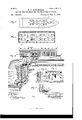
- Figure l is a perspective view of the American side of the Falls of Niagara, and shows the cotter-dam s, their cable-moorage, and guystays.
- Fig. 2 is an enlarged top view of one of the cotter-dams, showing details of the lower deck fore and aft, and broken away amidship to show the detachable angle-iron, bilge-sills, and steel bilge-plates of the removable bottom of said cotter-dam. It also shows on the forecastle-deck the Windlassdrum that carries, winds up, and pays out the moorage-cable.
- Fig, 3 is alike view of the cotterdam on the lower deck or below deck and shows the turbine wheels within the wheelchamber, the suction sluiceway through the quarterturn draft-tubes, and the bevel pinion-gear that transfers the power generated by the turbines to the shafts that work the friction-generators for the electric dynamos or other suitable motor-power.
- Fig. i is a side View of one of the cotter-dams, and shows the steelplate sheeting that covers the hull, the grated inlet to one of the waterways to the turbine-wheel chamber on that side the cotter-dam, and the gunwale-sheavcs that guide the mooring and guy cables as they are paid out and drawn in.
- Fig. 5 is a transverse vertical section taken 011 line V V, Fin. 2, and shows the wheel-chambers in the Coffer-dam with the flood-gates elevated to let on the water to the turbines.
- Fig. 6 is a like view, taken on line IV IV, Fig.
- FIG. 3 shows the flood-gates elevated, the sluiceways into the turbine-chambers, the turbine wheels, the suction quarter-turn pipes from the turbines, the tailrace shaft into which said pipes discharge, and the bevel pinion-gear that transfers the power from the turbine-shafts to the drive-shatts of the dyuamos.
- Fig. 7 is a detail section taken on line VII VII, Fig. 10 and shows the cotter-darn, the tailrace shaft, the angle drift-shaft that leads toward the outlet-pipe at the foot of the falls.
- FIG. 8 It also shows a transverse section of the structure above the cotter-dam, and the belted and friction means of transmitting power from the turbines to the dynamo;
- Fig.8 a top view of one of the cotter-dams, and shows the lower tier of dynamos on the lower deck of said Coffer-dam;
- Fig. 9, a horizontal section taken on line IX IX, Fig. 10, and shows the upper deck, the surmounting structure above said deck, the system of dynamos, and the endless drive-belts thattranst'er power from the drivepulley drum of the lower drive-shaft to that of the upper drive-shaft.
- Fig. 9 a transverse section of the structure above the cotter-dam, and the belted and friction means of transmitting power from the turbines to the dynamo;
- Fig.9 a top view of one of the cotter-dams, and shows the lower tier of dynamos on the lower deck of said Coffer-dam
- Figl l is an enlarged detail view of one of the skirting plates, its loweredge out to fit the irregularities in the bed-rock.
- Fig. 12 is an enlarged end or edge view and shows the skirting plates cut to fit irregularities in the bedrock, the said plates being held by the springfork while lowering and while being riveted or bolted above the water-mark to the hull of the cotter-dam and to its incasement-jacket.
- FIG. 13 is an enlarged detail section vertical of one of the angle-iron detachable bilge-sills, the steel-bottom bilge-plates, and a side rib of the hull of the coffer-daul to which said detachable bilgesills and steel plates are at a plan View of a modification in which the cable-moorage is effected direct from a projecting promontory upstream. It also shows the cotter-dam guyed both fore and aft.
- Fig. 15 is an enlarged vertical detail section of the stanchion attachment.
- Fig. 16 is a modification, showing the tailrace running in a straight line from the Coffer-dam into the river below the falls.
- 1 represents the hull of the cotter-dam, the frame of which is constructed with side ribs-2 and bottom or bilge sills 3.
- Steel plates 4 are secured to said side ribs 2 of the hull by the rivets 5 and similar plates 7, and a like number are secured-by rivets, also numbered 5, to the outer angle-flange of the double-flanged bracketribs 6, whose-inner flanges 8 are secured to the outs-ides'of the steel plates 4 of the hullv of the coifer-dam'also by rivets numbered 5.
- bracket-ribs increase inm'dt-h from the top to the bottom of the cotter-dam, and thus leave an intervening spacebetween the hull of the cotter-dam and itssurroundingincasement-jacket formed by the plates 7, that flare outwardly fromthe hull from the top to the bottom.
- the Coffer-dams are builtof any suitable size adapted to the power to be developed, and are approximated to the shape of a flatboat.
- cotter-dam and its incasement-jacket are located two fiume chambers 11, one on each side, that pass through both the casing and the hull, the ports 12 of which flumes are pro-- Near the aft or stem of the hull of thearound which Windlass is wound the cable 18, which adjustsa-nd holds the coffer-dam longitudinally to its position in the river.
- guy-cables are secured to strongmetal columns or stanchions 60 on the banks of the river or islands.
- a transverse cable 23 may be secured at each end on the opposite banksof the river or branch of the river above the falls, as-show n inFig. 1, in which, to illustrate the applicationof the invention, is-presented aview ot' the American side of the Niagara river above-the Falls'of Niagara.
- the stanchions may be then secured by bolts 26, that pass through said collar flanges 25, and are seated in drilled holes'27 in the rock 28 beneath, and which are fastened therein by wedges 29,entered in the split lower ends 30 of said bolts, which, as they engage against the bottom of the drillholes, are driven up within the split of the bolts, which are thus expanded at the. lower ends and firmly clamped in said drill-holes.
- Windlass-drums of both the moorage and guy cables may bedriven on each cofferda'm by a donkey-engine or other engine, the
- transverse moorage-cable secured at one end toa stanchion 24 ot the American bank of the river above the falls, and at the other end to a stanchion on Goat Island, to which transverse cable, as stated, the individual moorage" cables 18 from the bows ot' the cotter-dams are secured at various points 26 along said trans- Verse cable; but I do not confine myself to said means of in a measure indirect moorage, for, as is the case in the American branch of Niagara river, there is a turn in the course of the stream above the falls, I may then effect the moorage of the coffer-dams by individual direct nioorage-cables, as shown in Fig.
- Windlass-drums that carry the moor-age and guy cables, also the drive-gear and the power that operates the same as on the cotter-dams themselves; but I do not thus confine myself, for the Windlass-drums and the power-gear that works the same may be, and in certain cases it would preferably be, located on the bank or banks of the river, or on islands in the stream, at the reverse ends of said cables.
- the coffers are all held until planted by direct moorage-cables from the one stanchion-column, as shown in Fig. 14, I prefer to provide a system of guy-ropes aft, as shown in broken lines in said figure, as well as forward,as shown in full lines, so as to bring the adjustment of said coffers in direct line with the course of the stream, the said guy-cables being secured to stanchion-columns planted in suitable positions either on the banks of the river or on islands in mid-stream.
- the coffer-dan1s may be launched upstream in the immediate vicinity of the stanchioncolumn or other lnoorage-stay that holds the ground'end of the moorage-cable, and then drifted downstream to the location where they are to be sunk and where they are held captive until securely grounded on the bed-rock, the guy-cables at the same time being secured and adjusted to locate the lateral position of the coffer. Otherwise the coffer-damsnnay be launched broadside on about opposite their ultimate location, the moorage-cable being socurely attached before launching, so as to hold the cotter-dam captive. The guy-cables are then adjusted to swing the coifer in the stream to the lateral position required.
- the Windlass-drums that carry the moorage and guy cables are to be kept under the control of the engines until the above-described location of the cotter-dams has been effected.
- the locking-dogs 31 are then brought into engagement with the drums of the mooragewindlasses and similar locking-dogs 32 into engagement with the drums of the guy-windlasses, thus securely holding the cables, and through them the cotter-dams, in their adjusted captive position. If the cotter-dam has been allowed to drift down too far, the moorage-windlass drums may be turned by the application of power from the said e11- gines and the moorage-cables wound up thereon until the coffer has attained or regained its required position.
- Suitable connectinggears and pulley-belting from the engines to the rotary pumps 33 are then started, and water is thus pumped in to the hold of the coiferdams until they are suii'lciently weighted to sink them to the bedrock beneath the river.
- the depth In a suitable position for the location of the cofier-dams above the Falls of Niagara the depth generally ranges in the neighborhood of twelve feet.
- One series is placed outside the hull-plates and the other series inside the plates of the incasement-jacket, and they are respectively secured by rivets 38, that are seated in perforations 39 in said skirtplates and in the hull and incaselnent jacket plates above the water-line, as shown in Figs. 11 and 12.
- the prongs of the spring-forks are seated in the brackets 37, that are riveted to the skirtplates near their lower edges before the skirtplates are lowered to position.
- the said spring-forks are constructed with double shanks that have an elastic tendency to spring apart, so that as the sheathing of the incasement-jacket flares outwardly from that of the hull toward the bottom, as shown in Figs. 5, 6, and 7, so as to widen the intervening space as it approaches the bed-rock, the prongs of the spring-forks also expand,
- the spring-forks may be removed and laid away forfuture use. It is evident that, as the concrete is soft when it is laid in its bed on the bed-rock of the river and within the mold formed by the hull on the inside and the incasing-jacketon the outside, the said concrete accommodates itself to all the inequalities of the bedrock, and forms in consequence a water-tight foundation and surmounting wall, whichas it hardens becomes integral with the bed-rock of the river on which his laid, and so firmly unites with it and is cemented to the rough surface of said bed-rock, as also to the hull and incasing-jacket of the coffer-dam, as to hold said Coffer-dam from displacement.
- the additional weight thus added to the structure also adds greatly to the firm anchorage of the same upon the bed-rock, and its steelcladisides protect the surface of the molded concrete wall and re-enforce the strength of the structure.
- the rotary pumps are next reversed in position,the suction-pipes 41, that were previously passed over the bulwarks of the incasing-jackets of the coffer-dams and passed down into the river alongside, and the rotary head of the pump discharging into the hold now changing position the suctionpipes being now placed in the holds of the coffer-dams and the rotary heads projecting and discharging over the bulwarks into the river to empty the water from the hold.
- the rotary pump may be driven by the usual endless drive-belts from the engines that drive the windlass-dru ms, which belts engage with the drive-pulleys 42 on the projecting journal-shafts 43 of the radial suction-buckets of the pumps to eifect the working of the same.
- a vertical shaft 45 whose diameter is regulated in accordance with the amount of water that is to be passed through the flumes,is sunk in the rock to the depth required.
- the shaft is drifted horizontally outward at 46 until it finds vent in front of the precipice over which the falls are precipitated. (See Figs. 7 and 10.)
- the vertical tubular cylinder 47 In said vertical and horizontal shafts in the rock is placed the vertical tubular cylinder 47 the horizontal tubular cylinder 48, and the quarter-turn tubular cylinder49.
- a second quarter-turn tubular cylinder 50 connects the outer end of the horizontal tubular cylinder 48 with the vertical pendent tubular cylinder 51, the bottom of which is immersed in the water 14 at the foot of the falls, thus consti tuting a water seal at the discharge end of the cylinder that prevents the ascent of air through said cylinder, and thus makes of the tail-race a suction-race or reverse draw-head from the turbines in the flumes.
- Cross drive-belts 65 are mounted on the pulleys 66 on the drive-shaft 62 and engage with the pulleys 67 on the shafts 68 of the dynamos (59, that are located on the lower deck, the belts preferably angling crosswise, respectively, those from the pulleys on the larboard side of the coffer-dam to the dynainos on the starboard side, and vice versa.
- frictional rolls 7 0 may be used that convey rotary movement from the drive-wheels 71 to the friction-pulleys 67 on the dynamo-shafts that vertically surmount them.
- Said shafts 76 also carry the individ ual drive-wheels 78, from which the belts 79 cross and engage with and drive the pulleys 80 on the individual shafts SI of the dynainos 82, which dynamics are located on or above the upper floor, and thus the cross-belts from the drive-wheels 78 on the larboard or port side of the cotter-dam, respectively, drive the dynamo-pulleys on the starboard or righthand side, and the drive-wheels on the starboard side with their cross-belts operate vice versa.
- friction gear wheels or rolls which may be used as transmitters in the place of the beltedcross-gear, and in such case may be mounted on any suitable adj ustable bearings that allow them to be thrown into and out of gear, as the case may be.
- the said friction gear-wheels transmit the movement from the individual drive-wheels 85, which in this modified form take the place of the individual drive-wheels 78, being mounted on the said shafts 76, which carry the drums 75, and thus is etfected a direct transmission of the power.
- the journal-bearings of said shafts are lowered, as shown on the starboard or right-hand side in Fig. 7, so as to adjust them to their friction-gear in contradistinction to their belted gear.
Landscapes
- Engineering & Computer Science (AREA)
- General Engineering & Computer Science (AREA)
- Mechanical Engineering (AREA)
- Civil Engineering (AREA)
- Structural Engineering (AREA)
- Other Liquid Machine Or Engine Such As Wave Power Use (AREA)
Description
5 Sheets-Sheet 1.
(No Model.)
G. J. ZEITINGER.
DEVICE FORUTILIZING THE WATER POWER OF FALLS.
Patented Dec. 2, 1890.
08 0 530 ggq 91 0 0 9 Witnesses:
(No Model.) 5 SheetsSheet 2.
G. J. ZEITINGER. DEVICE FOR UTILIZING THE WATER POWER OF FALLS.
I Patented Dec. 2, 1890.
fittornqys.
Ipz/entqr:
m: mams rams cox, mam-11mm, wnsmuumu, n. c.
5 Sheets-Sheet 3.
Patented Dec. 2, 1890.
O. J. ZEITINGER.
(No Model.)
DEVICE FOR UTILIZING THE WATER POWER OI FALLS.
(No Model.) 5 Sheets-Sheet 4. 0. J. ZEITINGER. DEVICE FOR UTILIZING THE WATER POWER. OI FALLS.
Patented Dec. 2, 1890.
fittoz'rl ys.
ma "cams warns on, wovmunm, wnsumlirou. o, c.
No Model.) 5 Sheets-Sheet 5. C. J. ZEITINGER. DEVICE FOR UTILIZING THE WATER POWER OF FALLS. No. 442,000. Patented Dec. 2, 1890.
.. I MW E2 we Noam: PETiRS coi, PMOYWLITHLL, msmamn, n. n,
{Hai
MEI IEWEME- UNITED STATES PATENT OFFICE.
CHRISTIAN J. ZEI'IINGER, OF ZEITONIA, MISSOURI.
DEVICE FOR UTILIZING THE WATER-POWER OF FALLS.
SPECIFICATION forming part of Letters Patent No. 442,000, dated December 2, 1890.
Application filed April 19,1890. Serial No. 348,720. (No model.)
To all whom it may concern:
Be it known that I, CHRISTIAN J ZEITINGER, of the city of Zeitonia, in the county of Vayne and State of Missouri, have invented certain new and useful Improvements in Devices for Utilizing Water-Power of Falls, of which the following is a full, clear, and exact description, reference being bad to the accompanying drawings, forming part of this specification.
- lhe in ventionrelates to devices for utilizing the at present waste power thatis engendered by the descent of water in the vicinity of natural falls; and the invention consists in featuresof novelty herein after fully described, and pointed out in the claims.
Figure l is a perspective view of the American side of the Falls of Niagara, and shows the cotter-dam s, their cable-moorage, and guystays. Fig. 2 is an enlarged top view of one of the cotter-dams, showing details of the lower deck fore and aft, and broken away amidship to show the detachable angle-iron, bilge-sills, and steel bilge-plates of the removable bottom of said cotter-dam. It also shows on the forecastle-deck the Windlassdrum that carries, winds up, and pays out the moorage-cable. On the detailof the deck aft is shown the rotary pumps and their suction'pipes by which the hold of the cofferdam is either respectively flooded or emptied of water. The side-guy cable-drums and the bevehgear that drives the cable-moorage and guy-drums are also shown, and in outline the turbine chambers and entrance to the tailrace shaft. Fig, 3 is alike view of the cotterdam on the lower deck or below deck and shows the turbine wheels within the wheelchamber, the suction sluiceway through the quarterturn draft-tubes, and the bevel pinion-gear that transfers the power generated by the turbines to the shafts that work the friction-generators for the electric dynamos or other suitable motor-power. It also shows the abutting masonary built up from the bed rock in the bottom of the cotter-dam. Fig. i is a side View of one of the cotter-dams, and shows the steelplate sheeting that covers the hull, the grated inlet to one of the waterways to the turbine-wheel chamber on that side the cotter-dam, and the gunwale-sheavcs that guide the mooring and guy cables as they are paid out and drawn in. Fig. 5 is a transverse vertical section taken 011 line V V, Fin. 2, and shows the wheel-chambers in the Coffer-dam with the flood-gates elevated to let on the water to the turbines. Fig. 6is a like view, taken on line IV IV, Fig. 3, and shows the flood-gates elevated, the sluiceways into the turbine-chambers, the turbine wheels, the suction quarter-turn pipes from the turbines, the tailrace shaft into which said pipes discharge, and the bevel pinion-gear that transfers the power from the turbine-shafts to the drive-shatts of the dyuamos. Fig. 7 is a detail section taken on line VII VII, Fig. 10 and shows the cotter-darn, the tailrace shaft, the angle drift-shaft that leads toward the outlet-pipe at the foot of the falls. It also shows a transverse section of the structure above the cotter-dam, and the belted and friction means of transmitting power from the turbines to the dynamo; Fig.8, a top view of one of the cotter-dams, and shows the lower tier of dynamos on the lower deck of said Coffer-dam; Fig. 9, a horizontal section taken on line IX IX, Fig. 10, and shows the upper deck, the surmounting structure above said deck, the system of dynamos, and the endless drive-belts thattranst'er power from the drivepulley drum of the lower drive-shaft to that of the upper drive-shaft. Fig. 10 is a detail elevation, part in section and part broken away to show the interior arrangements for engendering and transmitting power, and shows the coifei dam, the structureabove the same, also the tailrace, the drift-shaft, and the vertical outlet through which the water is discharged at the foot of the falls. Figl l is an enlarged detail view of one of the skirting plates, its loweredge out to fit the irregularities in the bed-rock. Fig. 12 is an enlarged end or edge view and shows the skirting plates cut to fit irregularities in the bedrock, the said plates being held by the springfork while lowering and while being riveted or bolted above the water-mark to the hull of the cotter-dam and to its incasement-jacket. Fig. 13 is an enlarged detail section vertical of one of the angle-iron detachable bilge-sills, the steel-bottom bilge-plates, and a side rib of the hull of the coffer-daul to which said detachable bilgesills and steel plates are at a plan View of a modification in which the cable-moorage is effected direct from a projecting promontory upstream. It also shows the cotter-dam guyed both fore and aft. Fig. 15 is an enlarged vertical detail section of the stanchion attachment. Fig. 16 is a modification, showing the tailrace running in a straight line from the Coffer-dam into the river below the falls.
Referring to the drawings, 1 represents the hull of the cotter-dam, the frame of which is constructed with side ribs-2 and bottom or bilge sills 3. Steel plates 4: are secured to said side ribs 2 of the hull by the rivets 5 and similar plates 7, and a like number are secured-by rivets, also numbered 5, to the outer angle-flange of the double-flanged bracketribs 6, whose-inner flanges 8 are secured to the outs-ides'of the steel plates 4 of the hullv of the coifer-dam'also by rivets numbered 5. These double-flanged bracket-ribs increase inm'dt-h from the top to the bottom of the cotter-dam, and thus leave an intervening spacebetween the hull of the cotter-dam and itssurroundingincasement-jacket formed by the plates 7, that flare outwardly fromthe hull from the top to the bottom.
Sirepresents-the movable steel bottom or bilge plates,- which are not a permanent fixture ot'the structure, but are secured to and preferably below the bottom of the also re movable bottom or bilge angle-iron sills 3 by t'hescrew-nutted boltsi), which pass through registering perforations 10 in the lap edges of said bilge-plates, in the bottom flange of the angle-iron bilge-sills, and in a bottom flange orbend2 of the side ribs 2, the said flange 2 -and bottom sills being mortis ed together, as shown in Fig. 13. A- tight and at the same time removable bottom is thus formed to the hull of the cotter-dam, which bottom does not extend'to the incasement-jacket 7, for reasons that will afterward, as we advance in the description, become evident, the intervening space between the hull and said jacket being left open at both top and bottom.
The Coffer-dams are builtof any suitable size adapted to the power to be developed, and are approximated to the shape of a flatboat. cotter-dam and its incasement-jacket are located two fiume chambers 11, one on each side, that pass through both the casing and the hull, the ports 12 of which flumes are pro-- Near the aft or stem of the hull of thearound which Windlass is wound the cable 18, which adjustsa-nd holds the coffer-dam longitudinally to its position in the river.
19 are gunwale-sheaves for the guidance of said cable over the bow of the cotter-dam.
20 are the minor drum-windlasses fore and aft on the main deck. These windlasses carry the guy-cables 21, which pass through the gunwale-sheaves 22, that are secured fore and aft at the bulwarks of the cotter-dam.
The out ends of said guy-cables are secured to strongmetal columns or stanchions 60 on the banks of the river or islands.
In relation to the anchorage or stationary attachment of the moorage-cable, a transverse cable 23 may be secured at each end on the opposite banksof the river or branch of the river above the falls, as-show n inFig. 1, in which, to illustrate the applicationof the invention, is-presented aview ot' the American side of the Niagara river above-the Falls'of Niagara. The ends of said cables are securely fastened to strong metal columns orst-anchions- 2% on the banks of the river or on islandsanthe stream, which, as also the stanchions= 60 for the attachment of the guy-cables, are provided with footflanges, whichform collarbraces 25, that brace the collar or stanchions- When the banks of the river from tilting. are not of rock, the feet of the stanchionsbelow said collar should be sunk to a sufficient depth in the ground to firmly hold'the same. When, on the other hand, thebanks are of rock, as is generally thecase in the neighborhood of'falls,'the falls being caused by a transverse ledge across the line of the stream, the stanchions may be then secured by bolts 26, that pass through said collar flanges 25, and are seated in drilled holes'27 in the rock 28 beneath, and which are fastened therein by wedges 29,entered in the split lower ends 30 of said bolts, which, as they engage against the bottom of the drillholes, are driven up within the split of the bolts, which are thus expanded at the. lower ends and firmly clamped in said drill-holes.
The individual moorage-cable 18 from the major Windlass on the coffer-dam'is in each case secured by belaying or other suitable means at 26 to that part of the transverse cable that is a direct line upstream from the required location of said cotter-dam.
The Windlass-drums of both the moorage and guy cables may bedriven on each cofferda'm by a donkey-engine or other engine, the
power being transmitted by systems of bevelpinion drive-gear 27, as shown in Fig.2.
In Fig. 1, in which I have shown a diagram of the American side of the Falls of Niagara,
I have shown the above-described transverse moorage-cable secured at one end toa stanchion 24 ot the American bank of the river above the falls, and at the other end to a stanchion on Goat Island, to which transverse cable, as stated, the individual moorage" cables 18 from the bows ot' the cotter-dams are secured at various points 26 along said trans- Verse cable; but I do not confine myself to said means of in a measure indirect moorage, for, as is the case in the American branch of Niagara river, there is a turn in the course of the stream above the falls, I may then effect the moorage of the coffer-dams by individual direct nioorage-cables, as shown in Fig. 14, that run from the bows of the cofferdam in adirect line to the stanchion-column 24, that is firmly planted in a projecting promont-ory on the bank of the river above. In such case either three separate mooragecables may be used, or, as shown in said figure in, broken lines, a cable having been used to locate and hold each successive cofferdam until it is firmly planted and secured on the bed-rock, as in the two coffers to the right hand. in the figure, it is again available for the moorage of the remaining cotter-dam to which it is secured and shown in full lines on the left hand, until it is also securely planted on the bed-rock.
I have shown and described the Windlassdrums that carry the moor-age and guy cables, also the drive-gear and the power that operates the same as on the cotter-dams themselves; but I do not thus confine myself, for the Windlass-drums and the power-gear that works the same may be, and in certain cases it would preferably be, located on the bank or banks of the river, or on islands in the stream, at the reverse ends of said cables.
hen the coffers are all held until planted by direct moorage-cables from the one stanchion-column, as shown in Fig. 14, I prefer to provide a system of guy-ropes aft, as shown in broken lines in said figure, as well as forward,as shown in full lines, so as to bring the adjustment of said coffers in direct line with the course of the stream, the said guy-cables being secured to stanchion-columns planted in suitable positions either on the banks of the river or on islands in mid-stream.
When the drum-windlasses that carry, adjust, and hold the moorage and guy cables are located on the rock banks of the river or of the islands therein instead of on the cofferdams themselves, then the platforms to which they are secured are anchored or fastened to the rock on which they stand by similar bolts 26 to those that fasten the stanchion-colu mns, (whose place they take,) the said bolts being seated (as in the case of the columns) in drillholes in said rock, in which they are clamped by wedges that enter the split ends of said bolts.
The coffer-dan1s may be launched upstream in the immediate vicinity of the stanchioncolumn or other lnoorage-stay that holds the ground'end of the moorage-cable, and then drifted downstream to the location where they are to be sunk and where they are held captive until securely grounded on the bed-rock, the guy-cables at the same time being secured and adjusted to locate the lateral position of the coffer. Otherwise the coffer-damsnnay be launched broadside on about opposite their ultimate location, the moorage-cable being socurely attached before launching, so as to hold the cotter-dam captive. The guy-cables are then adjusted to swing the coifer in the stream to the lateral position required. The Windlass-drums that carry the moorage and guy cables are to be kept under the control of the engines until the above-described location of the cotter-dams has been effected. The locking-dogs 31 are then brought into engagement with the drums of the mooragewindlasses and similar locking-dogs 32 into engagement with the drums of the guy-windlasses, thus securely holding the cables, and through them the cotter-dams, in their adjusted captive position. If the cotter-dam has been allowed to drift down too far, the moorage-windlass drums may be turned by the application of power from the said e11- gines and the moorage-cables wound up thereon until the coffer has attained or regained its required position. Suitable connectinggears and pulley-belting from the engines to the rotary pumps 33 are then started, and water is thus pumped in to the hold of the coiferdams until they are suii'lciently weighted to sink them to the bedrock beneath the river. The sides of the hull of the coffer-dam and of the incasement-jacket that surrounds itare of suflicient height to reach a few feet above high-water mark when the cotter-dam has been sunk.
In a suitable position for the location of the cofier-dams above the Falls of Niagara the depth generally ranges in the neighborhood of twelve feet.
Two series of supplemental skirt metal plates 3st, preferably of steel, whose bottom edges have been out to fit irregularities in the surface of the bed-rock, are then lowered, preferably by means of steel forks 35, whose prongs 30 are held in the brackets 37, that are riveted to said plates. One series is placed outside the hull-plates and the other series inside the plates of the incasement-jacket, and they are respectively secured by rivets 38, that are seated in perforations 39 in said skirtplates and in the hull and incaselnent jacket plates above the water-line, as shown in Figs. 11 and 12. hen there is sufficient movement in the water to overcome the friction of the bottom surface of said skirt-plates on the bed-rock, so that they will not remain steadily in position while being riveted and during the process next to be described, then the prongs of the spring-forks are seated in the brackets 37, that are riveted to the skirtplates near their lower edges before the skirtplates are lowered to position. The said spring-forks are constructed with double shanks that have an elastic tendency to spring apart, so that as the sheathing of the incasement-jacket flares outwardly from that of the hull toward the bottom, as shown in Figs. 5, 6, and 7, so as to widen the intervening space as it approaches the bed-rock, the prongs of the spring-forks also expand,
so as to hold the skirt-plates snugly to their position. lVater-lime and other usual material for a concrete filling is then brought on board the coffer-dam, either by barges, which are drifted down alongside, or by derricks from the shore, or by any other suitable means. The concrete, after being prepared, is filled in. between the hull 1 of the coffer-dam and its incasement-jacket 7, and as said casing is preferably four feet from the hull at bottom and three at top it follows that the solid concrete wall 40 is formed four feet thick at bottom, tapering upward to three feet in thickness at top and rising to the height of the hull and casing-jacket of the coIfer-dam. After the first filling-in of the concrete, when sufficient has been laid to firmly hold the skirt-edges of the supplemental plates, then the spring-forks may be removed and laid away forfuture use. It is evident that, as the concrete is soft when it is laid in its bed on the bed-rock of the river and within the mold formed by the hull on the inside and the incasing-jacketon the outside, the said concrete accommodates itself to all the inequalities of the bedrock, and forms in consequence a water-tight foundation and surmounting wall, whichas it hardens becomes integral with the bed-rock of the river on which his laid, and so firmly unites with it and is cemented to the rough surface of said bed-rock, as also to the hull and incasing-jacket of the coffer-dam, as to hold said Coffer-dam from displacement. The additional weight thus added to the structure also adds greatly to the firm anchorage of the same upon the bed-rock, and its steelcladisides protect the surface of the molded concrete wall and re-enforce the strength of the structure. The rotary pumps are next reversed in position,the suction-pipes 41, that were previously passed over the bulwarks of the incasing-jackets of the coffer-dams and passed down into the river alongside, and the rotary head of the pump discharging into the hold now changing position the suctionpipes being now placed in the holds of the coffer-dams and the rotary heads projecting and discharging over the bulwarks into the river to empty the water from the hold. The rotary pump may be driven by the usual endless drive-belts from the engines that drive the windlass-dru ms, which belts engage with the drive-pulleys 42 on the projecting journal-shafts 43 of the radial suction-buckets of the pumps to eifect the working of the same. The screw-nutted bolts that secure the removable angle-iron or steel bilge-sills 8 to the bottom flange of the side ribs 2 of the hull, and which bolts and other similar bolts also secure the removable botton'ibilge-plates 8 to said bilgesill, are then unscrewed and withdrawn, and said angle bi1ge-sills and bot tom bilge-plates are removed out of the way, and the bed-rock of the river is thusleft bare for future operations. A layer of said bedrock is next removed from the inclosure within the bow of the Coffer-dam to a depth,
it maybe, of from six inches to two feet or more, as the amount of resistible force required may demand, and a solid bulk-head of masonry 44 is erected, having its foundation within said excavation of the rock. The said bulkhead pier of masonry fills up the whole space within the bow of the coffer-dam, and thus strongly re-enforces the same to withstand the impingement, not only of the descending water, but also of the large volumes of ice and floating timber that come down the river and frequently come in contact with the cof fer-dams. It is evident that after a series of such coffer-dams as are shown in Figs. 1 and 14 have been sunk on the bed-rock the same may be, if desired, connected together and to the banks of the river or intervening islands by the superstructure of a bridge thereon which would facilitate the passage of the operators and of material that is required in the work From the cotter-dam I lead a submerged race having its lower end immersed below the falls, which is constructed and arranged in the following manner: A vertical shaft 45, whose diameter is regulated in accordance with the amount of water that is to be passed through the flumes,is sunk in the rock to the depth required. When said depth has been reached, which may be to a depth nearly equal to that of the foot of the falls, or any intermediate depth, the shaft is drifted horizontally outward at 46 until it finds vent in front of the precipice over which the falls are precipitated. (See Figs. 7 and 10.) In said vertical and horizontal shafts in the rock is placed the vertical tubular cylinder 47 the horizontal tubular cylinder 48, and the quarter-turn tubular cylinder49. A second quarter-turn tubular cylinder 50 connects the outer end of the horizontal tubular cylinder 48 with the vertical pendent tubular cylinder 51, the bottom of which is immersed in the water 14 at the foot of the falls, thus consti tuting a water seal at the discharge end of the cylinder that prevents the ascent of air through said cylinder, and thus makes of the tail-race a suction-race or reverse draw-head from the turbines in the flumes.
52 represents turbine wheels that have tight bearings on the rotary shafts 53, which shafts carry the turbines on both sides of the cofferdam and have their bearings within the journal-boxes 54, which are secured by any suitable means within the hull and the incasingjacket of the coffer-dam. These turbines, of which there are preferably two to each coffer-damthat is, one to each flumerotate within the turbine or finme-chambers and discharge the water, r in the quarter-tn rn pipes 56, into the flaring mouth 57 of the vertical section 47 of the closed-section tail-race cylinder, the top of said flaring mouth of the cylinder being closed except at the entrance of the quarter-turn pipes by its cover 58. It will thus be seen that when the flood-gates 13 are lifted to allow a full flow of water through TIO the grated screen 16 into the turbine-buckets within the fiume, the water being discharged from said turbines via the quarter-turn pipes, the vertical, horizontal, and, lastly, pendent sections of the cylinder, the latter discharging beneath the surface of the water at the foot of the falls, thereby effecting a water seal, a suction tail-race is thereby effected that draws on the turbines as the head above said turbines at the same time drives the wheels. I thus utilize the law in hydraulics that the equivalent of the power obtained at the bottom of a column of falling water may be obtained at the top, providing the column falls through an air-tight shaft or tubular cylinder, for the suction is equal to the momentum. In this application of the above-named law in hydraulics the said law is proved in practice, the turbine wheel receiving the inflow into an air-tight suctionpipe having exercised on it and transmitting to the machinery that it drives the same amount of energy as a duplicate turbine receiving the outflow. Again, it will be seen that as the suction-power is a draw instead of a drive power, as are those of usual construction, it has the advantage of draw-powers in general over drives of a minimum of friction in its journal-bearings. By this means, also, I overcome the difficulty of placing and operating a power plant under the falls, where the violent agitation of the water is an almost insurmountable obstacle in the way of such a plant and the depressed lever is adverse to ease of transmission of the engendered power.
When the flood-gates are elevated by the hoisting-levers 83, the turbines are rapidly rota-ted by the combined momentum drive from the projectile force of the water as it enters their buckets and the suction draw from the water-sealed tail-race, and thus is driven the rotary shaft 53, on which the turbines are fast mounted, and two bevel-pinion gear-wheels 59, tight-keyed thereon, which drive corresponding bevel-pinions 61, with which they are geared. Then two rotary drive-shafts 62,011 which said bevel-pinions (31 are fast mounted, work in journal-box bearings 63 and carry the drums 64. Cross drive-belts 65 are mounted on the pulleys 66 on the drive-shaft 62 and engage with the pulleys 67 on the shafts 68 of the dynamos (59, that are located on the lower deck, the belts preferably angling crosswise, respectively, those from the pulleys on the larboard side of the coffer-dam to the dynainos on the starboard side, and vice versa. Otherwise, instead of the cross drive-belts, which carry the power from the shafts on one side of the structure to the dynamo-shafts 68 on the other, frictional rolls 7 0 may be used that convey rotary movement from the drive-wheels 71 to the friction-pulleys 67 on the dynamo-shafts that vertically surmount them.
72 represents the upper structure that surmounts the co'lfcndam, the upper deck 73 of:
which cotter-dam forms the door of said .upper structure.
74 represents endless drive-belts that carry the power from the drums Gt to the upper drums 75 on the shafts 76, and 77 are tension rollers or idlers that are adjusted to tighten said belt. Said shafts 76 also carry the individ ual drive-wheels 78, from which the belts 79 cross and engage with and drive the pulleys 80 on the individual shafts SI of the dynainos 82, which dynamics are located on or above the upper floor, and thus the cross-belts from the drive-wheels 78 on the larboard or port side of the cotter-dam, respectively, drive the dynamo-pulleys on the starboard or righthand side, and the drive-wheels on the starboard side with their cross-belts operate vice versa.
84 represents friction gear wheels or rolls, which may be used as transmitters in the place of the beltedcross-gear, and in such case may be mounted on any suitable adj ustable bearings that allow them to be thrown into and out of gear, as the case may be. The said friction gear-wheels transmit the movement from the individual drive-wheels 85, which in this modified form take the place of the individual drive-wheels 78, being mounted on the said shafts 76, which carry the drums 75, and thus is etfected a direct transmission of the power. In such case the journal-bearings of said shafts are lowered, as shown on the starboard or right-hand side in Fig. 7, so as to adjust them to their friction-gear in contradistinction to their belted gear.
I. have shown and described above both belt and friction drives, and do not confine myself to the exclusive use of either, as the respective uses of said two means for transmitting power may be varied in accordance with the exigencies of the case. The electric current thus generated can be conveyed to the point of usage by any suitable conductors, isolated in cables and either iucloscd in conduits or elevated on poles or towers, as may be preferred.
I have described the turbines as I much prefer to place them above the vertical tubular shaft, or tail-race suction-cylinder with a reverse suction-head, the advantages of which I have shown and described; but the turbines may be placed, when preferred, in the lower end of said shaft, or in any intermediate position, in which case a vertical shaft and bevel-gear would be provided to elevate and transmit the power to the horizontal gear described below.
I have shown and described the concrete walls around the coffer dam as tapering in thickness from the base to the top, being preferably about four feet in thickness at bottom on the bed-rock and tapering to three feet in thickness at top, as shown in Figs. 5, 6, and '7, and I much prefer said construction with an enlarged flaring foundation base on the bed-rock at bottom, as it will be much more capable to withstand the heavy stress from the impingement of the descending water with the floating ice and timber that at some seasons of the year it carries with it; but while for the reasons given I prefer said flaring construction, yet I do not confine my self thereto, for the concrete wall may, if presubmerged in the river below for the purpose before described. By this arrangement I am enabled to use a perfectly plain and straight ylinder for the race, doing away with the elbows and joints which are more or less costly, and at the same time provide an unobstructed passage for the water.
The invention herein described and claimed is also shown and described,but not claimed, in my application, Serial" No. 320,031, filed August 13, 1889.
Having thus described my invention, what I claim as new, and desire to secure by Letters Patent, is a 1. The combination of the coffer-dam arranged above the falls and having a port in its side, a turbine whose casing is connected with said port, and a race leading from the said turbine through the bed of the river to a point below the falls, substantially as set forth.
2. In a device for utilizing waste waterpower, the combination of the coffer-dam sunk to the bed-rock above the falls of the river,
the vertical shaft sunk through said bed-rockfrom within said cotter-dam, the drift-shaft connected to the vertical shaft and opening out at the foot of the falls, the tubular suctiontherefrom into the water, and thus constitutes a water seal to secure suction through the tail-race, substantially as and for the purpose set forth.
3. In a device for utilizing waste waterpower, the combination of the coffer-dam sunk to the bed-rock above the falls of a river, the shaft sunk through said bed-rock from within said cotter-dam to a point below the falls, the tailrace passing through said shaft, the pendent tube dipping into the water below the falls, the open-grated ports in the side of the cofferdam, the turbine-chambers into which said ports open, the 'tLlIbiDGjVhGGIS in said chambers, and the quarter-turn pipes leading from the turbine-chambers and emptying into the tail-race to effect a suction-draw on the turbines, substantially as and for the purpose set forth.
I. In a device for utilizing waste waterpower, the combination of the coffer-dam sunk to the bed-rock above the falls, the vertical and drift shafts through said bed-rock drifting out at the foot of the falls, the tubular cylinder within said shaft having its lower end submerged and forming a suction tailrace, the open ports through the sides of the coffer-dam, the turbine-chambers into which said ports open, the quarter turn pipes through which the water passes from the turbine-chambers to the suction-cylinder, the turbine wheels in said turbine-chambers, the flumes, the flood gates that work in said flumes, the rotary shafts that carry said turbines, the drive-shafts, the bevel pinion-gear that carries the power from the turbine-shafts to said drive-shafts, the drums mounted'on said drive-shafts, and the endless bands, drivepulleys, and friction-gear that communicate the engendered power to the dynamos for generating electricity or otherwise utilizing said power, as also said dynamos, substantially as and for the purpose set forth.
CHRISTIAN J. ZEITINGER.
Witnesses:
F. A. HOPKINS, Gno. L. WHEELooK.
Publications (1)
| Publication Number | Publication Date |
|---|---|
| US442000A true US442000A (en) | 1890-12-02 |
Family
ID=2510895
Family Applications (1)
| Application Number | Title | Priority Date | Filing Date |
|---|---|---|---|
| US442000D Expired - Lifetime US442000A (en) | Device for utilizing the water-power of falls |
Country Status (1)
| Country | Link |
|---|---|
| US (1) | US442000A (en) |
Cited By (2)
| Publication number | Priority date | Publication date | Assignee | Title |
|---|---|---|---|---|
| US20110133464A1 (en) * | 2008-08-21 | 2011-06-09 | Paul Jankel | Hydroelectric power generation system |
| US20160237981A1 (en) * | 2013-11-27 | 2016-08-18 | Jai-Hyuk LEE | Tidal current power generation structure |
-
0
- US US442000D patent/US442000A/en not_active Expired - Lifetime
Cited By (3)
| Publication number | Priority date | Publication date | Assignee | Title |
|---|---|---|---|---|
| US20110133464A1 (en) * | 2008-08-21 | 2011-06-09 | Paul Jankel | Hydroelectric power generation system |
| US8820063B2 (en) * | 2008-08-21 | 2014-09-02 | Paul Jankel | Hydroelectric power generation system |
| US20160237981A1 (en) * | 2013-11-27 | 2016-08-18 | Jai-Hyuk LEE | Tidal current power generation structure |
Similar Documents
| Publication | Publication Date | Title |
|---|---|---|
| US4468153A (en) | Symmetric tidal station | |
| US1060271A (en) | Method of building subaqueous tunnels. | |
| CN102322062A (en) | Transportation and installation process of base barrel body of barrel type breakwater | |
| US2580911A (en) | Foundation structure for derricks | |
| CN111155540A (en) | Construction method of double-wall steel cofferdam | |
| US442000A (en) | Device for utilizing the water-power of falls | |
| KR100952910B1 (en) | Float-type hydrological dock and its shipbuilding method | |
| US432923A (en) | Device for utilizing waste water-power from natural falls | |
| US1902741A (en) | Diversion dam | |
| US907357A (en) | Method of sinking subaqueous tunnels. | |
| US311656A (en) | Apparatus for laying submarine tunnels and tubes | |
| CA2071018A1 (en) | System for the manufacture and installation of selective intake towers in reservoirs | |
| US730135A (en) | Method of building subaqueous tunnels. | |
| US388257A (en) | Territory | |
| US968904A (en) | Current-motor and towing apparatus. | |
| US400804A (en) | Sub-river tunnel | |
| US1792A (en) | gilbert | |
| US236488A (en) | Lock and dam | |
| Leon | Obturation solutions for dry works on underwater installations | |
| MCHAFFIE | Southampton docks extension. | |
| RU2237130C1 (en) | Plant for underwater gabion laying | |
| KR20240074169A (en) | A doupling device of the barge and regulation of floatation of fabric | |
| Kanthack | Circulating water intake and discharge works for the salt river power station | |
| BRUCE | THE KIDDERPUR DOCKS, CALCUTTA.(INCLUDES APPENDICES AND PLATES AT BACK OF VOLUME). | |
| JP2024538696A (en) | Tidal power generation device using a tidal induction hydraulic pipeline and a tidal power generation pipeline turbine |