US4417536A - Laterally pivotable upper feed dog - Google Patents
Laterally pivotable upper feed dog Download PDFInfo
- Publication number
- US4417536A US4417536A US06/333,317 US33331781A US4417536A US 4417536 A US4417536 A US 4417536A US 33331781 A US33331781 A US 33331781A US 4417536 A US4417536 A US 4417536A
- Authority
- US
- United States
- Prior art keywords
- upper feed
- cloth
- feed dog
- feed
- arm
- Prior art date
- Legal status (The legal status is an assumption and is not a legal conclusion. Google has not performed a legal analysis and makes no representation as to the accuracy of the status listed.)
- Expired - Fee Related
Links
Images

Classifications
-
- D—TEXTILES; PAPER
- D05—SEWING; EMBROIDERING; TUFTING
- D05B—SEWING
- D05B27/00—Work-feeding means
- D05B27/02—Work-feeding means with feed dogs having horizontal and vertical movements
- D05B27/04—Work-feeding means with feed dogs having horizontal and vertical movements arranged above the workpieces
-
- D—TEXTILES; PAPER
- D05—SEWING; EMBROIDERING; TUFTING
- D05B—SEWING
- D05B29/00—Pressers; Presser feet
- D05B29/06—Presser feet
Definitions
- This invention concerns a cloth feed mechanism for sewing machines and, more specifically, it relates to an upper feed dog mechanism that moves in four directions on or above the upper surface of a cloth interlocked with the mechanism of the sewing machine for feeding the cloth.
- the conventional upper feed dog mechanism of this type is designed to move in four directions in cooperation with a lower feed dog mechanism having a main feed dog and a sub feed dog in such a way that is descends when the main and sub feed dogs rise and vice versa, that is, with an opposite phase in its vertical movement to that in the vertical movement of the main and sub feed dogs.
- the main and sub feed dogs and the upper feed dog are operationally related to the vertical movement of a needle such that when each of the feed dogs separates from the cloth downwardly or upwardly to complete the cloth feeding, the needle is inserted into the cloth; and when the needle leaves the cloth, each of the feed dogs move upwardly or downwardly to feed the cloth in contact therewith.
- the upper feed dog is fixedly supported to a top end of an upper feed arm that moves in four directions interlocked with the mechanism of the sewing machine.
- This invention has been made in view of the foregoing defects the conventional cloth feed mechanism for sewing machines and it is an object of this invention to provide a cloth feed mechanism for sewing machines, which enables an operator to remove the cloth from the sewing area during sewing work and which facilitates work such as for exchanging the needle, threading the needle and removing thread entangled in the sewing area or the looper due to thread disconnection of the like.
- a support member having fixed thereon an upper feed dog that moves in four directions above the upper surface of a throat plate interlocked with a driving member, is supported rotatably around a vertical shaft so as to separate the upper feed dog from the position opposing the sewing area.
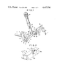
- FIG. 1 is a perspective view for a part of the upper feed dog mechanism in a first embodiment of this invention
- FIG. 2 is a perspective view for a part of the upper feed dog arm used in a second embodiment of this invention
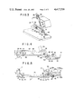
- FIGS. 3, 4 and 5 show a third embodiment of this invention, in which FIG. 3 is a schematic perspective view for the cloth presser part in an overlock type sewing machine, FIG. 4 is a side elevational view of the presser arm and FIG. 5 is a cross sectional view taken along line V--V in FIG. 4,
- FIG. 6 is a perspective view for a part of the upper feed member in a fourth embodiment of the invention.
- FIG. 7 is a perspective view for a part of the upper feed arm member in a fifth embodiment of this invention.
- FIG. 8 is a perspective view for a part of the upper feed member in a sixth embodiment of this invention.
- FIG. 1 shows a first embodiment, wherein a presser arm support member 1 is rotatably supported at one end by its shaft 2 to a machine frame and integrally formed at the other end with a vertical extension, the upper end of which is further extended horizontally into a support block 3.
- the presser arm support member 1 is movable in the counterclockwise direction by the manual operation of a worker, although the details thereof are not shown.
- the shaft 2 of the support member 1 is rotatably and loosely provided in the center of a rocking block 4, which is connected at the upper end to a link 5 which is a longitudinal driving member in the cloth feed mechanism of the sewing machine and which reciprocates horizontally interlocked with a horizontal feed shaft (not shown) for the control of horizontal feed and which rotatably supports at the lower end a horizontal stub shaft 8 perpendicular to the cloth feed direction.
- the horizontal shaft 8 is integrally formed with a connection block 7 having a horizontal forked end 6.
- the upper feed dog 10 is located at one end of the upper feed arm 9 whereas a flat portion 11 at its other end loosely engages the forked end 6 of the connection block 7 so that the upper feed arm 9 is rotatable in the clockwise direction around a vertical pin 12 as a vertical axis in FIG. 1.
- the presser shaft 13 is vertically movable through an adjustment screw 16 threaded into the machine frame of the sewing machine and is always biased downwardly by the resiliency of a spring 17 mounted within the adjustment screw 16.
- a knife arm 18 that supports a cloth cutting knife (not shown) at the top end is adapted to be rocked by its shaft 19 interlocked with the mechanism of the sewing machine such that it rotates clockwise while a needle (not shown) is being inserted into the cloth.
- a vertically movable arm 20, as the vertical driving member, is integrally formed with the knife arm 18 and extended rearwardly.
- a roller 21 supported at the top end of the arm 20 opposes the lower face on the top end of a leaf spring 22, whose base end is secured to the lower surface of the upper feed arm 9, and causes the upper feed arm 9 to rotate in the counterclockwise direction around the horizontal shaft 8 on the connection block 7 against the resilliency of the spring 17 when the knife arm 18 rotates in the clockwise direction.
- the link 5 moves rightwardly to rotate the rocking block 4 clockwise relative to the outer circumference of the shaft 2.
- the rocking movement causes the upper feed arm 9 to move leftwardly by way of the horizontal shaft 8, the connection block 7 and the pin 12, whereby the upper feed dog 10 moves in the cloth feed direction (indicated by the arrow in FIG. 1) while pressing the upper surface of the cloth by the resiliency of the spring 17 to feed the cloth.
- the horizontal shaft 8 of the connection block 7 rotates slightly relative to the lower end of the rocking block 4 in this case.
- the knife arm 18 rotates clockwise around the shaft 19 to move the roller 21 upwardly to thus raise the lower surface of the upper feed arm 9 by way of the leaf spring 22 against the resiliency of the spring 17, whereby the upper feed arm 9 rotates counterclockwise around the horizontal shaft 8 of the connected block 7 and the upper feed dog 10 rises from the upper surface of the cloth.
- the knife arm 18 rotates counterclockwise around the shaft 19 to lower the roller 21 and the upper feed arm 9 rotates clockwise around the horizontal shaft 8 of the connection block 7 under the resiliency of the spring 17 to lower the upper feed dog 10 so as to pressingly contact the upper surface of the cloth by the resiliency of the spring 17, whereby the initial state is resumed.
- the upper feed dog 10 conducts the four directional movement on or above the cloth for feeding it.
- the presser shaft 13 is raised either by loosening the adjust screw 16 or against the resiliency of the spring 17 to elevate the recess 14 at the lower end from above the upper end of the upper feed arm 9. Thereafter, the right hand portion of the upper feed arm 9 is pulled to this side in the drawing. Then, the upper feed arm 9 rotates in the clockwise direction around the pin 12 to move the upper feed dog 10 sideways away from the sewing area of the machine, wherein needle exchange or threading is conducted.
- FIG. 2 shows a part of the second embodiment of this invention, wherein the upper feed arm 9 is bisected into a fore arm portion 9a and a rear arm portion 9b.
- the rear arm portion 9b is connected at one end to the lower end of the rocking block 4 by means of a horizontal connecting shaft 23 perpendicular to the cloth feed direction; and the rear arm portion 9b and the fore arm portion 9a are rotatably connected to each other by means of a stepped screw as a vertical axis whose axial line is in a vertical direction so that the fore arm portion 9a is rotatable clockwise around the stepped screw 24.
- the upper feed dog (not shown) supported at the leading end of the fore arm portion 9a can also move in the four directions for feeding the cloth, as well as move sideways away from the sewing area for exchanging the needle or threading the needle in the same manner as in the first embodiment.
- FIGS. 3, 4 and 5 show the third embodiment of this invention, wherein a presser arm 25 is rotatably connected at its rear base end to the support block 3 of the presser arm support member 1 shown in FIG. 1 by means of a vertical pin 26 as a vertical axis.
- the presser arm support member 1 is rotatably supported by the integrally formed and horizontally extending shaft 2 to a machine frame 27, as stated above, and is manually rotatable by the worker in the counterclockwise direction in FIG. 4, while details thereof are not shown.
- the presser arm 25 supports at its top end, by means of a pin 32 having a horizontal axial line perpendicular to the cloth feed direction, a cloth presser foot 31 on which are formed needle passing apertures 28a and 28b, a thread guarding finger 29 and upper feed dog grooves 30a and 30b that open upstream of the needle passing aperture in the cloth feed direction.
- Presser member 33 contacts at the lower forked end the upper end of the presser arm 25, supported at the upper end vertically movably to the machine frame 27 and normally urges the leading end of the presser arm 25 downwardly by the resiliency of a compression spring 35 mounted between the lower end face of an adjust screw 34 threaded into the machine screw 27 and the presser member 33.
- a pressure release lever 36 is provided for manipulating the lower end of the presser member 33 between a pressing position in contact with the presser arm 25 and a non-pressing position elevated upwardly apart from the presser arm 25.
- An upper feed member 37 as a support member, is loosely engaged at the rear forked end 38 to the side of the presser arm 25 while putting a collar 39 between a rear washer 41 fixed by a screw 40 and the side face of the presser arm 25.
- the upper feed member 37 is formed at the front end with an idle hole 42 and supported by this portion to the side of the presser arm 25 movably both in the longitudinal direction (backward-to-forward direction) and vertical direction by means of a front washer 45 of a larger diameter fixed by a screw 44 by way of a collar 43 of a smaller diameter in the idle hole 42.
- An upper feed dog member 46 is fixed to the front end of the upper feed member 37 by a screw 47 so that its pair of feed dogs 10 correspond to the upper feed dog grooves 30a and 30b in the cloth presser foot 31 respectively.
- a cylinder 48 as one component of the connecting mechanism, is fixed at its base end to one end face of the upper feed member 37 by a screw 49 and formed at its leading end with an engaging aperture 50 which is perpendicular to the cloth feed direction and opens horizontally.
- Reference numeral 9 represents the leading end of the upper feed arm which is similar to that shown in FIG. 1 but not necessarily supported rotatably sideways, e.g., around the pin 12 in this case.
- the leading end of the upper feed arm 9 is normally projected under the downward resiliency near the sewing area and, interlocked with the mechanism of the sewing machine, moves in four directions with an opposite phase in the vertical movement to that of the vertical movement of the main and sub feed dogs.
- the leading end has an engaging block 52 formed with a spherical portion 51 as the other component of the connection mechanism that opposes to and engages the engaging aperture 50 in the cylinder 48.
- the engaging aperture 50 in the cylinder 48 as one component of the connection mechanism fixed to the upper feed member 37 and the spherical portion 51 of the engaging block 51 as the other component of the connection mechanism fixed to the upper feed arm 9 engage with each other in the state shown in FIGS. 3, 4 and 5.
- the needle moves vertically and the main and sub feed dogs opposing the cloth presser foot 31 also move in four directions to feed the cloth in cooperation with the presser foot in a well-known manner, while not shown.
- the upper feed arm 9 is interlocked with the mechanism of the sewing machine and the spherical portion 51 at the loading end also moves in four directions with the opposite phase in the vertical movement to that of the vertical movement of the main and sub feed dogs; that is, when the main and sub feed dogs rise the spherical portion 51 descends and, thereafter, moves in the cloth feed direction and, when the main and sub feed dogs descend, it rises and then moves in the direction opposite to the cloth feed direction.
- the four directional movement of the spherical portion 51 is transmitted by way of the engaging aperture 50 in the cylinder 48 to the upper feed member 37.
- the upper feed member 37 rotates clockwise at its rear fork end 38 around the collar 39 to press the cloth onto the upper surface of the throat plate by the lower end of the upper feed dog 10 at the leading end.
- the forked end of the upper feed member 37 slides at the collar 39 to feed the cloth by the upper feed dog 10.
- the forked end slides at the collar 39 to return the upper feed dog 10 to is beginning position.
- the upper feed dog 10 thus moves in four directions for feeding the cloth.
- the needle In order to exchange the needle, thread the needle or the like, the needle is moved to an elevated position and the pressure release lever 36 is manipulated to move the presser member 33 upwardly from the presser arm 25. Thereafter, when the leading end of the presser arm 25 or the upper feed member 37 is pushed sideways (or downwardly in FIG. 5), engagement between the spherical portion 51 and the engaging aperture 50 is released, whereby the presser arm 25 rotates around the pin 26 at the rear end and the upper feed member 37 having the upper feed dog 10 also rotates simultaneously with the presser arm 25 to move the cloth presser foot 31 and the upper feed dog 10 to positions separated from the sewing area.
- the work of exchanging the needle can be conducted with ease in this state.
- the presser arm 25 or the upper feed member 37 is rotated around the pin 26 in the direction opposed to that described above, the engaging aperture 50 in the cylinder 48 and the spherical portion 51 are aligned and engaged with each other and the pressure release lever 36 is manipulated to lower the presser member 33 to the upper surface of the presser arm 25, whereby the presser foot 31 and the upper feed dog 10 return to their beginning positions thereby enabling the cloth to be fed by the upper feed dog 10.
- FIG. 6 shows the fourth embodiment, wherein the forked end of the upper feed member 37 is made slidable to a square die 54 rotatably supported to a shaft 53 provided on the end face of the presser arm 25.
- FIG. 7 shows the fifth embodiment, wherein a shaft 58 provided to the rear end of the upper feed member 37 is connected slidably in the forward to backward direction to a pivotal member 56 whose shaft 55 is rotatable to the end face of the presser arm 25.
- FIG. 8 shows the sixth embodiment, wherein the upper or lower tip of the forked end is rotatably connected by way of a stepped screw 61 to one end of a vertical link 60 which is rotatably supported at the other end to the presser arm 25 by way of a stepped screw 50.
- the upper feed dog 10 is shown as situated at the upstream of the needle passing apertures in the cloth feed direction in each of the embodiments, the upper feed dog may, of course, be disposed at the downstream of the needle passing apertures in the cloth feed direction.
- the spherical portion 51 and the engaging aperture 50 in the cylinder 48 are employed as the connection mechanism between the leading end of the upper feed member 37 and the upper feed arm 9 in each of the foregoing embodiments, similar effects can be obtained by forming engaging apertures both in the upper feed member 37 and the leading end of the upper feed arm 9 and detachably mounting an engaging shaft to these engaging apertures.
- the upper feed arm 9 or the upper feed member 37 as the support member for supporting the cloth feed dog 10 is adapted to move in four directions on or above the upper surface of the cloth with a phase in the vertical movement opposite to that of the vertical movement of the lower feed dogs situated below the throat plate. It is designed to normally transmit the four directional movement to the upper feed dog 10 for feeding the cloth, as well as being made rotationally displaceable around a vertical axis in the direction for separating the upper feed dog sideways from the sewing area.
- the support member normally functions as the upper feed dog mechanism to the cloth and also improves operator efficiency by facilitating exchanging the needle, threading the needle or removing thread entangled in the sewing area and the looper due to thread disconnection.
Landscapes
- Engineering & Computer Science (AREA)
- Textile Engineering (AREA)
- Sewing Machines And Sewing (AREA)
Abstract
Description
Claims (4)
Applications Claiming Priority (2)
| Application Number | Priority Date | Filing Date | Title |
|---|---|---|---|
| JP55184830A JPS57107187A (en) | 1980-12-25 | 1980-12-25 | Upward feeding mechanism of sewing machine |
| JP55-184830 | 1980-12-25 |
Publications (1)
| Publication Number | Publication Date |
|---|---|
| US4417536A true US4417536A (en) | 1983-11-29 |
Family
ID=16160041
Family Applications (1)
| Application Number | Title | Priority Date | Filing Date |
|---|---|---|---|
| US06/333,317 Expired - Fee Related US4417536A (en) | 1980-12-25 | 1981-12-22 | Laterally pivotable upper feed dog |
Country Status (2)
| Country | Link |
|---|---|
| US (1) | US4417536A (en) |
| JP (1) | JPS57107187A (en) |
Cited By (5)
| Publication number | Priority date | Publication date | Assignee | Title |
|---|---|---|---|---|
| US4582010A (en) * | 1984-04-14 | 1986-04-15 | Union Special Gmbh | Upper feed mechanism for sewing machines |
| US4589364A (en) * | 1982-12-09 | 1986-05-20 | Pegasus Sewing Machine Mfg. Co. Ltd. | Sewing machine top feed |
| US5042406A (en) * | 1988-11-30 | 1991-08-27 | Mefina S.A. | Presser foot device for a sewing machine |
| US5174230A (en) * | 1990-07-17 | 1992-12-29 | Pegasus Sewing Machine Mfg. Co., Ltd. | Upper feed device for sewing machine |
| CN104073983A (en) * | 2013-03-27 | 2014-10-01 | 飞马缝纫机制造株式会社 | Vertical driving mechanism of upper feeding table of sewing machine |
Citations (3)
| Publication number | Priority date | Publication date | Assignee | Title |
|---|---|---|---|---|
| US3262410A (en) * | 1964-11-05 | 1966-07-26 | Michael Bork | Sewing machine work-feeding mechanism |
| US3530809A (en) * | 1969-03-17 | 1970-09-29 | Robert E Porter | Work feeder for sewing machine |
| US4285294A (en) * | 1979-07-04 | 1981-08-25 | Tokyo Juki Kogyo Kabushiki Kaisha | Upper layer feed mechanism in a sewing machine |
-
1980
- 1980-12-25 JP JP55184830A patent/JPS57107187A/en active Pending
-
1981
- 1981-12-22 US US06/333,317 patent/US4417536A/en not_active Expired - Fee Related
Patent Citations (3)
| Publication number | Priority date | Publication date | Assignee | Title |
|---|---|---|---|---|
| US3262410A (en) * | 1964-11-05 | 1966-07-26 | Michael Bork | Sewing machine work-feeding mechanism |
| US3530809A (en) * | 1969-03-17 | 1970-09-29 | Robert E Porter | Work feeder for sewing machine |
| US4285294A (en) * | 1979-07-04 | 1981-08-25 | Tokyo Juki Kogyo Kabushiki Kaisha | Upper layer feed mechanism in a sewing machine |
Cited By (6)
| Publication number | Priority date | Publication date | Assignee | Title |
|---|---|---|---|---|
| US4589364A (en) * | 1982-12-09 | 1986-05-20 | Pegasus Sewing Machine Mfg. Co. Ltd. | Sewing machine top feed |
| US4582010A (en) * | 1984-04-14 | 1986-04-15 | Union Special Gmbh | Upper feed mechanism for sewing machines |
| US5042406A (en) * | 1988-11-30 | 1991-08-27 | Mefina S.A. | Presser foot device for a sewing machine |
| US5174230A (en) * | 1990-07-17 | 1992-12-29 | Pegasus Sewing Machine Mfg. Co., Ltd. | Upper feed device for sewing machine |
| CN104073983A (en) * | 2013-03-27 | 2014-10-01 | 飞马缝纫机制造株式会社 | Vertical driving mechanism of upper feeding table of sewing machine |
| CN104073983B (en) * | 2013-03-27 | 2017-08-01 | 飞马缝纫机制造株式会社 | Lower drive mechanism on the upper feeding platform of sewing machine |
Also Published As
| Publication number | Publication date |
|---|---|
| JPS57107187A (en) | 1982-07-03 |
Similar Documents
| Publication | Publication Date | Title |
|---|---|---|
| US4417536A (en) | Laterally pivotable upper feed dog | |
| CN111020903A (en) | Seam-making thread trimming mechanism and method thereof | |
| JPS58112288U (en) | Upward feed device for sewing machine | |
| JPS5944072B2 (en) | Work piece trimming device for sewing machine | |
| JP5265217B2 (en) | Sewing machine lifting device | |
| JPS6234536Y2 (en) | ||
| US20050126459A1 (en) | Sewing machine with work edge cutting mechanism | |
| US4323020A (en) | Apparatus for overcoming sewing machine needle bind | |
| US5044290A (en) | Wiper unit of a sewing machine | |
| US3863580A (en) | Low-inertia presserfoot for sewing machines | |
| JPH04348795A (en) | Needle thread holder for sewing machine | |
| US6814018B1 (en) | Automatic thread cutting apparatus for sewing machines | |
| JPS6021754B2 (en) | Sewing machine presser foot device | |
| US7267063B2 (en) | Embroidery presser for embroidery machine | |
| US5046437A (en) | Device in a button sewing machine for maintaining looseness in needle thread while preventing the thread from being pulled out of the sewing needle | |
| JPH0232654Y2 (en) | ||
| US4724783A (en) | A sewing machine with a synchronizing feed device | |
| CN113969470A (en) | Novel embroidery sheet tucking and sheet feeding mechanism thereof | |
| JPH0126718B2 (en) | ||
| US20030209177A1 (en) | Fabric guide device for a sewing machine | |
| US4221181A (en) | Throat plate for above the bed feed system | |
| US4216734A (en) | Sewing machine with universal upper feed | |
| US4582010A (en) | Upper feed mechanism for sewing machines | |
| CN220224573U (en) | Sewing machine capable of achieving thread cutting and presser foot lifting functions through single driving source | |
| DE3150806C2 (en) | Knife slide device for sewing machines |
Legal Events
| Date | Code | Title | Description |
|---|---|---|---|
| AS | Assignment |
Owner name: TOKYO JUKI INDUSTRIAL CO. LTD., 2-1, KOKURYOMACHI Free format text: ASSIGNMENT OF ASSIGNORS INTEREST.;ASSIGNOR:SHIOMI, KENGO;REEL/FRAME:003970/0522 Effective date: 19811209 |
|
| FEPP | Fee payment procedure |
Free format text: PAYOR NUMBER ASSIGNED (ORIGINAL EVENT CODE: ASPN); ENTITY STATUS OF PATENT OWNER: LARGE ENTITY |
|
| MAFP | Maintenance fee payment |
Free format text: PAYMENT OF MAINTENANCE FEE, 4TH YEAR, PL 96-517 (ORIGINAL EVENT CODE: M170); ENTITY STATUS OF PATENT OWNER: LARGE ENTITY Year of fee payment: 4 |
|
| MAFP | Maintenance fee payment |
Free format text: PAYMENT OF MAINTENANCE FEE, 8TH YEAR, PL 96-517 (ORIGINAL EVENT CODE: M171); ENTITY STATUS OF PATENT OWNER: LARGE ENTITY Year of fee payment: 8 |
|
| FEPP | Fee payment procedure |
Free format text: MAINTENANCE FEE REMINDER MAILED (ORIGINAL EVENT CODE: REM.); ENTITY STATUS OF PATENT OWNER: LARGE ENTITY |
|
| LAPS | Lapse for failure to pay maintenance fees | ||
| FP | Lapsed due to failure to pay maintenance fee |
Effective date: 19951129 |
|
| STCH | Information on status: patent discontinuation |
Free format text: PATENT EXPIRED DUE TO NONPAYMENT OF MAINTENANCE FEES UNDER 37 CFR 1.362 |