US4416035A - Safety bar cutoff and brake - Google Patents
Safety bar cutoff and brake Download PDFInfo
- Publication number
- US4416035A US4416035A US06/310,109 US31010981A US4416035A US 4416035 A US4416035 A US 4416035A US 31010981 A US31010981 A US 31010981A US 4416035 A US4416035 A US 4416035A
- Authority
- US
- United States
- Prior art keywords
- frame
- trip plate
- brake
- trip
- actuator
- Prior art date
- Legal status (The legal status is an assumption and is not a legal conclusion. Google has not performed a legal analysis and makes no representation as to the accuracy of the status listed.)
- Expired - Lifetime
Links
Images

Classifications
-
- D—TEXTILES; PAPER
- D01—NATURAL OR MAN-MADE THREADS OR FIBRES; SPINNING
- D01G—PRELIMINARY TREATMENT OF FIBRES, e.g. FOR SPINNING
- D01G31/00—Warning or safety devices, e.g. automatic fault detectors, stop motions
-
- Y—GENERAL TAGGING OF NEW TECHNOLOGICAL DEVELOPMENTS; GENERAL TAGGING OF CROSS-SECTIONAL TECHNOLOGIES SPANNING OVER SEVERAL SECTIONS OF THE IPC; TECHNICAL SUBJECTS COVERED BY FORMER USPC CROSS-REFERENCE ART COLLECTIONS [XRACs] AND DIGESTS
- Y10—TECHNICAL SUBJECTS COVERED BY FORMER USPC
- Y10T—TECHNICAL SUBJECTS COVERED BY FORMER US CLASSIFICATION
- Y10T74/00—Machine element or mechanism
- Y10T74/21—Elements
- Y10T74/2193—Guard mechanisms
Definitions
- This invention relates to lint cleaners and more particularly to an emergency safety bar and brake for a lint cleaner.
- Lint cleaners are well-known machines for cotton gins. For example, see JAMES L. HORN'S U.S. Pat. No. 3,877,111 for a lint cleaner.
- these machines will have a large diameter condenser drum upon which lint cotton in an air stream is impinged.
- a batt is formed upon the drum which is doffed by doffing rollers. From the doffing rollers, the batt is fed through directional rollers to a saw cylinder where the cleaning process occurs.
- Interviews with persons who have been caught in this type machinery say that normally the placement of the safety bar is not critical inasmuch as people, caught in machinery will be pushing against everything on the front of the machine trying to pull away from it. This is an instinctive action and not a pre-planned action.
- my invention does two things: (1) immediately cuts the power to the motor driving the rolls, and (2) applies a brake to transmission elements which transmit the power from the motor to the feed rolls, inasmuch as there is considerable momentum to the moving elements. Therefore, it is possible to stop the machine before serious injury is done to the workman.
- the total function of the safety stop and brake far exceeds the sum of the function of the individual elements such as springs, pitmans, levers, etc.
- An object of this invention is to prevent injuries to workmen.
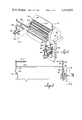
- FIG. 1 is a perspective view of my invention mounted upon a lint cleaner with only a portion of the lint cleaner shown.
- FIG. 2 is a front elevational view thereof.
- FIG. 3 is a side elevational view thereof.
- FIG. 4 is a side elevational view of a portion thereof, showing details of construction.
- FIG. 5 is a section view taken substantially on line 5--5 showing details of construction.
- the lint cleaner has frame 12 having two sides.
- the frame supports the various bearings which in turn supports feed rollers 14 as well as doffing roller 16.
- Also supported by the frame is the saw cylinder which is not shown in the drawing.
- the feed roller 14, doffing roller 16, and saw cylinder are all journaled by bearings for rotation.
- the cylinders or rollers extend from one side of the frame to the other with each roller being journaled to a bearing mounted on one side of the frame and journaled in another bearing mounted on the other side of the frame.
- the lint cleaner 10 would be found in a cotton gin. However, it is of the general category of textile equipment. Textile mills have equipment having feed rollers quite similar to feed rollers 14.
- Housing 18 covers the rotating rollers within the machine. Opening 20 in the housing 18 is adjacent to the feed rollers 14 and doffing roller 16. Access door 22 partially covers the opening 20, when closed.
- Electric motor 24 is mounted upon the frame 12 at one end. It is connected by transmission means 26 to the rollers for revolving the rollers.
- actuator arm 30 is pivoted to the frame 12 on each side of the frame.
- At least one actuator bar 32 extends from the actuator arm 30 on one side of the machine to the actuator arm 30 on the other side of the machine.
- two actuator bars are used, however, according to the particular design, either one bar could be used particularly if it were much wider than the circular bar as shown.
- the bars are shown in front of the opening 20. However, as discussed above, it is not necessary that they be directly in front of the opening 20, but merely at the opening.
- Trip plate 34 is pivoted to the one side of the frame 12. As a detail of construction, the trip plate 34 is pivoted by shaft 76 to mounting plate 29 which depends from angle member 28. The axis of the pivot (shaft 76) of the trip plate 34 is parallel to the axis of the pivot 44 of the arms 30. The trip plate 34 will have two positions. One being a run position and the other being a stop position. Helical tension trip spring 36 is attached between the trip plate 34 and frame 12. The trip spring 36 biases the trip plate 34 to the stop position.
- One of the actuator arms 30 extends downward to adjacent the trip plate 34 and has sear 38 thereon.
- the sear 38 fits within notch 40 upon the trip plate 34 when the trip plate is in the run position.
- Helical tension actuator spring 42 is attached between the actuator arm 30 and the frame 12. It holds or biases the sear 38 into the notch 40.
- the pivot point 44 of the actuator arm 30 is between the actuator bar 32 and the sear 38.
- the pivot point 44 is between the arm 30 and angle member 28 which is attached, as by welding, to frame 12.
- the sear 38 is outboard of the trip plate 34 and that the actuator bars 32 are outboard of the opening 20.
- Electric switch 50 having switch arm 52 thereon is attached to the frame 12 adjacent to the trip plate 34.
- switch flange 54 upon the trip plate bears against the switch arm 52 which maintains the switch in run position.
- the switch 50 is connected by electric wires 55 to the electric motor 24 so that if the switch arm 52 is not depressed by the trip plate 34 through the flange 54 the motor is in an inoperative condition and will be stopped. I.e., when the trip plate 34 rotates to the stop position, the electric motor 24 will be stopped.
- a brake assembly including a caliper-type disc brake 56 is mounted upon the frame 12. As seen in the drawing, the actuator arms 30 and the trip plate 34 are pivoted to the frame 12 near the front of the frame while the disc brake 56 is located near the rear of the frame.
- the disc brake 56 acts upon disc 58 which is attached to one of the rotatable portions of the transmission means 26 whereby the rollers 14 and 16 are rotated.
- the disc brake 56 includes brake arm 60 which actuates the brake. As seen in the drawing, when the brake arm 60 is rotated clockwise, it will apply the brake.
- Brake pitman 62 extends from the brake arm 60 to depending rocker arm 64 upon rocker shaft 66. Brake pitman 62, arm 64 and rocker shaft 66 are all portions of the brake assembly as is upright rocker arm 68.
- Helical tension brake spring 70 extends from the depending rocker arm 64 to the frame 12. As may be seen in the drawing the brake spring 70 will bias the brake to the brake position. I.e., unless the depending rocker arm 64 is not held in the run position, the brake spring 70 will pull the brake pitman 62 so as to rotate the brake arm 60 in a clockwise direction, thus applying the disc brake 56 to the transmission means 26.
- trip pitman 72 extending from the trip plate 34 to the upright arm 68 will hold the rocker arm 64 and 68 in the run position.
- the reset lever 46 is not attached directly to the trip plate 34 but is attached to a to shaft 74 extending outward from the trip plate.
- the shaft 74 is mounted above trip plate pivot shaft 76.
- the trip pitman 72 is attached to ear 78 also mounted on this reset lever shaft 74.
- the depending arm 64 and upright arm 68 are not in the same plane but are spaced from one another along the rocker shaft 66 as to properly space these pitmans for proper actuation.
- this unit is adapted to be added to existing units.
- the trip plate assembly is attached to one side of the machine.
- the rocker shaft 66 together with the disc brake 56 and the disc 58 are readily attached to existing machines.
- the actuator arms 30 are pivoted on each side of the machine by the actuator pivot point or pivot shaft 44 on angle member 28. Difficulty has been experienced in some cases in getting the actuator pivot shafts 44 precisely aligned so that the actuator arms 30 rotate smoothly and freely. It has been found that if a hinge is placed in the actuator arm above the actuator pivot point, or pivot shaft 44 and below the actuator bar 32 that it works more freely.
- the actuator bar on one side has two parts: a lower part 80 having ears 82 welded thereto, and an upper actuator arm 84 having shaft 86 welded thereto. Therefore, by having this articulation in the arm, it is found that the arms pivot upon their pivot shafts 44 more freely, even if the angle 28 are not exactly aligned by highly skilled craftsmen.
Landscapes
- Engineering & Computer Science (AREA)
- Textile Engineering (AREA)
- Preliminary Treatment Of Fibers (AREA)
Abstract
Description
______________________________________ 10 lint cleaner 50electric switch 12frame 52 switch arm 14feed roller 54switch flange 16 doffing roller 55electric wires 18housing 56disc brake 20opening 58disc 22 access door 60brake arm 24electric motor 62brake pitman 26 transmission means 64 dependingrocker arm 28angle member 66rocker shaft 29 mountingplate 68upright rocker arm 30actuator arm 70brake spring 32actuator bar 72trip pitman 34trip plate 74 shaft, resetlever 36trip spring 76 tripplate pivot shaft 38 sear 78 ear 40notch 80lower actuator arm 42actuator spring 82ears 44actuator pivot point 84upper actuator arm 46reset lever 86shaft 48 reset finger ______________________________________
Claims (10)
Priority Applications (2)
| Application Number | Priority Date | Filing Date | Title |
|---|---|---|---|
| US06/310,109 US4416035A (en) | 1981-10-09 | 1981-10-09 | Safety bar cutoff and brake |
| US06/495,675 US4454631A (en) | 1981-10-09 | 1983-05-18 | Improved safety bar cutoff and brake method |
Applications Claiming Priority (1)
| Application Number | Priority Date | Filing Date | Title |
|---|---|---|---|
| US06/310,109 US4416035A (en) | 1981-10-09 | 1981-10-09 | Safety bar cutoff and brake |
Related Child Applications (1)
| Application Number | Title | Priority Date | Filing Date |
|---|---|---|---|
| US06/495,675 Division US4454631A (en) | 1981-10-09 | 1983-05-18 | Improved safety bar cutoff and brake method |
Publications (1)
| Publication Number | Publication Date |
|---|---|
| US4416035A true US4416035A (en) | 1983-11-22 |
Family
ID=23201020
Family Applications (1)
| Application Number | Title | Priority Date | Filing Date |
|---|---|---|---|
| US06/310,109 Expired - Lifetime US4416035A (en) | 1981-10-09 | 1981-10-09 | Safety bar cutoff and brake |
Country Status (1)
| Country | Link |
|---|---|
| US (1) | US4416035A (en) |
Cited By (3)
| Publication number | Priority date | Publication date | Assignee | Title |
|---|---|---|---|---|
| WO1990012131A1 (en) * | 1989-04-13 | 1990-10-18 | Hergeth Hollingsworth Gmbh | Device for cleaning textile fibres |
| US5131515A (en) * | 1991-04-19 | 1992-07-21 | Westlake Farms, Inc. | Safety apparatus closure lock controlling access to rotational member |
| US5538490A (en) * | 1993-02-15 | 1996-07-23 | Fujitsu Limited | Safety bar mechanism and sheet processing device having a safety bar mechanism |
Citations (4)
| Publication number | Priority date | Publication date | Assignee | Title |
|---|---|---|---|---|
| US3498217A (en) * | 1967-03-11 | 1970-03-03 | Heidelberger Druckmasch Ag | Safety device for machines having oppositely rotating cylinders |
| US3877111A (en) * | 1973-05-23 | 1975-04-15 | Horn & Gladden | Lint cleaner |
| US4041765A (en) * | 1976-08-26 | 1977-08-16 | Kemper Morton L | Press brake guard |
| US4282963A (en) * | 1979-05-03 | 1981-08-11 | Hammermill Paper Company | Barrier guard |
-
1981
- 1981-10-09 US US06/310,109 patent/US4416035A/en not_active Expired - Lifetime
Patent Citations (4)
| Publication number | Priority date | Publication date | Assignee | Title |
|---|---|---|---|---|
| US3498217A (en) * | 1967-03-11 | 1970-03-03 | Heidelberger Druckmasch Ag | Safety device for machines having oppositely rotating cylinders |
| US3877111A (en) * | 1973-05-23 | 1975-04-15 | Horn & Gladden | Lint cleaner |
| US4041765A (en) * | 1976-08-26 | 1977-08-16 | Kemper Morton L | Press brake guard |
| US4282963A (en) * | 1979-05-03 | 1981-08-11 | Hammermill Paper Company | Barrier guard |
Cited By (3)
| Publication number | Priority date | Publication date | Assignee | Title |
|---|---|---|---|---|
| WO1990012131A1 (en) * | 1989-04-13 | 1990-10-18 | Hergeth Hollingsworth Gmbh | Device for cleaning textile fibres |
| US5131515A (en) * | 1991-04-19 | 1992-07-21 | Westlake Farms, Inc. | Safety apparatus closure lock controlling access to rotational member |
| US5538490A (en) * | 1993-02-15 | 1996-07-23 | Fujitsu Limited | Safety bar mechanism and sheet processing device having a safety bar mechanism |
Similar Documents
| Publication | Publication Date | Title |
|---|---|---|
| US4378637A (en) | Hedge cutting arrangement | |
| DE2200686C3 (en) | Open-end spinning machine | |
| US4416035A (en) | Safety bar cutoff and brake | |
| US7331111B2 (en) | Chainsaw throttle and brake mechanisms | |
| US4454631A (en) | Improved safety bar cutoff and brake method | |
| DE19650597A1 (en) | Open end spinner fibre loosening roller assembly | |
| US2889855A (en) | Loom driving mechanism | |
| US5131515A (en) | Safety apparatus closure lock controlling access to rotational member | |
| US3984896A (en) | Safety device for lint cleaners | |
| US20060174439A1 (en) | Power nozzle for a floor cleaning apparatus | |
| CA1153326A (en) | Infeed knob normally disengaged from power shaft | |
| US4022220A (en) | Cutter head for a machine for picking sprouts | |
| US2648875A (en) | Clearer tensioning device | |
| SE507298C2 (en) | fly fishing reel | |
| US580874A (en) | Safety device for cutting-machines | |
| US239839A (en) | Roving-delivery mechanism for drawing-frames | |
| EP3647005B1 (en) | Trunk sawing machine | |
| US74874A (en) | Improvement in steippees foe oaeding-oylindees | |
| US833067A (en) | Automatic safety-brake for tread-powers. | |
| CN213414318U (en) | Flexible mounting structure of pre-feeding mechanism | |
| US209001A (en) | Improvement in leather-splitting machines | |
| JPH09225829A (en) | Ground material control device for belt grinder | |
| US779123A (en) | Thread-dressing machine. | |
| JPS595865Y2 (en) | paper conveyance device | |
| US771229A (en) | Tension device for grain-binders. |
Legal Events
| Date | Code | Title | Description |
|---|---|---|---|
| AS | Assignment |
Owner name: HORN AND GLADDEN LINT CLEANER COMPANY INC P O BOX Free format text: ASSIGNMENT OF ASSIGNORS INTEREST.;ASSIGNOR:SCHWARTZ, ROBERT C.;REEL/FRAME:003937/0551 Effective date: 19811006 |
|
| STCF | Information on status: patent grant |
Free format text: PATENTED CASE |
|
| MAFP | Maintenance fee payment |
Free format text: PAYMENT OF MAINTENANCE FEE, 4TH YEAR, PL 96-517 (ORIGINAL EVENT CODE: M170); ENTITY STATUS OF PATENT OWNER: SMALL ENTITY Year of fee payment: 4 |
|
| AS | Assignment |
Owner name: CONSOLIDATED HGM CORPORATION, P.O. BOX 2159, LUBBO Free format text: ASSIGNMENT OF ASSIGNORS INTEREST.;ASSIGNOR:HORN, JAMES L.;REEL/FRAME:004730/0324 Effective date: 19870506 Owner name: CONSOLIDATED HGM CORPORATION, A TX CORP,TEXAS Free format text: ASSIGNMENT OF ASSIGNORS INTEREST;ASSIGNOR:HORN, JAMES L.;REEL/FRAME:004730/0324 Effective date: 19870506 |
|
| AS | Assignment |
Owner name: HORN, JAMES L., 8602 VICKSBURG, LUBBOCK, TEXAS 794 Free format text: ASSIGNMENT OF ASSIGNORS INTEREST.;ASSIGNOR:HORN & GLADDEN LINT CLEANER COMPANY, INC. A/K/A HORN & GLADDEN LINT CLEANER, INC. HORN & GLADDEN, INC.;REEL/FRAME:004678/0934 Effective date: 19870312 |
|
| AS | Assignment |
Owner name: FIRST NATIONAL BANK AT LUBBOCK, TEXAS Free format text: SECURITY INTEREST;ASSIGNOR:CONSOLIDATED HGM CORP; A/K/A CONSOLIDATED HGM;REEL/FRAME:005358/0916 Effective date: 19900308 |
|
| FEPP | Fee payment procedure |
Free format text: PAYMENT IS IN EXCESS OF AMOUNT REQUIRED. REFUND SCHEDULED (ORIGINAL EVENT CODE: F169); ENTITY STATUS OF PATENT OWNER: SMALL ENTITY |
|
| MAFP | Maintenance fee payment |
Free format text: PAYMENT OF MAINTENANCE FEE, 8TH YEAR, PL 96-517 (ORIGINAL EVENT CODE: M171); ENTITY STATUS OF PATENT OWNER: SMALL ENTITY Year of fee payment: 8 |
|
| AS | Assignment |
Owner name: CONSOLIDATED COTTON GIN CO., INC. A TX CORPORATI Free format text: ASSIGNMENT OF ASSIGNORS INTEREST.;ASSIGNOR:CONSOLIDATED HGM CORPORATION, A CORPORATION OF TX;REEL/FRAME:005916/0250 Effective date: 19911107 |
|
| AS | Assignment |
Owner name: PALINS NATIONAL BANK, THE, TEXAS Free format text: SECURITY AGREEMENT TRANSFERRING FROM FIRST NATIONAL BANK AT LUBBOCK TO THE PLAINS NATIONAL BANK OF LUBBOCK;ASSIGNOR:CONSOLIDATED COTTON GIN CO., INC.;REEL/FRAME:006979/0505 Effective date: 19940311 |
|
| MAFP | Maintenance fee payment |
Free format text: PAYMENT OF MAINTENANCE FEE, 12TH YR, SMALL ENTITY (ORIGINAL EVENT CODE: M285); ENTITY STATUS OF PATENT OWNER: SMALL ENTITY Year of fee payment: 12 |
|
| AS | Assignment |
Owner name: BRADFORD L. MOORE TRUSTEE, TEXAS Free format text: ASSIGNMENT OF SECURITY AGREEMENT;ASSIGNOR:KENT COUNTY STATE BANK;REEL/FRAME:016914/0290 Effective date: 20050331 |