US4411447A - Vehicle suspension system - Google Patents
Vehicle suspension system Download PDFInfo
- Publication number
- US4411447A US4411447A US06/317,709 US31770981A US4411447A US 4411447 A US4411447 A US 4411447A US 31770981 A US31770981 A US 31770981A US 4411447 A US4411447 A US 4411447A
- Authority
- US
- United States
- Prior art keywords
- cylinder
- piston
- accumulator
- main
- auxiliary
- Prior art date
- Legal status (The legal status is an assumption and is not a legal conclusion. Google has not performed a legal analysis and makes no representation as to the accuracy of the status listed.)
- Expired - Fee Related
Links
Images
Classifications
-
- B—PERFORMING OPERATIONS; TRANSPORTING
- B60—VEHICLES IN GENERAL
- B60G—VEHICLE SUSPENSION ARRANGEMENTS
- B60G11/00—Resilient suspensions characterised by arrangement, location or kind of springs
- B60G11/26—Resilient suspensions characterised by arrangement, location or kind of springs having fluid springs only, e.g. hydropneumatic springs
- B60G11/30—Resilient suspensions characterised by arrangement, location or kind of springs having fluid springs only, e.g. hydropneumatic springs having pressure fluid accumulator therefor, e.g. accumulator arranged in vehicle frame
-
- B—PERFORMING OPERATIONS; TRANSPORTING
- B60—VEHICLES IN GENERAL
- B60G—VEHICLE SUSPENSION ARRANGEMENTS
- B60G21/00—Interconnection systems for two or more resiliently-suspended wheels, e.g. for stabilising a vehicle body with respect to acceleration, deceleration or centrifugal forces
- B60G21/02—Interconnection systems for two or more resiliently-suspended wheels, e.g. for stabilising a vehicle body with respect to acceleration, deceleration or centrifugal forces permanently interconnected
- B60G21/06—Interconnection systems for two or more resiliently-suspended wheels, e.g. for stabilising a vehicle body with respect to acceleration, deceleration or centrifugal forces permanently interconnected fluid
Definitions
- This invention relates to vehicles and in particular to hydraulic strut suspension systems for use in vehicles.
- off-highway vehicles have relatively high centers of gravity.
- such vehicles tend to roll in a turn or on a side slope.
- they transfer greater loads to the outboard strut, causing the strut to contract and thus further aggravate the problem.
- the present problem is directed to overcoming one or more of the problems set forth.
- the present invention comprehends an improved vehicle suspension which is relatively soft in the bounce mode and relatively stiff in the roll mode.
- the disclosed system utilizes a plurality of accumulators having different spring constants in a novel manner to provide the desired suspension control.
- the arrangement is extremely simple and economical of construction while yet providing the improved suspension characteristics.
- an accumulator means having either a dual piston or a pair of interconnected pistons.
- a pair of smaller accumulators are interconnected with the main accumulator to the head end of the struts which are connected between the frame and axle of the vehicle on opposite sides thereof.
- the auxiliary, smaller accumulators have a relatively high spring constant and are connected so as to provide high stiffness in the roll mode while being effectively inactive in the bounce mode.
- the main accumulator In the bounce mode, the main accumulator provides a relatively soft suspension.
- the accumulators are provided with resilient movement resisting means and, more specifically in the illustrated embodiment, are provided with gas chambers permitting the enclosed gas therein to serve as a resilient spring means.
- the difference in stiffness between the auxiliary accumulators and that of the main accumulator may be effected by providing the gas in the auxiliary accumulators at a relatively higher precharged pressure and/or the value of the gas in the auxiliary accumulators at a precharged volume smaller than that of the main accumulator.
- the invention is advantageously adapted for use in a vehicle having a frame provided with wheels carried on left and right portions of the rear axle.
- a left suspension strut having a hydraulic cylinder is provided with a movable piston, and one of these elements is fixedly associated with the axle left portion, the other of the elements being fixedly associated with the frame left portion.
- a right suspension strut having a hydraulic cylinder is provided with a movable piston.
- One of the right strut cylinder and piston means is fixedly associated with the axle right portion, and the other of these right strut elements is fixedly associated with the frame right portion. The struts cooperatively suspend the frame on the axle.
- the invention includes improved means for controlling the movement of the strut pistons, including a main pressure accumulator structure having at least one pressure accumulator provided with first and second pistons defining respectively equal area first and second pressure surfaces, cylinders movably housing the pistons, and means for causing joint movement of the pistons in the cylinders.
- the accumulators further include elements for resisting the joint movement of the pistons, a left auxiliary pressure accumulator having a third piston and cylinder movably housing the third piston, and second resilient element for resisting movement of the third piston.
- the invention further includes a right auxiliary pressure accumulator having a fourth piston and cylinder movably housing the fourth piston, and third resilient element for resisting movement of the fourth piston.
- the structure further includes means hydraulically connecting the left strut cylinder with the main and left auxiliary accumulator cylinders to direct fluid pressure from the left strut cylinder against the first and third pistons.
- the structure still further includes means hydraulically connecting the right strut cylinder with the main and right auxiliary accumulator cylinders to direct fluid pressure from the right strut cylinder against the second and fourth pistons, the spring rate of the second and third resilient elements being greater than the spring rate of the first resilient element to provide a first suspension stiffness as an incident of a bounce of the wheels and a second, greater suspension stiffness as an incident of a tilt roll of the wheeled axle.
- the piston means of the main pressure accumulator means comprises a single piston having a pair of pressure surfaces.
- the main pressure accumulator comprises a pair of cylinders each having an associated piston, with the pistons being mechanically interconnected for joint movement thereof.
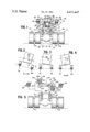
- FIG. 1 is a schematic elevation illustrating the arrangement of a preferred form of vehicle suspension system showing the embodiment of the present invention
- FIG. 2 is a force diagram illustrating the arrangement of forces acting on the system when the vehicle is disposed on a slope
- FIG. 3 is a force diagram illustrating the arrangement of the forces during lefthand cornering of the vehicle
- FIG. 4 is a force diagram illustrating the arrangements during a righthand cornering of the vehicle.
- FIG. 5 is a schematic elevation illustrating a modified form of vehicle suspension system showing another embodiment of the present invention.
- a vehicle generally designated 10 is provided with a frame 11 having a left portion 12 and a right portion 13.
- a pair of left wheels 14 is carried on a left portion 15 of an axle 16, and a pair of right wheels 17 is carried on a right portion 18 of the axle.
- a left suspension strut generally designated 19 is connected between left portion 15 of the axle and left portion 12 of the frame.
- a right suspension strut generally designated 20 is connected between the right portion 18 of axle 16 and right portion 13 of the frame 11.
- Left suspension strut 19 defines a fluid cylinder 21 in which is movably mounted a fluid piston 22.
- Right suspension strut 20 defines a cylinder 23 in which is movably mounted a piston 24.
- a conduit 25 is connected to the head end of cylinder 21 and is provided with a damping orifice 26.
- a conduit 27 is connected to the head end of cylinder 23 and is provided with a damping orifice 28.
- Conduit 25 is provided with branch conduits 29 leading to a first auxiliary accumulator 30, and branch conduit 31 leading to a main accumulator 32.
- Conduit 27 is provided with a first branch conduit 33 leading to the main accumulator 32, and a second branch conduit 34 leading to a second auxiliary accumulator 35.
- Accumulator 30 includes a closed cylinder 36 enclosing a movable piston 37.
- Branch conduit 29 communicates with the lower end of the cylinder below piston 37 and the head end of the cylinder, above piston 37, is filled with a compressible fluid, such as gas 38.
- Auxiliary accumulator 35 similarly is defined by a closed cylinder 39 and a movable piston 40 therein.
- Branch conduit 34 communicates with the lower end of cylinder 39 below piston 40 and the head end of the cylinder is filled with a compressible fluid, such as gas 41.
- the main accumulator is defined by a stepped cylinder 42 having a large diameter end portion 43 and a small diameter end portion 44.
- a piston means 45 is movably disposed in the cylinder and includes a first piston 46 received in the large diameter portion 43 of the cylinder, and a small piston 47 received in the small diameter portion 44 of the cylinder.
- Branch line 33 of conduit 27 communicates with the lower end of cylinder portion 44 below piston 47 and branch line 31 of conduit 25 communicates with the portion of the cylinder below the upper piston 46.
- a resiliently compressible fluid, such as gas 48, is provided in the head end of the cylinder above piston 45.
- a modified form of suspension control system is shown to comprise a system generally similar to that of FIG. 1 but wherein the main accumulator means generally designated 132 is defined by a pair of separate piston-cylinder devices generally designated 149 and 150.
- Device 149 includes a cylinder 151 in which is movably received a piston 152 and device 150 is defined by a cylinder 153 in which is movably received a piston 154.
- Piston 152 is provided with a piston rod 155 which is connected to one end 156 of a pivotal rocker arm 157 and piston 154 is provided with a piston rod 158 connected to the opposite end 159 of the rocker arm 157.
- the pistons are mechanically interconnected for joint movement.
- the branch line 131 is connected to the cylinder 151 below the piston 152 and a resilient fluid in the form of a gas 160 is provided in the head end of cylinder 151 above piston 152.
- Branch conduit 133 is connected to the upper end of cylinder 153 above the piston 154 and the lower end of the cylinder is provided with a resilient fluid, such as gas 161.
- the area of surface 62 of piston 46 is preferably equal to the area of lower surface 63 of lower piston 47 in main accumulator 32.
- the areas of pistons 152 and 154 in accumulator devices 149 and 150 are preferably equal.
- the accumulator devices 149 and 150 function substantially similarly to accumulator means 32.
- the vehicle suspension system of the present invention functions in a novel and simple manner. More specifically, when the vehicle bounces, hydraulic fluid is forced from each of the struts through the conduits 25 and 28 to the main accumulator 32. As the fluid delivered to the main accumulator is equally delivered to the surfaces 62 and 63, which as discussed above are of equal area, the hydraulic pressure acts equally on the piston 45 so as to compress the gas 48 which thus acts as a spring and shock absorber.
- the volume of gas 48 in cylinder portion 43 may be relatively large and the precharged pressure thereof may be relatively low so as to provide a relatively low spring constant in the soft bounce of the vehicle.
- the axle 16 may move up and down parallel with the truck frame 11.
- a force such as force FR acting on the right wheels
- the upward force FL acting on the left wheels such as due to a bump in the road engaged by the right wheels only, a pothole in the road under the left wheels only, etc.
- the force is directed through the struts tending to cause the frame to roll correspondingly.
- the spring rate of the auxiliary accumulators 30 and 35 is made to be greater than the spring rate of the main accumulator 32.
- the precharge of the gas 38 and 41 may be set higher than the precharge of gas 48 in the main accumulator.
- the total volume of the gas 38 in accumulator 30 and gas 41 in accumulator 35 may be made smaller than the total volume of gas 48 in accumulator 32.
- the auxiliary accumulators are stiffer than the main accumulator and, thus, the system provides a greater stiffness relative to a rolling movement of the frame than to the bouncing movement thereof, as described above.
- the main accumulator 32 acts as a relatively soft spring suspension for the vehicle in the bounce mode and the auxiliary accumulators 30 and 35 act as relatively stiff suspensions of the frame in the roll mode. This action is provided notwithstanding the relatively close spacing of the struts 19 and 20, as shown in FIG. 1, as may be necessitated by the use of the dual wheels on each end of the axle.
- the stiffness of the bounce controlling main accumulator 32 may be set for any value relative to the stiffness of the roll control auxiliary accumulators 30 and 35, the system is advantageously adapted for use with a wide range of vehicles, such as tractors and the like.
- the system may be utilized with either the front or rear wheels of the vehicle. As illustrated in FIG. 2, the system functions similarly where the vehicle is riding in an inclined manner on a slope S, and as shown in FIGS. 3 and 4, the system functions to control the roll in right and left cornering of the vehicle.
- the system functions substantially identically to the system of FIG. 1 except for the modified arrangement of the pistons of the accumulator devices 149 and 150 which move in opposite directions rather than in the same direction as a result of the rocker arm-type connection therebetween.
- the areas of the pistons are equal so that hydraulic liquid delivered to the piston chambers causes movement of the respective pistons in the same manner as in accumulator 32.
- any method of interconnecting the pistons of the main accumulator means may be utilized within the scope of the invention.
- the improved suspension control permits the struts to be maintained relatively small while yet disposed in relatively close spacing.
- the invention is advantageously adapted for use with vehicles as shown in FIG. 1, wherein only a small amount of free space is available between the vehicle wheels.
Abstract
Description
Claims (14)
Priority Applications (1)
| Application Number | Priority Date | Filing Date | Title |
|---|---|---|---|
| US06/317,709 US4411447A (en) | 1981-11-02 | 1981-11-02 | Vehicle suspension system |
Applications Claiming Priority (1)
| Application Number | Priority Date | Filing Date | Title |
|---|---|---|---|
| US06/317,709 US4411447A (en) | 1981-11-02 | 1981-11-02 | Vehicle suspension system |
Publications (1)
| Publication Number | Publication Date |
|---|---|
| US4411447A true US4411447A (en) | 1983-10-25 |
Family
ID=23234928
Family Applications (1)
| Application Number | Title | Priority Date | Filing Date |
|---|---|---|---|
| US06/317,709 Expired - Fee Related US4411447A (en) | 1981-11-02 | 1981-11-02 | Vehicle suspension system |
Country Status (1)
| Country | Link |
|---|---|
| US (1) | US4411447A (en) |
Cited By (8)
| Publication number | Priority date | Publication date | Assignee | Title |
|---|---|---|---|---|
| FR2576850A1 (en) * | 1985-02-07 | 1986-08-08 | Peugeot | ANTI-ROLLING HYDRAULIC DEVICE |
| US4752062A (en) * | 1986-01-10 | 1988-06-21 | Face Standard | Suspension for vehicles, with interdependent hydraulic shock absorbers |
| JPH08132846A (en) * | 1994-08-05 | 1996-05-28 | Yamaha Motor Co Ltd | Suspension device for four-wheel car |
| US5785344A (en) * | 1996-01-22 | 1998-07-28 | Tenneco Automotive Inc. | Active roll control |
| US5947458A (en) * | 1997-07-14 | 1999-09-07 | Caterpillar Inc. | Apparatus for an active suspension system |
| US6250658B1 (en) * | 1998-08-20 | 2001-06-26 | Yamaha Hatsudoki Kabushiki Kaisha | Vehicle suspension system |
| US8534687B2 (en) | 2010-07-05 | 2013-09-17 | Fluid Ride Ltd. | Suspension strut for a vehicle |
| US9574582B2 (en) | 2012-04-23 | 2017-02-21 | Fluid Ride, Ltd. | Hydraulic pump system and method of operation |
Citations (2)
| Publication number | Priority date | Publication date | Assignee | Title |
|---|---|---|---|---|
| US3953040A (en) * | 1975-03-05 | 1976-04-27 | Caterpillar Tractor Co. | Leveling and lockup system for wheel tractor suspension system |
| SU795988A2 (en) * | 1979-03-16 | 1981-01-15 | Московский Автомеханический Инсти-Тут | Apparatus for stabilizing lateral stability of transport vehicles |
-
1981
- 1981-11-02 US US06/317,709 patent/US4411447A/en not_active Expired - Fee Related
Patent Citations (2)
| Publication number | Priority date | Publication date | Assignee | Title |
|---|---|---|---|---|
| US3953040A (en) * | 1975-03-05 | 1976-04-27 | Caterpillar Tractor Co. | Leveling and lockup system for wheel tractor suspension system |
| SU795988A2 (en) * | 1979-03-16 | 1981-01-15 | Московский Автомеханический Инсти-Тут | Apparatus for stabilizing lateral stability of transport vehicles |
Cited By (11)
| Publication number | Priority date | Publication date | Assignee | Title |
|---|---|---|---|---|
| FR2576850A1 (en) * | 1985-02-07 | 1986-08-08 | Peugeot | ANTI-ROLLING HYDRAULIC DEVICE |
| EP0190978A1 (en) * | 1985-02-07 | 1986-08-13 | Automobiles Peugeot | Hydraulic anti-roll device |
| US4752062A (en) * | 1986-01-10 | 1988-06-21 | Face Standard | Suspension for vehicles, with interdependent hydraulic shock absorbers |
| JPH08132846A (en) * | 1994-08-05 | 1996-05-28 | Yamaha Motor Co Ltd | Suspension device for four-wheel car |
| US5785344A (en) * | 1996-01-22 | 1998-07-28 | Tenneco Automotive Inc. | Active roll control |
| US5947458A (en) * | 1997-07-14 | 1999-09-07 | Caterpillar Inc. | Apparatus for an active suspension system |
| US6250658B1 (en) * | 1998-08-20 | 2001-06-26 | Yamaha Hatsudoki Kabushiki Kaisha | Vehicle suspension system |
| US8534687B2 (en) | 2010-07-05 | 2013-09-17 | Fluid Ride Ltd. | Suspension strut for a vehicle |
| US9150076B2 (en) | 2010-07-05 | 2015-10-06 | Fluid Ride, Ltd. | Suspension strut for a vehicle |
| US10125841B2 (en) | 2010-07-05 | 2018-11-13 | Fluid Ride, Ltd. | Suspension strut for a vehicle |
| US9574582B2 (en) | 2012-04-23 | 2017-02-21 | Fluid Ride, Ltd. | Hydraulic pump system and method of operation |
Similar Documents
| Publication | Publication Date | Title |
|---|---|---|
| US3215384A (en) | Yielding connection for anchoring a rigid arm to a vehicle frame | |
| US7240906B2 (en) | Hydro-pneumatic suspension system | |
| US3537722A (en) | Suspension systems | |
| US5447332A (en) | Vehicle suspension system | |
| US4607861A (en) | Hydraulic stabilizing system for vehicle suspension | |
| US3820812A (en) | Vehicle suspension systems | |
| US5269556A (en) | Vehicle suspension including fluid communication circuit and accumulators | |
| EP1189775B1 (en) | Passive ride control for a vehicle suspension system | |
| US5547211A (en) | Hydropneumatic suspension system with stabilization | |
| US4295660A (en) | Active suspensions assembly for a motor car | |
| US5562305A (en) | Vehicle suspension system | |
| US4504079A (en) | Sway bag suspension system | |
| US4029335A (en) | Fifth wheels for truck tractors | |
| US3980316A (en) | Roll stabilized vehicle suspension system | |
| US4798398A (en) | Dual rate equalizer suspension | |
| EP0592536A1 (en) | Vehicle suspension system | |
| AU616141B2 (en) | Suspension system for vehicles | |
| US4411447A (en) | Vehicle suspension system | |
| EP0328840A1 (en) | Device for semi-active hydropneumatic suspension and motor vehicle equipped with such a device | |
| US20040036244A1 (en) | Hydraulic suspension system for a vehicle | |
| US3552763A (en) | Interconnected vehicle suspension with pitch displacement and level control system | |
| US3166340A (en) | Auto chassis leveling device | |
| CA1256469A (en) | Tandem axle air suspension | |
| US4248447A (en) | Vehicle suspension system | |
| US6390484B1 (en) | Vehicle suspensions |
Legal Events
| Date | Code | Title | Description |
|---|---|---|---|
| AS | Assignment |
Owner name: CATERPILLAR TRACTOR CO., PEORIA, ILL. A CORP. OF C Free format text: ASSIGNMENT OF ASSIGNORS INTEREST.;ASSIGNOR:HART, CULLEN P.;REEL/FRAME:003952/0963 Effective date: 19811028 Owner name: CATERPILLAR TRACTOR CO., A CORP. OF CA., ILLINOIS Free format text: ASSIGNMENT OF ASSIGNORS INTEREST;ASSIGNOR:HART, CULLEN P.;REEL/FRAME:003952/0963 Effective date: 19811028 |
|
| AS | Assignment |
Owner name: CATERPILLAR INC., 100 N.E. ADAMS STREET, PEORIA, I Free format text: ASSIGNMENT OF ASSIGNORS INTEREST.;ASSIGNOR:CATERPILLAR TRACTOR CO., A CORP. OF CALIF.;REEL/FRAME:004669/0905 Effective date: 19860515 Owner name: CATERPILLAR INC., A CORP. OF DE.,ILLINOIS Free format text: ASSIGNMENT OF ASSIGNORS INTEREST;ASSIGNOR:CATERPILLAR TRACTOR CO., A CORP. OF CALIF.;REEL/FRAME:004669/0905 Effective date: 19860515 |
|
| FEPP | Fee payment procedure |
Free format text: PAYOR NUMBER ASSIGNED (ORIGINAL EVENT CODE: ASPN); ENTITY STATUS OF PATENT OWNER: LARGE ENTITY |
|
| FEPP | Fee payment procedure |
Free format text: MAINTENANCE FEE REMINDER MAILED (ORIGINAL EVENT CODE: REM.); ENTITY STATUS OF PATENT OWNER: LARGE ENTITY |
|
| FEPP | Fee payment procedure |
Free format text: MAINTENANCE FEE REMINDER MAILED (ORIGINAL EVENT CODE: REM.); ENTITY STATUS OF PATENT OWNER: LARGE ENTITY |
|
| LAPS | Lapse for failure to pay maintenance fees | ||
| STCH | Information on status: patent discontinuation |
Free format text: PATENT EXPIRED DUE TO NONPAYMENT OF MAINTENANCE FEES UNDER 37 CFR 1.362 |
|
| FP | Lapsed due to failure to pay maintenance fee |
Effective date: 19870712 |