US4400271A - Captive air system for water well - Google Patents
Captive air system for water well Download PDFInfo
- Publication number
- US4400271A US4400271A US06/291,902 US29190281A US4400271A US 4400271 A US4400271 A US 4400271A US 29190281 A US29190281 A US 29190281A US 4400271 A US4400271 A US 4400271A
- Authority
- US
- United States
- Prior art keywords
- leg
- lateral
- water
- vertical leg
- vertical
- Prior art date
- Legal status (The legal status is an assumption and is not a legal conclusion. Google has not performed a legal analysis and makes no representation as to the accuracy of the status listed.)
- Expired - Fee Related
Links
- XLYOFNOQVPJJNP-UHFFFAOYSA-N water Substances O XLYOFNOQVPJJNP-UHFFFAOYSA-N 0.000 title claims abstract description 43
- 239000007788 liquid Substances 0.000 claims abstract description 21
- 239000008400 supply water Substances 0.000 claims 1
- 239000013505 freshwater Substances 0.000 abstract description 2
- 238000005086 pumping Methods 0.000 abstract description 2
- 239000007791 liquid phase Substances 0.000 description 5
- 239000007789 gas Substances 0.000 description 3
- 239000007792 gaseous phase Substances 0.000 description 3
- 238000004519 manufacturing process Methods 0.000 description 3
- 239000012071 phase Substances 0.000 description 3
- 238000009825 accumulation Methods 0.000 description 1
- 239000004020 conductor Substances 0.000 description 1
- 210000003414 extremity Anatomy 0.000 description 1
- 230000008014 freezing Effects 0.000 description 1
- 238000007710 freezing Methods 0.000 description 1
- 238000012856 packing Methods 0.000 description 1
- 210000001364 upper extremity Anatomy 0.000 description 1
- 238000011144 upstream manufacturing Methods 0.000 description 1
Images
Classifications
-
- E—FIXED CONSTRUCTIONS
- E03—WATER SUPPLY; SEWERAGE
- E03B—INSTALLATIONS OR METHODS FOR OBTAINING, COLLECTING, OR DISTRIBUTING WATER
- E03B11/00—Arrangements or adaptations of tanks for water supply
- E03B11/10—Arrangements or adaptations of tanks for water supply for public or like main water supply
- E03B11/14—Arrangements or adaptations of tanks for water supply for public or like main water supply of underground tanks
-
- E—FIXED CONSTRUCTIONS
- E03—WATER SUPPLY; SEWERAGE
- E03B—INSTALLATIONS OR METHODS FOR OBTAINING, COLLECTING, OR DISTRIBUTING WATER
- E03B3/00—Methods or installations for obtaining or collecting drinking water or tap water
- E03B3/06—Methods or installations for obtaining or collecting drinking water or tap water from underground
- E03B3/08—Obtaining and confining water by means of wells
- E03B3/10—Obtaining and confining water by means of wells by means of pit wells
-
- Y—GENERAL TAGGING OF NEW TECHNOLOGICAL DEVELOPMENTS; GENERAL TAGGING OF CROSS-SECTIONAL TECHNOLOGIES SPANNING OVER SEVERAL SECTIONS OF THE IPC; TECHNICAL SUBJECTS COVERED BY FORMER USPC CROSS-REFERENCE ART COLLECTIONS [XRACs] AND DIGESTS
- Y02—TECHNOLOGIES OR APPLICATIONS FOR MITIGATION OR ADAPTATION AGAINST CLIMATE CHANGE
- Y02A—TECHNOLOGIES FOR ADAPTATION TO CLIMATE CHANGE
- Y02A20/00—Water conservation; Efficient water supply; Efficient water use
Definitions
- the submersible pump is easily run downhole in a borehole into proximity of an aquifier so that water can be produced up through a tubing and into a storage tank.
- the storage tank has air captured in the upper extremity thereof to provide a sufficient head to force the water to flow to the point of consumption upon demand.
- Frozen pipes are one of the prime causes of trouble with a downhole pump of the submersible type.
- Gentry U.S. Pat. No. 3,853,766 discloses a tank which has a dropped trap area at one end thereof.
- Seidel U.S. Pat. No. 3,770,623 shows an inclined botton on a tank.
- This invention comprehends a water well system having a downhole pump located below the water level in a borehole for supplying water to a storage tank.
- the storage tank has a relatively short vertical leg connected to a relatively long lateral leg. The lateral leg downwardly slopes away from the vertical leg.
- the pump outlet is connected to the interior of the vertical leg so that during the pumping of water into the tank, debris settle into the bottom of the vertical leg.
- the upper end of the vertical and lateral legs communicate with one another and provide an air cushion within which air is trapped for providing a head so that water is forced to flow from the tank to the point of consumption.
- a supply pipe is connected to the bottom of the interior of the outermost end of the lateral leg so that all of the water within the lateral leg is available for consumption.
- the interior edge of the tank which is formed by joining the lateral and vertical legs together form a divider.
- the liquid level rises within the vertical leg and eventually spills over the divider into the lateral leg, and accordingly, a common liquid level is then formed which separates the liquid phase from the gas phase within the tank.
- the water level reaches the divider, whereupon the common compartment located in the upper end of the tank constitutes the gaseous phase, with there being two separate compartments having liquid phases separated from one another by the baffle.
- the pump outlet flows into the vertical leg where debris separate from the water and accumulate therein.
- a blow-down line is connected to the bottom extremity of the vertical leg and enables the debris to be removed from time to time.
- the storage tank is buried below the surface of the ground, preferably below the frost line, so that the various problems usually associated with freezing is obviated. Moreover, the flow lines leading to the tank are insulated in the event they are not buried.
- a primary object of the present invention is the provision of a water well system which includes a storage tank which separates debris from the stored water and prevents the debris from being consumed.
- Another object of the present invention is the provision of a water well system having a storage tank of the captive air type especially adapted to be buried below the surface of the ground and which is easily cleaned of debris which may accumulate therein from time to time.
- Still another object of the present invention is the provision of a water well system of the captive air type which includes a common gas phase and two separate compartments for a liquid phase with one of the compartments being a settlement chamber.
- Still another and further object of the present invention is the provision of an improved storage tank apparatus of the captive air type which provides clean, fresh water and at the same time avoids many of the problems associated with the prior art storage tanks.
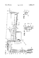
- FIG. 1 is a part diagrammatical, part schematical, part cross-sectional view of a water well system made in accordance with the present invention
- FIG. 2 is a cross-sectional view taken along line 2--2 of FIG. 1;
- FIG. 3 is a cross-sectional view taken along line 3--3 of FIG. 1.
- FIG. 1 a water well system 10.
- the system includes the usual borehole which can be cased as noted by numeral 12.
- the casing terminates in a wellhead 14, preferably located above ground level.
- a submersible type pump 18 is located downhole in the borehole below the liquid level 19.
- Numeral 20 generally indicates an aquifer which provides water for the pump.
- Other type pumps such as jet pumps, rod pumps, and the like can also be advantageously used in conjunction with the present invention.
- a pair of prior art check valves 24 and 26 are arranged in spaced relationship respective to one another, so that after the pump has cycled, a small stream of water can exit at 24 while air enters the system at 26; consequently, during the next cycle of operation, a short leg of air will be transferred into the storage tank 42 of the present invention, the details of which will be more fully discussed later on in this disclosure.
- Valve 28 preferably is located upstream of a double pipe T 30.
- a control 32 of conventional design is connected to the production pipe and to a suitable source of electrical current.
- An electrical conductor 34 extends through packing 36 and to a motor 38 of the submersible pump so that the control actuates the pump motor at the appropriate time.
- Valve 29 is placed within pipe 40 which has an outlet 41 disposed within storage tank 42, made in accordance with the present invention.
- the storage tank includes a relatively short vertical leg 44 which terminates at the lower end thereof as a blow-down or drain 46.
- the drain system includes a valve 48 located above the ground level.
- a supply pipe 50 is connected to the outermost and lowermost interior position of a lateral leg 52 and includes a valve 54 leading to the point of water consumption.
- Both the vertical and lateral legs of the tank include a water level 56 which separates a liquid phase 58 from a gaseous phase 60.
- the lower edge portion 61 where the vertical and lateral legs are joined together provides a divider which separates the liquid contained within the vertical and lateral legs from one another when the liquid level 56 recedes below the divider 61. Accordingly, when the tank is full, the interior thereof is comprised of a common gaseous phase and a common liquid phase, noting that liquid level 56 is common to both legs in this instance.
- liquid level 56 recedes below the edge of the divider 61, there is formed two separate liquid levels, and the liquid level of the lateral leg in this instance can continue to recede substantially far below the liquid level of the vertical leg as water continues to be used through valve 54.
- Numeral 62 indicates the longitudinal axial centerline of the lateral leg while numeral 64 indicates the longitudinal axial centerline of the vertical leg.
- the two centerline instersect one another at an angle less than 90°, noting that the lateral leg is bent below the horizontal when the vertical leg is vertically aligned respective to the horizontal.
- Numeral 66 of FIG. 2 illustrates the vertical height or length of the vertical leg of the tank, while numeral 68 of FIG. 1 indicates the length of the lateral leg. Numeral 70 illustrates the depth that the storage tank is buried below the surface of the ground.
- controller 32 When the pressure within the storage tank is reduced to a predetermined amount, for example 40 psi, controller 32 connects the illustrated source S of current to the pump motor 38, thereby energizing the pump and causing water to flow up the production tubing 22. Air captured between check valves 24 and 26 is forced up through the production tubing, through the open valves 28 and 29, and into the vertical leg 44 of the storage tank. The liquid level within the storage tank commences to rise, with any debris produced by the pump being accumulated in the bottom of the vertical leg. The liquid level continues to rise until the pressure of the air within the gas phase 60 reaches a predetermined amount, preferably 60 psi, whereupon the controller 32 interrupts the flow of current to the motor.
- a predetermined amount for example 40 psi
- valve 24 will open, permitting air to enter check valve 26, so that a short leg of air is provided.
- the liquid level 56 again recedes below the divider 61, and no matter how much of the liquid 58 is consumed, there will be no contaminates flowing through line 50 because the contaminated water is captured within the vertical leg.
- valve 48 is opened in order to translocate the debris contained within the lower chamber of the vertical leg out of the storage tank.
- valves 28, 29, and 48 it is preferred to insulate all of the above ground connections so as to enable the valves 28, 29, and 48 to be readily available, and to enable the pump to be easily serviced without incurring unnecessary labor charges.
- the storage tank can be buried 8-10" below the surface of the earth in geographical locations having mild winters, as found in Odessa, Tex., for example.
- the lateral and vertical legs may be made 12" in diameter where the vertical leg is 24" in length and the lateral leg is 8-12 feet in length.
- a tank capacity of 80-100 gallons is adequate for most domestic purposes.
- the present water system provides a trouble free supply of uncontaminated water for either domestic or commercial use.
Landscapes
- Engineering & Computer Science (AREA)
- Health & Medical Sciences (AREA)
- Life Sciences & Earth Sciences (AREA)
- Hydrology & Water Resources (AREA)
- Public Health (AREA)
- Water Supply & Treatment (AREA)
- Structural Engineering (AREA)
- Environmental & Geological Engineering (AREA)
- Structures Of Non-Positive Displacement Pumps (AREA)
- Jet Pumps And Other Pumps (AREA)
Abstract
Description
Claims (4)
Priority Applications (1)
| Application Number | Priority Date | Filing Date | Title |
|---|---|---|---|
| US06/291,902 US4400271A (en) | 1981-08-11 | 1981-08-11 | Captive air system for water well |
Applications Claiming Priority (1)
| Application Number | Priority Date | Filing Date | Title |
|---|---|---|---|
| US06/291,902 US4400271A (en) | 1981-08-11 | 1981-08-11 | Captive air system for water well |
Publications (1)
| Publication Number | Publication Date |
|---|---|
| US4400271A true US4400271A (en) | 1983-08-23 |
Family
ID=23122361
Family Applications (1)
| Application Number | Title | Priority Date | Filing Date |
|---|---|---|---|
| US06/291,902 Expired - Fee Related US4400271A (en) | 1981-08-11 | 1981-08-11 | Captive air system for water well |
Country Status (1)
| Country | Link |
|---|---|
| US (1) | US4400271A (en) |
Cited By (13)
| Publication number | Priority date | Publication date | Assignee | Title |
|---|---|---|---|---|
| US4582610A (en) * | 1985-09-03 | 1986-04-15 | Martin Baker | Well water aeration system |
| US5699859A (en) * | 1996-03-11 | 1997-12-23 | Poirier; Blair J. | Well water recirculation valve and method of manufacturing thereof |
| US20110198071A1 (en) * | 2010-02-16 | 2011-08-18 | Speciality Earth Sciences | Process for insitu treatment of soil and groundwater |
| US8551345B2 (en) * | 2010-05-03 | 2013-10-08 | Petroleos De Venezuela, S.A. | Production fluid solid trap |
| CN103669476A (en) * | 2013-12-28 | 2014-03-26 | 陈科 | Water intake facility without electric energy consumption |
| CN103882912A (en) * | 2014-03-28 | 2014-06-25 | 中国地质大学(武汉) | Home-position arsenic removal single well based on siderite filter materials |
| CN104805887A (en) * | 2015-03-09 | 2015-07-29 | 顾飞华 | Intelligent water supply system applied to water well |
| US9327214B2 (en) | 2012-02-13 | 2016-05-03 | Specialized Desanders Inc. | Desanding apparatus and a method of using same |
| US9861921B2 (en) | 2013-12-16 | 2018-01-09 | Specialized Desanders Inc. | Desanding apparatus and a method of using the same |
| US9909405B2 (en) | 2012-02-13 | 2018-03-06 | Specialized Desanders Inc. | Desanding apparatus and a method of using same |
| US9938812B2 (en) | 2012-02-13 | 2018-04-10 | Specialized Desanders Inc. | Desanding apparatus and a method of using same |
| US10450211B1 (en) | 2015-09-29 | 2019-10-22 | Keith Julian | Aeration system for water well |
| US10647045B1 (en) | 2016-11-03 | 2020-05-12 | Specialty Earth Sciences, Llc | Shaped or sized encapsulated reactant and method of making |
Citations (12)
| Publication number | Priority date | Publication date | Assignee | Title |
|---|---|---|---|---|
| US382188A (en) * | 1888-05-01 | Means and apparatus for collecting and separating sewage | ||
| US578686A (en) * | 1897-03-09 | Herbert b | ||
| US1119882A (en) * | 1913-07-18 | 1914-12-08 | Charles Daniel Ryder | Water-pipe system. |
| US1407936A (en) * | 1918-03-07 | 1922-02-28 | Charles Blumenthal | Apparatus and method for separating matter from effluents |
| US1459997A (en) * | 1922-03-28 | 1923-06-26 | Hargus G Shelly | Boiler cleaner |
| US1494670A (en) * | 1923-07-27 | 1924-05-20 | Delaney Rasneor Company Inc | Separator for flowing oil wells |
| US1496090A (en) * | 1922-07-05 | 1924-06-03 | William M Marker | Trapped outlet separator |
| US1762538A (en) * | 1923-04-16 | 1930-06-10 | Petroleum Rectifying Co | Water-level-controlling device |
| US2002407A (en) * | 1933-12-06 | 1935-05-21 | Hugo C Lemke | Fuel storage tank |
| US2061781A (en) * | 1935-10-24 | 1936-11-24 | Stein Hyman | Receptacle for catch basins or the like |
| US2423793A (en) * | 1944-02-02 | 1947-07-08 | Walter L Olivo | Oil and water separator having a collecting pipe and a stratification pipe therebelow |
| US3181700A (en) * | 1962-04-26 | 1965-05-04 | James C Hesson | Immiscible liquids separator |
-
1981
- 1981-08-11 US US06/291,902 patent/US4400271A/en not_active Expired - Fee Related
Patent Citations (12)
| Publication number | Priority date | Publication date | Assignee | Title |
|---|---|---|---|---|
| US382188A (en) * | 1888-05-01 | Means and apparatus for collecting and separating sewage | ||
| US578686A (en) * | 1897-03-09 | Herbert b | ||
| US1119882A (en) * | 1913-07-18 | 1914-12-08 | Charles Daniel Ryder | Water-pipe system. |
| US1407936A (en) * | 1918-03-07 | 1922-02-28 | Charles Blumenthal | Apparatus and method for separating matter from effluents |
| US1459997A (en) * | 1922-03-28 | 1923-06-26 | Hargus G Shelly | Boiler cleaner |
| US1496090A (en) * | 1922-07-05 | 1924-06-03 | William M Marker | Trapped outlet separator |
| US1762538A (en) * | 1923-04-16 | 1930-06-10 | Petroleum Rectifying Co | Water-level-controlling device |
| US1494670A (en) * | 1923-07-27 | 1924-05-20 | Delaney Rasneor Company Inc | Separator for flowing oil wells |
| US2002407A (en) * | 1933-12-06 | 1935-05-21 | Hugo C Lemke | Fuel storage tank |
| US2061781A (en) * | 1935-10-24 | 1936-11-24 | Stein Hyman | Receptacle for catch basins or the like |
| US2423793A (en) * | 1944-02-02 | 1947-07-08 | Walter L Olivo | Oil and water separator having a collecting pipe and a stratification pipe therebelow |
| US3181700A (en) * | 1962-04-26 | 1965-05-04 | James C Hesson | Immiscible liquids separator |
Cited By (17)
| Publication number | Priority date | Publication date | Assignee | Title |
|---|---|---|---|---|
| US4582610A (en) * | 1985-09-03 | 1986-04-15 | Martin Baker | Well water aeration system |
| US5699859A (en) * | 1996-03-11 | 1997-12-23 | Poirier; Blair J. | Well water recirculation valve and method of manufacturing thereof |
| US20110198071A1 (en) * | 2010-02-16 | 2011-08-18 | Speciality Earth Sciences | Process for insitu treatment of soil and groundwater |
| US8210773B2 (en) | 2010-02-16 | 2012-07-03 | Specialty Earth Sciences | Process for insitu treatment of soil and groundwater |
| US8366350B2 (en) | 2010-02-16 | 2013-02-05 | Specialty Earth Sciences | Process for insitu treatment of soil and groundwater |
| US9061333B2 (en) | 2010-02-16 | 2015-06-23 | Specialty Earth Sciences, Llc | Process for insitu treatment of soil and groundwater |
| US8551345B2 (en) * | 2010-05-03 | 2013-10-08 | Petroleos De Venezuela, S.A. | Production fluid solid trap |
| US9327214B2 (en) | 2012-02-13 | 2016-05-03 | Specialized Desanders Inc. | Desanding apparatus and a method of using same |
| US9938812B2 (en) | 2012-02-13 | 2018-04-10 | Specialized Desanders Inc. | Desanding apparatus and a method of using same |
| US9909405B2 (en) | 2012-02-13 | 2018-03-06 | Specialized Desanders Inc. | Desanding apparatus and a method of using same |
| US9861921B2 (en) | 2013-12-16 | 2018-01-09 | Specialized Desanders Inc. | Desanding apparatus and a method of using the same |
| CN103669476B (en) * | 2013-12-28 | 2015-06-17 | 陈科 | Water intake facility without electric energy consumption |
| CN103669476A (en) * | 2013-12-28 | 2014-03-26 | 陈科 | Water intake facility without electric energy consumption |
| CN103882912A (en) * | 2014-03-28 | 2014-06-25 | 中国地质大学(武汉) | Home-position arsenic removal single well based on siderite filter materials |
| CN104805887A (en) * | 2015-03-09 | 2015-07-29 | 顾飞华 | Intelligent water supply system applied to water well |
| US10450211B1 (en) | 2015-09-29 | 2019-10-22 | Keith Julian | Aeration system for water well |
| US10647045B1 (en) | 2016-11-03 | 2020-05-12 | Specialty Earth Sciences, Llc | Shaped or sized encapsulated reactant and method of making |
Similar Documents
| Publication | Publication Date | Title |
|---|---|---|
| US4400271A (en) | Captive air system for water well | |
| US5873410A (en) | Method and installation for pumping an oil-well effluent | |
| US7232524B2 (en) | Methods and apparatus for increasing and extending oil production from underground formations nearly depleted of natural gas drive | |
| US5033550A (en) | Well production method | |
| US6325152B1 (en) | Method and apparatus for increasing fluid recovery from a subterranean formation | |
| US5154588A (en) | System for pumping fluids from horizontal wells | |
| US5490562A (en) | Subsea flow enhancer | |
| US2300348A (en) | Method for cleaning oil wells | |
| US8215407B2 (en) | Apparatus for fluidizing formation fines settling in production well | |
| US8316938B2 (en) | Subterranean water production, transfer and injection method and apparatus | |
| US5271725A (en) | System for pumping fluids from horizontal wells | |
| US7243721B2 (en) | Methods and apparatus for heating oil production reservoirs | |
| CN104533356A (en) | Two-layer self-control layered oil production method and layered oil production method | |
| RU2005112794A (en) | PUMPING PACKING UNIT FOR A WELL WITH ONE OR MULTIPLE OBJECTS | |
| US20130327497A1 (en) | Method of heating/cooling structure using geothermal system | |
| US6209651B1 (en) | Well production apparatus and method | |
| US2194616A (en) | Means for operating oil wells | |
| US4649994A (en) | Installation for bringing hydrocarbon deposits into production with reinjection of effluents into the deposit or into the well or wells | |
| US6196310B1 (en) | Well production apparatus | |
| US6234248B1 (en) | Well production apparatus | |
| CA2657215C (en) | Liquid purge valve | |
| CA2350453C (en) | Method and apparatus for removing water from well-bore of gas wells to permit efficient production of gas | |
| US336327A (en) | Automatic water-works | |
| US6138763A (en) | Method for pumping a fluid | |
| US6199631B1 (en) | Well production apparatus |
Legal Events
| Date | Code | Title | Description |
|---|---|---|---|
| CC | Certificate of correction | ||
| AS | Assignment |
Owner name: STRMISKA, DENNIS L., P.O. BOX 306, KENEDY, TX. 78 Free format text: ASSIGNMENT OF ASSIGNORS INTEREST.;ASSIGNOR:LUNCEFORD, RANDY L.;REEL/FRAME:004339/0263 Effective date: 19841204 Owner name: D-N WEED & PEST CONTROL, INC., P.O. BOX 306, KENED Free format text: ASSIGNMENT OF ASSIGNORS INTEREST.;ASSIGNOR:LUNCEFORD, RANDY L.;REEL/FRAME:004339/0263 Effective date: 19841204 Owner name: STRMISKA, DENNIS L.,TEXAS Free format text: ASSIGNMENT OF ASSIGNORS INTEREST;ASSIGNOR:LUNCEFORD, RANDY L.;REEL/FRAME:004339/0263 Effective date: 19841204 Owner name: D-N WEED & PEST CONTROL, INC.,TEXAS Free format text: ASSIGNMENT OF ASSIGNORS INTEREST;ASSIGNOR:LUNCEFORD, RANDY L.;REEL/FRAME:004339/0263 Effective date: 19841204 |
|
| FEPP | Fee payment procedure |
Free format text: MAINTENANCE FEE REMINDER MAILED (ORIGINAL EVENT CODE: REM.); ENTITY STATUS OF PATENT OWNER: SMALL ENTITY |
|
| FEPP | Fee payment procedure |
Free format text: SURCHARGE FOR LATE PAYMENT, PL 96-517 (ORIGINAL EVENT CODE: M176); ENTITY STATUS OF PATENT OWNER: SMALL ENTITY |
|
| MAFP | Maintenance fee payment |
Free format text: PAYMENT OF MAINTENANCE FEE, 4TH YEAR, PL 96-517 (ORIGINAL EVENT CODE: M170); ENTITY STATUS OF PATENT OWNER: SMALL ENTITY Year of fee payment: 4 |
|
| MAFP | Maintenance fee payment |
Free format text: PAYMENT OF MAINTENANCE FEE, 8TH YEAR, PL 96-517 (ORIGINAL EVENT CODE: M171); ENTITY STATUS OF PATENT OWNER: SMALL ENTITY Year of fee payment: 8 |
|
| FEPP | Fee payment procedure |
Free format text: MAINTENANCE FEE REMINDER MAILED (ORIGINAL EVENT CODE: REM.); ENTITY STATUS OF PATENT OWNER: SMALL ENTITY |
|
| LAPS | Lapse for failure to pay maintenance fees | ||
| FP | Lapsed due to failure to pay maintenance fee |
Effective date: 19950823 |
|
| STCH | Information on status: patent discontinuation |
Free format text: PATENT EXPIRED DUE TO NONPAYMENT OF MAINTENANCE FEES UNDER 37 CFR 1.362 |