US4399867A - Method for injecting a gaseous stream into a hot subterranean zone - Google Patents
Method for injecting a gaseous stream into a hot subterranean zone Download PDFInfo
- Publication number
- US4399867A US4399867A US06/263,625 US26362581A US4399867A US 4399867 A US4399867 A US 4399867A US 26362581 A US26362581 A US 26362581A US 4399867 A US4399867 A US 4399867A
- Authority
- US
- United States
- Prior art keywords
- casing
- subterranean zone
- gaseous stream
- zone
- temp
- Prior art date
- Legal status (The legal status is an assumption and is not a legal conclusion. Google has not performed a legal analysis and makes no representation as to the accuracy of the status listed.)
- Expired - Fee Related
Links
- 238000000034 method Methods 0.000 title claims abstract description 40
- 238000004891 communication Methods 0.000 claims abstract description 3
- 239000012530 fluid Substances 0.000 claims abstract description 3
- QVGXLLKOCUKJST-UHFFFAOYSA-N atomic oxygen Chemical compound [O] QVGXLLKOCUKJST-UHFFFAOYSA-N 0.000 claims description 22
- 229910052760 oxygen Inorganic materials 0.000 claims description 22
- 239000001301 oxygen Substances 0.000 claims description 22
- 239000007789 gas Substances 0.000 claims description 15
- CURLTUGMZLYLDI-UHFFFAOYSA-N Carbon dioxide Chemical compound O=C=O CURLTUGMZLYLDI-UHFFFAOYSA-N 0.000 claims description 14
- 239000003245 coal Substances 0.000 claims description 11
- 229910002092 carbon dioxide Inorganic materials 0.000 claims description 7
- 239000001569 carbon dioxide Substances 0.000 claims description 7
- 238000002309 gasification Methods 0.000 claims description 5
- 239000011810 insulating material Substances 0.000 claims 2
- 239000000203 mixture Substances 0.000 claims 2
- 238000009413 insulation Methods 0.000 description 22
- 238000002347 injection Methods 0.000 description 17
- 239000007924 injection Substances 0.000 description 17
- 239000000463 material Substances 0.000 description 11
- 230000015572 biosynthetic process Effects 0.000 description 9
- 238000009434 installation Methods 0.000 description 6
- 238000010586 diagram Methods 0.000 description 4
- 239000008246 gaseous mixture Substances 0.000 description 4
- RVTZCBVAJQQJTK-UHFFFAOYSA-N oxygen(2-);zirconium(4+) Chemical compound [O-2].[O-2].[Zr+4] RVTZCBVAJQQJTK-UHFFFAOYSA-N 0.000 description 4
- 229910001928 zirconium oxide Inorganic materials 0.000 description 4
- 239000004568 cement Substances 0.000 description 3
- 238000002485 combustion reaction Methods 0.000 description 3
- 238000001816 cooling Methods 0.000 description 3
- 238000011065 in-situ storage Methods 0.000 description 3
- 239000003208 petroleum Substances 0.000 description 3
- 238000011084 recovery Methods 0.000 description 3
- 239000003079 shale oil Substances 0.000 description 3
- 238000010793 Steam injection (oil industry) Methods 0.000 description 2
- 239000011248 coating agent Substances 0.000 description 2
- 238000000576 coating method Methods 0.000 description 2
- 238000004519 manufacturing process Methods 0.000 description 2
- 238000002844 melting Methods 0.000 description 2
- 230000008018 melting Effects 0.000 description 2
- 229910052751 metal Inorganic materials 0.000 description 2
- 239000002184 metal Substances 0.000 description 2
- 238000012546 transfer Methods 0.000 description 2
- 229910000851 Alloy steel Inorganic materials 0.000 description 1
- OKTJSMMVPCPJKN-UHFFFAOYSA-N Carbon Chemical compound [C] OKTJSMMVPCPJKN-UHFFFAOYSA-N 0.000 description 1
- 229910000975 Carbon steel Inorganic materials 0.000 description 1
- 239000000470 constituent Substances 0.000 description 1
- 230000001419 dependent effect Effects 0.000 description 1
- 238000013461 design Methods 0.000 description 1
- 239000003085 diluting agent Substances 0.000 description 1
- 239000000835 fiber Substances 0.000 description 1
- 238000012423 maintenance Methods 0.000 description 1
- 238000012986 modification Methods 0.000 description 1
- 230000004048 modification Effects 0.000 description 1
- TWNQGVIAIRXVLR-UHFFFAOYSA-N oxo(oxoalumanyloxy)alumane Chemical compound O=[Al]O[Al]=O TWNQGVIAIRXVLR-UHFFFAOYSA-N 0.000 description 1
- -1 per se Chemical compound 0.000 description 1
- 238000007750 plasma spraying Methods 0.000 description 1
- 238000002360 preparation method Methods 0.000 description 1
- 239000000376 reactant Substances 0.000 description 1
- 239000007787 solid Substances 0.000 description 1
- 230000003313 weakening effect Effects 0.000 description 1
Images

Classifications
-
- E—FIXED CONSTRUCTIONS
- E21—EARTH OR ROCK DRILLING; MINING
- E21B—EARTH OR ROCK DRILLING; OBTAINING OIL, GAS, WATER, SOLUBLE OR MELTABLE MATERIALS OR A SLURRY OF MINERALS FROM WELLS
- E21B33/00—Sealing or packing boreholes or wells
- E21B33/10—Sealing or packing boreholes or wells in the borehole
- E21B33/13—Methods or devices for cementing, for plugging holes, crevices or the like
- E21B33/14—Methods or devices for cementing, for plugging holes, crevices or the like for cementing casings into boreholes
-
- E—FIXED CONSTRUCTIONS
- E21—EARTH OR ROCK DRILLING; MINING
- E21B—EARTH OR ROCK DRILLING; OBTAINING OIL, GAS, WATER, SOLUBLE OR MELTABLE MATERIALS OR A SLURRY OF MINERALS FROM WELLS
- E21B17/00—Drilling rods or pipes; Flexible drill strings; Kellies; Drill collars; Sucker rods; Cables; Casings; Tubings
-
- E—FIXED CONSTRUCTIONS
- E21—EARTH OR ROCK DRILLING; MINING
- E21B—EARTH OR ROCK DRILLING; OBTAINING OIL, GAS, WATER, SOLUBLE OR MELTABLE MATERIALS OR A SLURRY OF MINERALS FROM WELLS
- E21B36/00—Heating, cooling or insulating arrangements for boreholes or wells, e.g. for use in permafrost zones
- E21B36/003—Insulating arrangements
Definitions
- This invention relates to a method for injecting a gaseous stream into a hot subterranean zone.
- This invention further relates to an apparatus for injecting a gaseous stream into a hot subterranean zone.
- a frequently occurring problem relates to the maintenance of a casing from the surface to the subterranean zone to inject gaseous streams into the subterranean zone.
- problems arise frequently in the in situ gasification of coal deposits.
- problems arise because the temperatures in the in situ gasification zone may be in excess of 3,000° F. At such temperatures typical casing and tubing materials tend to melt, weaken or otherwise become unsuitable for the continued injection of gaseous or other streams into the subterranean zone.
- the weakening of the casing may be a contributing factor to the ultimate collapse of the well structure into the subterranean zone with a resulting loss of ability to continue the injection of gas or other streams.
- Similar problems arise in the injection of gaseous streams into subterranean zones wherein shale oil deposits or petroleum deposits are being subjected to high temperature treatment for the recovery of heat values from the deposit.
- the gaseous stream injected in many instances contains steam or other constituents such as carbon dioxide or the like, in addition to a free oxygen-containing gas to support combustion.
- the design and operation of such wells has been a continuing problem and a continuing search is underway to develop improved methods for the installation and use of such wells.
- gaseous streams may be readily and reliably injected into a hot subterranean zone by a method consisting essentially of (a) positioning a casing means in fluid communication with the hot subterranean zone and the surface; (b) insulating a lower portion of the outer surface of the casing, the lower portion including the portion of the casing in the hot subterranean zone; and (c) injecting the gaseous stream into the hot subterranean zone through the casing at a rate sufficient to maintain the casing below a selected maximum temperature.
- An apparatus comprising: (a) a casing fluidly communicating the hot subterranean zone and the surface; (b) insulation positioned on the outer surface of a lower portion of the casing, the lower portion including the portion of the casing in the hot zone; and (c) an injection means adapted to inject a gaseous stream into an upper end of the casing at a flow rate through said casing in excess of 5 lb./sec./ft 2 is useful in the practice of the method.
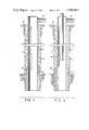
- FIG. 1 is a schematic diagram of an embodiment of an apparatus useful in the practice of the method of the present invention
- FIG. 2 is a schematic diagram of a further embodiment of the apparatus set forth in FIG. 1;
- FIG. 3 is a schematic diagram of a further embodiment of the apparatus set forth in FIG. 1;
- FIG. 4 is a schematic diagram of the installation of insulation on the lower portion of the casing shown in FIG. 1.
- FIG. 1 a casing 16 is shown in position in a wellbore 10 so that it fluidly communicates the surface 12 and a subterranean zone 14.
- a gas inlet 18 is provided for the injection of gas into casing 16 for injection into subterranean zone 14.
- Casing 16 is normally cemented in place by cement 22 positioned about casing 16 to fill the annular space between the outer diameter of casing 16 and the inner diameter of wellbore 10. The use of cement to position casings in wellbores is well known to the art and will not be discussed further.
- a lower portion 24 of casing 16 includes insulation 20 positioned about its outer surface. Lower portion 24 normally comprises the portion of casing 16 exposed to formation 14 and extends for a suitable distance above formation 14 to avoid the exposure of uninsulated casing to elevated temperatures.
- casing 16 In the installation of casing 16, wellbore 10 is typically drilled from surface 12 to the total depth to which casing 16 is to be set. Casing 16 is then positioned in wellbore 10 and cemented in place by the use of a cement shoe or the like. Insulation 20 is typically placed on the outer surface of casing 16 in the zones of interest prior to positioning casing 16 in wellbore 10 so that the insulation is in place as casing 16 is cemented in place.
- a gaseous mixture comprising steam, carbon dioxide, free oxygen and the like, is injected through gas inlet 18 into casing 16 and downwardly through casing 16 into formation 14.
- the gaseous mixture is typically selected to gasify or partially combust the coal deposit with the gases typically being recovered from a nearby production well. Forward or reverse combustion can be used but in many instances it is found that very high temperatures exist either upon ignition or at some time during the life of the injection wells.
- the injected gaseous mixture may be varied widely depending upon the particular requirements of the process being conducted.
- free oxygen is provided by the injection of free oxygen, per se, oxygen enriched air, air or the like.
- gaseous streams are readily injected through the apparatus shown to support combustion in the hot subterranean zone without the risk of casing collapse and the like.
- a tubing 26 is positioned in casing 16 for the injection of a second gaseous stream into casing 16.
- the operation of casing 16 and the associated apparatus is as described above with the exception that a second gaseous stream is injected through tubing 26.
- tubing 26 has been extended to the bottom of casing 16. Further, the lower portion of tubing 26 has been coated with a high-temperature coating 28, such as zirconium oxide, to extend the maximum operating temperature of tubing 26.
- a high-temperature coating 28 such as zirconium oxide
- a free oxygen-containing gas is injected through tubing 26 with steam, carbon dioxide, or a similar gas, being injected through casing 16.
- the steam, carbon dioxide, or the like is injected at a rate as described above to maintain the temperature of casing 16 below a selected maximum.
- the injection of the free oxygen-containing gas through tubing 26 is at a flow rate which can be independent of the rate at which steam, carbon dioxide, or the like, is injected through casing 16. Since tubing 26 is inside casing 16 it is of course maintained below the selected maximum temperature for casing 16. While tubing 26 is shown as extending somewhat below the bottom of casing 16, such may not be the case in practice and in many instances it is quite likely that the end of tubing 26 below casing 16 will be burned off.
- FIG. 4 the installation of the insulation on the outer diameter of casing 16 is shown in somewhat greater detail.
- a series of projections 30 are positioned on the outer surface of casing 16 to help retain insulation 20 in position.
- Insulation 20 may be sprayed on or it may be positioned by wrapping or otherwise about the outer surface of casing 16.
- a plurality of ropes 32 which are fabricated from the same material as the insulation are used to secure insulation 20 in place about casing 16.
- sections 36 of insulation have been fitted to cover joints 34 in casing 16.
- the insulation is also desirably encased in a sheath 38 which may be of any suitable material.
- the sheathing 38 is desirably positioned about insulation 20 to maintain it in position on casing 16 during installation.
- Sheathing 38 is normally not of a highly durable material since its primary function is to protect the insulation during installation. Sheathing 38 will normally burn off in exposed areas upon encountering high temperatures.
- casing 16 is installed in a formation prior to commencement of the process which results in the elevated temperatures in the subterranean formation, be it a shale oil, petroleum or coal deposit. While the method of the present invention and the apparatus of the present invention are useful in the practice of the recovery of heat values from substantially any subterranean carbonaceous formation, the use of the method and apparatus is considered to be particularly suitable for use in the in situ gasification of coal deposits.
- the wellbore is drilled and the casing installed prior to the ignition of the coal deposit in the vicinity of the wellbore. Thereafter, the casing as described above is protected against high temperatures encountered in the gasification of the coal deposit.
- the casing is normally fabricated from conventionally-used casing materials and the insulation used is desirably selected from materials which have melting points in excess of 3500° F.
- Some such materials are aluminum oxide, refractory fibers and the like as known to those skilled in the art. Such materials have melting points in excess of 3500° F. and are conventionally used for insulation in applications up to about 2600° F.
- the lower portion of tubing 26 may be coated with a refractory coating 28 such as zirconium oxide.
- a refractory coating 28 such as zirconium oxide.
- Zirconium oxide is typically applied by plasma spraying or the like and has been used to protect metal parts in aircraft engines, etc., up to temperatures of about 2800° F.
- the use of zirconium oxide to protect tubing 26 is optional, although in some instances its use may be preferred.
- the high gas flow rates are desirable to achieve the desired cooling of casing 16.
- Flow rates of at least 5 lb./sec./ft. 2 of cross-sectional area in casing 16 or in the annulus between the inner diameter of casing 16 and the outer diameter of tubing 26 are considered suitable.
- higher flow rates are required and it is preferred that flow rates greater than about 20 lb./sec./ft. 2 be used.
- higher flow rates than necessary for the injection of desired quantities of materials or for adequate cooling is not necessary.
- the amount of material required in the formation is dependent upon numerous variables well known to those skilled in the art.
- the temperature in casing 16 can be determined and the flow rates adjusted accordingly to maintain the casing temperature below a selected maximum. In most instances it is expected that flow rates greater than about 5 lb./sec./ft. 2 will be found suitable.
- the gaseous stream injected is injected at a relatively high velocity so that it effectively cools casing 16 as protected by insulation 20, thereby permitting the use of cased wells in temperature environments which are well in excess of the operating temperature of materials typically used for the fabrication of such casings.
- the use of the apparatus and method of the present invention permits the use of cased wells for the injection of free oxygen-containing gases into hot subterranean zones reliably and economically.
- gases can be recovered from such hot subterranean zones. While such is not the preferred use, it is pointed out that those skilled in the art may consider such variations desirable.
- the calculated solids temperature is about 2500° F.
- the calculations are based on the use of 4.5-inch outer diameter casing and 23/8-inch outer diameter tubing.
- the apparatus shown in FIG. 3 is used in all the examples below. All temperatures are in °F.
- Example 1 When the conditions in Example 1 are varied by increasing the process temperature to 3500° F. the following maximum temperatures can be calculated:
- Carbon and low alloy steel casings are typically used in such casing and tubing and will retain about 50% of their room temperature strength up to about 900° F. and about 20% of their room temperature strength up to about 1000° F. Thus, it is desirable to hold the metal temperature to below 900° F. in the casing.
- At the calculated process temperature of 2500° F. one inch of insulation would be adequate for heated lengths up to about 80 ft. at the low flow rate. Two inches would be adequate under all conditions and up to 100 ft. of heated length.
Landscapes
- Engineering & Computer Science (AREA)
- Life Sciences & Earth Sciences (AREA)
- Geology (AREA)
- Mining & Mineral Resources (AREA)
- Physics & Mathematics (AREA)
- Environmental & Geological Engineering (AREA)
- Fluid Mechanics (AREA)
- General Life Sciences & Earth Sciences (AREA)
- Geochemistry & Mineralogy (AREA)
- Mechanical Engineering (AREA)
- Physical Or Chemical Processes And Apparatus (AREA)
Abstract
Description
______________________________________
Oxygen - steam molal ratio
                     1
Steam temperature    350° F.
Heat loss to formation
                     45,000 B.T.U./hr.
______________________________________
 (based on a 10foot diameter cavity and coal thermal conductivity of 0.2
 B.T.U./Hr. ft. °F.)
              TABLE I
______________________________________
Length
of         Casing            Tubing
Heated     Wall    Steam     Wall  Oxygen
Zone (ft.) Temp.   Temp.     Temp. Temp.
______________________________________
0.0        529.    350.      350.  350.
10.        598.    428.      380.  358.
20.        655.    491.      415.  379.
30.        703.    545.      451.  408.
40.        745.    592.      489.  441.
50.        783.    635.      526.  476.
60.        818.    674.      564.  512.
70.        851.    712.      601.  549.
80.        883.    747.      537.  586.
90.        913.    781.      673.  622.
100.       943.    814.      707.  658.
______________________________________
              TABLE II
______________________________________
Length
of         Casing            Tubing
Heated     Wall    Steam     Wall  Oxygen
Zone (ft.) Temp.   Temp.     Temp. Temp.
______________________________________
0.0         967.    350.     350.  350.
10.        1178.    612.     453.  379.
20.        1343.    817.     566.  449.
30.        1477.    984.     682.  542.
40.        1591.   1126.     799.  647.
50.        1691.   1251.     914.  758.
60.        1782.   1363.     1026. 870.
70.        1864.   1466.     1135. 981.
80.        1941.   1561.     1239. 1090.
90.        2013.   1651.     1340. 1195.
100.       2081.   1736.     1436. 1296.
______________________________________
              TABLE III
______________________________________
Length
of         Casing            Tubing
Heated     Wall    Steam     Wall  Oxygen
Zone (ft.) Temp.   Temp.     Temp. Temp.
______________________________________
0.0        470.    350.      350.  350.
10.        518.    402.      370.  356.
20.        558.    446.      394.  370.
30.        593.    483.      419.  389.
40.        624.    516.      445.  412.
50.        652.    547.      471.  436.
60.        679.    576.      498.  462.
70.        704.    603.      524.  488.
80.        729.    629.      551.  514.
90.        752.    655.      576.  540.
100.       775.    679.      602.  566.
______________________________________
              TABLE IV
______________________________________
Length
of         Casing            Tubing
Heated     Wall    Steam     Wall  Oxygen
Zone (ft.) Temp.   Temp.     Temp. Temp.
______________________________________
0.0         776.    350.     350.  350.
10.         934.    533.     422.  370.
20.        1062.    681.     502.  419.
30.        1169.    805.     587.  486.
40.        1262.    913.     673.  562.
50.        1346.   1009.     760.  644.
60.        1422.   1098.     845.  727.
70.        1494.   1181.     929.  811.
80.        1562.   1259.     1010. 895.
90.        1626.   1333.     1090. 976.
100.       1687.   1404.     1167. 1056.
______________________________________
              TABLE V
______________________________________
Length
of         Casing            Tubing
Heated     Wall    Steam     Wall  Oxygen
Zone (ft.) Temp.   Temp.     Temp. Temp.
______________________________________
0.0        391.    350.      350.  350.
10.        404.    363.      355.  351.
20.        415.    374.      360.  353.
30.        425.    384.      366.  357.
40.        434.    394.      372.  362.
50.        442.    402.      378.  367.
60.        450.    411.      385.  373.
70.        458.    419.      391.  379.
80.        466.    426.      398.  385.
90.        473.    434.      405.  391.
100.       480.    441.      412.  398.
______________________________________
              TABLE VI
______________________________________
Length
of         Casing            Tubing
Heated     Wall    Steam     Wall  Oxygen
Zone (ft.) Temp.   Temp.     Temp. Temp.
______________________________________
0.0        504.    350.      350.  350.
10.        549.    397.      367.  354.
20.        588.    439.      387.  363.
30.        624.    476.      408.  376.
40.        656.    510.      430.  393.
50.        686.    542.      453.  412.
60.        714.    571.      477.  433.
70.        741.    599.      501.  455.
80.        767.    626.      525.  477.
90.        791.    652.      549.  501.
100.       816.    678.      573.  524.
______________________________________
              TABLE VII
______________________________________
Length
of         Casing            Tubing
Heated     Wall    Steam     Wall  Oxygen
Zone (ft.) Temp.   Temp.     Temp. Temp.
______________________________________
0.0        377.    350.      350.  350.
10.        385.    358.      353.  351.
20.        392.    366.      356.  352.
30.        399.    372.      360.  355.
40.        405.    378.      364.  358.
50.        410.    384.      368.  361.
60.        416.    390.      373.  365.
70.        421.    395.      377.  369.
80.        426.    400.      381.  373.
90.        431.    405.      386.  377.
100.       435.    409.      390.  381.
______________________________________
              TABLE VIII
______________________________________
Length
of         Casing            Tubing
Heated     Wall    Steam     Wall  Oxygen
Zone (ft.) Temp.   Temp.     Temp. Temp.
______________________________________
0.0        450.    350.      350.  350.
10.        480.    381.      361.  352.
20.        507.    408.      374.  358.
30.        531.    433.      388.  367.
40.        553.    456.      403.  378.
50.        573.    477.      418.  391.
60.        592.    497.      434.  405.
70.        611.    516.      450.  419.
80.        628.    534.      466.  434.
90.        646.    552.      482.  450.
100.       662.    569.      498.  466.
______________________________________
Claims (6)
Priority Applications (1)
| Application Number | Priority Date | Filing Date | Title |
|---|---|---|---|
| US06/263,625 US4399867A (en) | 1981-05-14 | 1981-05-14 | Method for injecting a gaseous stream into a hot subterranean zone |
Applications Claiming Priority (1)
| Application Number | Priority Date | Filing Date | Title |
|---|---|---|---|
| US06/263,625 US4399867A (en) | 1981-05-14 | 1981-05-14 | Method for injecting a gaseous stream into a hot subterranean zone |
Publications (1)
| Publication Number | Publication Date |
|---|---|
| US4399867A true US4399867A (en) | 1983-08-23 |
Family
ID=23002551
Family Applications (1)
| Application Number | Title | Priority Date | Filing Date |
|---|---|---|---|
| US06/263,625 Expired - Fee Related US4399867A (en) | 1981-05-14 | 1981-05-14 | Method for injecting a gaseous stream into a hot subterranean zone |
Country Status (1)
| Country | Link |
|---|---|
| US (1) | US4399867A (en) |
Cited By (1)
| Publication number | Priority date | Publication date | Assignee | Title |
|---|---|---|---|---|
| US20080023197A1 (en) * | 2006-07-25 | 2008-01-31 | Shurtleff J K | Apparatus, system, and method for in-situ extraction of hydrocarbons |
Citations (12)
| Publication number | Priority date | Publication date | Assignee | Title |
|---|---|---|---|---|
| US1804078A (en) * | 1928-11-26 | 1931-05-05 | Baden Martin William | Means for preventing corrosion in pipes |
| US2148717A (en) * | 1937-01-21 | 1939-02-28 | Alvin M Whitney | Process of extracting oil from oil sands |
| US3130264A (en) * | 1962-02-23 | 1964-04-21 | Rca Corp | Tuning system |
| US3142336A (en) * | 1960-07-18 | 1964-07-28 | Shell Oil Co | Method and apparatus for injecting steam into subsurface formations |
| US3221813A (en) * | 1963-08-12 | 1965-12-07 | Shell Oil Co | Recovery of viscous petroleum materials |
| US3358756A (en) * | 1965-03-12 | 1967-12-19 | Shell Oil Co | Method for in situ recovery of solid or semi-solid petroleum deposits |
| US3372754A (en) * | 1966-05-31 | 1968-03-12 | Mobil Oil Corp | Well assembly for heating a subterranean formation |
| CA783427A (en) * | 1968-04-23 | Equity Oil Company | Recovery of petroleum products from oil shale | |
| US3760876A (en) * | 1972-05-11 | 1973-09-25 | Mobil Oil Corp | Well completion systems |
| US3820605A (en) * | 1971-02-16 | 1974-06-28 | Upjohn Co | Apparatus and method for thermally insulating an oil well |
| US3878312A (en) * | 1973-12-17 | 1975-04-15 | Gen Electric | Composite insulating barrier |
| US4147213A (en) * | 1978-02-22 | 1979-04-03 | Standard Oil Company (Indiana) | Combustion air injection well |
-
1981
- 1981-05-14 US US06/263,625 patent/US4399867A/en not_active Expired - Fee Related
Patent Citations (12)
| Publication number | Priority date | Publication date | Assignee | Title |
|---|---|---|---|---|
| CA783427A (en) * | 1968-04-23 | Equity Oil Company | Recovery of petroleum products from oil shale | |
| US1804078A (en) * | 1928-11-26 | 1931-05-05 | Baden Martin William | Means for preventing corrosion in pipes |
| US2148717A (en) * | 1937-01-21 | 1939-02-28 | Alvin M Whitney | Process of extracting oil from oil sands |
| US3142336A (en) * | 1960-07-18 | 1964-07-28 | Shell Oil Co | Method and apparatus for injecting steam into subsurface formations |
| US3130264A (en) * | 1962-02-23 | 1964-04-21 | Rca Corp | Tuning system |
| US3221813A (en) * | 1963-08-12 | 1965-12-07 | Shell Oil Co | Recovery of viscous petroleum materials |
| US3358756A (en) * | 1965-03-12 | 1967-12-19 | Shell Oil Co | Method for in situ recovery of solid or semi-solid petroleum deposits |
| US3372754A (en) * | 1966-05-31 | 1968-03-12 | Mobil Oil Corp | Well assembly for heating a subterranean formation |
| US3820605A (en) * | 1971-02-16 | 1974-06-28 | Upjohn Co | Apparatus and method for thermally insulating an oil well |
| US3760876A (en) * | 1972-05-11 | 1973-09-25 | Mobil Oil Corp | Well completion systems |
| US3878312A (en) * | 1973-12-17 | 1975-04-15 | Gen Electric | Composite insulating barrier |
| US4147213A (en) * | 1978-02-22 | 1979-04-03 | Standard Oil Company (Indiana) | Combustion air injection well |
Cited By (2)
| Publication number | Priority date | Publication date | Assignee | Title |
|---|---|---|---|---|
| US20080023197A1 (en) * | 2006-07-25 | 2008-01-31 | Shurtleff J K | Apparatus, system, and method for in-situ extraction of hydrocarbons |
| US8205674B2 (en) * | 2006-07-25 | 2012-06-26 | Mountain West Energy Inc. | Apparatus, system, and method for in-situ extraction of hydrocarbons |
Similar Documents
| Publication | Publication Date | Title |
|---|---|---|
| US7640965B2 (en) | Creating a well abandonment plug | |
| US4185692A (en) | Underground linkage of wells for production of coal in situ | |
| US4421169A (en) | Protective sheath for high temperature process wells | |
| US4566536A (en) | Method for operating an injection well in an in-situ combustion oil recovery using oxygen | |
| CA1289868C (en) | Oil recovery | |
| US6079499A (en) | Heater well method and apparatus | |
| US3007521A (en) | Recovery of oil by in situ combustion | |
| US3372754A (en) | Well assembly for heating a subterranean formation | |
| AU2002346437A1 (en) | In-situ casting of well equipment | |
| CN106761653A (en) | For the shower nozzle equipment and its operating method of coal underground gasifying technology | |
| CN106089179B (en) | For the withdrawal well equipment of Underground Coal Gasification Process and its application | |
| US5488990A (en) | Apparatus and method for generating inert gas and heating injected gas | |
| US3856084A (en) | An improved blind borehole back-reaming method | |
| US4436153A (en) | In-situ combustion method for controlled thermal linking of wells | |
| AU2002212320B2 (en) | In-situ combustion for oil recovery | |
| US3053321A (en) | Thermodynamic packer | |
| US3160208A (en) | Production well assembly for in situ combustion | |
| US3525399A (en) | Technique for insulating a wellbore with silicate foam | |
| US4399867A (en) | Method for injecting a gaseous stream into a hot subterranean zone | |
| US3630278A (en) | Method for strengthening reservoir fractures | |
| US3343598A (en) | Protection of production well equipment in in situ combustion operation | |
| US4459101A (en) | Burner systems | |
| US4901796A (en) | Well packing system | |
| US3414055A (en) | Formation consolidation using a combustible liner | |
| US3147805A (en) | Method for consolidating an unconsolidated formation |
Legal Events
| Date | Code | Title | Description |
|---|---|---|---|
| AS | Assignment |
Owner name: ATLANTIC RICHFIELD COMPANY, LOS ANGELES,CA. A CORP Free format text: ASSIGNMENT OF ASSIGNORS INTEREST.;ASSIGNOR:WOLCOTT, HERBERT B.;REEL/FRAME:004134/0261 Effective date: 19810511 Owner name: ATLANTIC RICHFIELD COMPANY, A CORP OF PA, CALIFORN Free format text: ASSIGNMENT OF ASSIGNORS INTEREST;ASSIGNOR:WOLCOTT, HERBERT B.;REEL/FRAME:004134/0261 Effective date: 19810511 |
|
| MAFP | Maintenance fee payment |
Free format text: PAYMENT OF MAINTENANCE FEE, 4TH YEAR, PL 96-517 (ORIGINAL EVENT CODE: M170); ENTITY STATUS OF PATENT OWNER: LARGE ENTITY Year of fee payment: 4 |
|
| FEPP | Fee payment procedure |
Free format text: PAYOR NUMBER ASSIGNED (ORIGINAL EVENT CODE: ASPN); ENTITY STATUS OF PATENT OWNER: LARGE ENTITY |
|
| FEPP | Fee payment procedure |
Free format text: MAINTENANCE FEE REMINDER MAILED (ORIGINAL EVENT CODE: REM.); ENTITY STATUS OF PATENT OWNER: LARGE ENTITY |
|
| LAPS | Lapse for failure to pay maintenance fees | ||
| STCH | Information on status: patent discontinuation |
Free format text: PATENT EXPIRED DUE TO NONPAYMENT OF MAINTENANCE FEES UNDER 37 CFR 1.362 |
|
| FP | Lapsed due to failure to pay maintenance fee |
Effective date: 19910825 |