US4901796A - Well packing system - Google Patents
Well packing system Download PDFInfo
- Publication number
- US4901796A US4901796A US07/286,174 US28617488A US4901796A US 4901796 A US4901796 A US 4901796A US 28617488 A US28617488 A US 28617488A US 4901796 A US4901796 A US 4901796A
- Authority
- US
- United States
- Prior art keywords
- well
- packing
- casing
- zone
- diameter
- Prior art date
- Legal status (The legal status is an assumption and is not a legal conclusion. Google has not performed a legal analysis and makes no representation as to the accuracy of the status listed.)
- Expired - Fee Related
Links
Images


Classifications
-
- E—FIXED CONSTRUCTIONS
- E21—EARTH DRILLING; MINING
- E21B—EARTH DRILLING, e.g. DEEP DRILLING; OBTAINING OIL, GAS, WATER, SOLUBLE OR MELTABLE MATERIALS OR A SLURRY OF MINERALS FROM WELLS
- E21B35/00—Methods or apparatus for preventing or extinguishing fires
-
- E—FIXED CONSTRUCTIONS
- E21—EARTH DRILLING; MINING
- E21B—EARTH DRILLING, e.g. DEEP DRILLING; OBTAINING OIL, GAS, WATER, SOLUBLE OR MELTABLE MATERIALS OR A SLURRY OF MINERALS FROM WELLS
- E21B43/00—Methods or apparatus for obtaining oil, gas, water, soluble or meltable materials or a slurry of minerals from wells
- E21B43/02—Subsoil filtering
- E21B43/04—Gravelling of wells
Definitions
- the present invention pertains to packing which can be used in injection wellbores which facilitate the recovery of heavy oils, shale oils, tars, and in well shafts for in situ coal gasification.
- the packing can also be used in light oil and gas production wells.
- the packing is used to control the quantity of hydrocarbons in the wellbore of a producing well; to limit the backflow of hydrocarbons into and reduce space available to hydrocarbons within the wellbore of an injection well; and, to act as a heat sink in all applications, preventing damage to well components in case of a well fire or combustion in the immediate area of the well.
- In situ combustion is a generic term used to describe burning of hydrocarbons in a subterranean formation.
- In situ combustion in the form of fire flooding, is generally used in enhanced recovery of heavy oils and tar sands, and can be used in the recovery of light oils.
- In situ combustion can also be used for retorting oil shale.
- the well packing system of the present invention although focused on in-situ combustion for heavy oil recovery, is also applicable to tar sands, shale oil and light oil.
- the packing can also be used in well shafts for in-situ coal gasification processes.
- the in situ combustion process for enhanced heavy oil recovery is a thermal recovery technique in which a burning fuel front is initiated in the oil-containing formation near an injection well and is used to push heated oil toward production wells.
- a burning fuel front is initiated in the oil-containing formation near an injection well and is used to push heated oil toward production wells.
- the formation in which the oil lies is preheated with steam or a type of downhole heater; then oxygen containing gas (frequently air), is injected into the formation.
- oxygen containing gas frequently air
- ignition of the oil in the formation occurs evenly across the deposit face and as the oxygen-containing gas injection continues, the hydrocarbons around the injection well are burned at a controlled rate to ensure integrity of the injection well until the burning front is moved some distance from the well.
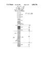
- FIG. 1 shows a schematic of a typical injection well 10 for in situ combustion enhanced oil recovery.
- all the below ground 12 tubulars such as surface casing 14 (which extends above ground), casing 16, and tubing 18, for example, are carbon steel
- the packer 22, used to isolate the annulus 28 from injection region 30 and from hydrocarbon-containing formation 26, is also commonly comprised of carbon steel and has elastomeric seals 20.
- Techniques used to mitigate the problem of injection well fires by protecting well equipment from damage include (1) use of alloys for fabrication of the tubulars and packer;(2) "fail safe” inert gas or water dump systems, including down hole temperature measurement devices connected with the inert gas or water dump system;(3) use of down-hole temperature measurement as part of a shut off system for the oxygen-containing injection gas; and (4) combinations of these techniques.
- alloys such as Incoloy 825 and Monel which are used to replace carbon steel is about 20 to 40 times the cost equivalent of the carbon steel. Even when alloy use is restricted to lower casing 24, packer 22 and other equipment below packer 22, the use of alloy material increases well costs over the range of about $10,000 to $50,000 per well. In addition, the use of alloys does not prevent overheating of the packer 22 in the event of a well fire, and such heating can cause a change in the properties of the elastomeric seal 20, and loss of the seal between the annulus 28 and injection region 30 of the well.
- a method and means for passive protection of wellbore structures and the equipment used therein is provided in the form of a specialized packing system which is placed in the wellbore below ground level, and preferably below the packer.
- the packing particle size is a critical feature of the invention. Particle size distribution and packing placement within the wellbore as a function of particle size are additional features of the invention which can be tailored to the application.
- the packing material can be any non combustible material, although non-combustible materials which change in chemical or physical structure in a manner which consumes heat (which are endothermic) are preferred.
- the size of the packing should be sufficiently large that the packing has a reasonably small impact on the pressure required to inject fluids into the formation (in the case of an injection well) or a reasonably small impact on the pressure of fluid hydrocarbons entering a well (in the case of a production well). At the same time, the size of the packing must be sufficiently small to provide adequate heat transfer surface per volume of packing, to provide the quenching action desired in the case of a well fire.
- W weight of casing (lb. steel/ft.)
- a design factor based on the safety factor required.
- the range of a was empirically determined, and is from at least about 0.001 to about 1.0.
- a minimum spherical diameter of about 0.08 inches is preferred, to avoid packings that result in unacceptable pressure gradients.
- V p volume of the non-spherical particle (in. 3 )
- the particle size distribution is limited to consist essentially of particles having a largest particle volume which is less than about 6 times the volume of the smallest particle.
- the preferred particle size distribution consists essentially of particles having a largest particle volume which is less than about 1.5 times the volume of the smallest particle.
- the placement of packing in the well can be at locations from just below ground level to the very bottom of the wellbore (the rat hole).
- the following zones within the subterranean well are identified relative to the present invention, in descending order within the well: a free zone, a packer protection zone, a casing quench zone, a pay or formation zone, and a rat hole.
- the length of each zone and the point within the wellbore at which the zones begin depend on the well design.
- the free zone begins below the packer and extends the distance from the bottom of the packer to the top of the packing.
- the free zone can be any length and may not exist in some applications.
- the packer protection zone extends from the top of the packing down to the casing quench zone, and is designed to prevent heat of combustion from migrating to the packer.
- the packer protection zone is typically at least 10 ft. in length.
- the casing quench zone extends from the bottom of the packer protection zone downward to the upper portion of the pay zone or formation zone, and provides protection from propagation of a casing fire above the pay zone.
- a typical casing quench zone ranges from about 2 ft to about 100 ft. in length.
- the length of the pay zone or formation zone depends on the geological formation in general, and the rat hole is minimal in size as necessitated by well mechanics (a typical rat hole length ranges between about 5 ft. and about 30 ft).
- the packing material particle size was empirically determined to be capable of extinguishing carbon steel fires in a simulated injection well.
- a high pressure, high purity oxygen atmosphere was used in contact with the inside volume of a simulated wellbore to evaluate the ability of different packing systems to quench carbon steel casing fires.
- FIG. 1 shows a typical injection well 10 of the type well known in the art, including surface casing 14, casing 16, tubing 18, seals 20, packer 22, lower casing 24, pay or formation zone 26, and rat hole 32.
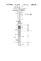
- FIG. 2A shows a similar injection well 200 which includes the packing structure of the present invention.
- the zones shown in FIG. 2A include a free zone 114, which begins directly beneath packer 110, which free zone in followed in descending order within the well by packer protection zone 124, casing quench zone 126, pay or formation zone 128, and rat hole zone 130.
- FIG. 2B shows a production well 201 in a manner similar to the injection well shown in FIG. 2A, wherein the packed zones are essentially the same, and wherein the production well includes a pump 138, a sucker tube 140, and valving arrangements above ground which differ from those of the injection well.
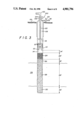
- FIG. 3 shows an injection well 300 modified to have an "open hole" completion. There is no casing surrounding pay zone 128 which is bordered by formation 134.
- FIG. 4 shows an injection well 400 wherein packer 110 (as shown in FIG. 2A) has bee eliminated and replaced with packing.
- FIG. 5 shows an injection well 500 wherein a conduit 144 which may be screen-like in construction is used to replace a portion of the packing in pay zone 128.
- FIG. 6 shows an injection well 600 wherein the packing particle size diameter has been altered in a central core area 148 above zone 130, to reduce pressure drop.
- the particle size diameter in central core 148 typically is somewhat larger than that used in zone 128.
- FIG. 7 depicts an injection well 700 which comprises multiple injection strings.
- the present invention pertains to packing which can be used in injection wellbores in general, and in some production wellbores, for the recovery of hydrocarbons.
- the packing particle size and distribution and the packing placement within the wellbore are the principal features of the preferred embodiment of this invention.
- FIGS. 2A and 2B show the general embodiment of the invention for injection and production wells, respectively, which have packing only below packer 110. Although, packing can be used at any position within the well below ground level, the preferred use of packing is below packer 110.
- the free zone 114 provides space for the expansion and contraction of the layers of packing within the well casing below packer 110. Even if no free zone 114 is planned, one will form over time due to settling of the particles.
- the free zone length is not of critical importance to the design of the packing system of the present invention.
- the packer protection zone 124 is designed as a heat sink to control the amount of heat transfer to packer 110.
- packer protection zone 124 ranges from about 10 to about 50 feet in length for heavy oil recovery applications.
- the casing quench zone 126 is designed to prevent carbon steel casing fires from propagating up the well.
- casing quench zone 126' ranges from about 10 feet to about 25 feet in length for the heavy oil recovery applications.
- the pay zone 128 extends the length of the hydrocarbon bearing zone, and the purpose of the packing in zone 128 is to reduce available space for hydrocarbon accumulation within the well and to provide a heat sink which prevents ignition of the well casing.
- a secondary function of the packing in pay zone 128 is to support overlaying packing.
- the rat hole 130 is designed to collect debris which enters wellbore. Rat holes are particularly useful in heavy oil production wells where the debris tends to settle to the bottom of the bore. Although rat holes are frequently present in injection wells, it is possible to have an injection well which does not utilize a rat hole.
- the size of packing particles in each zone is designed within a range which provides empirically determined fire quench protection for the well equipment.
- the particle diameter in packer protection zone 124 should provide a good heat sink while simultaneously maintaining a low pressure drop in fluids flowing through this area. Since pressure drop is the controlling feature at this zone, the largest particle size packing is placed at this location within the well.
- the particle diameter in casing quench zone 126 is the smallest diameter packing within the portion of the wellbore which functions as the passive protection system for well components in case of fire (excluding the rat hole).
- the smaller particles provide increased surface area per packing volume, and thus faster heat transfer to the packing when needed to quench a well casing fire. Since manly gases are flowing through an injection well or a gas production well, the pressure drop effect of the smaller particles in casing quench zone 126 can be tolerated in these wells better than in an oil production well, where the particles in zone 126 may have to be slightly larger by comparison. In the case of a light oil production well, it is likely the particle size in quench zone 126 will be about the same size as that in packer protection zone 124. The length of the casing quench zone is a tradeoff between allowable pressure drop and the desired level of protection.
- the particle size of the packing in pay zone 128 for an injection well or gas well is likely to be intermediate between the particle size of packer protection zone 124 and casing quench zone 126. There is competition between the desire to have a smaller particle size and good heat transfer to stop the fire at the formation level and the desire to have the lower pressure drop which is inherent in a larger particle size. In formation zone 128 there is the additional consideration that the particle size should be either at least 10% smaller than or 10% larger than the diameter of perforations 132 in the well shaft, to prevent blocking of fluid flow to (injection well) or from (production well) the formation. In the most preferred embodiments for an injection well or gas well, the packing particle size in rat hole 130 is the smallest in the well, because it is desired to minimize the volume available for hydrocarbon occupancy. There is no pressure drop problem created by the small particle size, since fluid flow down from the injection well or up through the production well does not pass through rat hole 130. However, the size of rat hole packing is not a critical feature of the present invention.
- the packing is comprised of materials which are non-combustible for the environment being considered.
- carbon steel or stainless steel as well as ceramic, gravel, sand, glass beads, limestone (calcium carbonate) and other similar materials can be used as packinq.
- carbon steel, stainless steel, and other similar materials should not be used for packing because they can burn.
- preferred packing materials include ceramics, gravel, sand, glass beads limestone, and other materials which tend to be non-combustible in the environment.
- Some types of packing material are endothermic (react in the environment to consume heat), and such materials are particularly useful. Examples of these materials include limestone (which not only uses heat to liberate carbon dioxide, but the carbon dioxide acts to quench combustion); perlite, which can comprise water which can be liberated and then vaporized. These endothermic materials provide an increased heat sink over that provided by materials which simply consume heat in the form of an increase in mass temperature.
- packing materials which are able to withstand either the acid or caustic washings which are used to remove foreign materials or build up of chemical materials which tend to plug flow paths.
- the packing should also be able to be removed from the well by commonly used oil field procedures such as water recirculation.
- FIG. 2A shows a schematic of an injection well which serves as reference.
- injection gas containing a fraction of oxygen added for enhancement is introduced into injection well 200 through conduit 102.
- the gas flows through valves 104 and 106 into conduit 108 which transfers the gas through packer 110 and conduit 112 to free zone 114.
- Packer 110 seals off annulus region 116 from free zone 114.
- Annulus region 116 is typically filled with water, air, or an inert gas which is introduced through conduit 118 via valve 120.
- Region 116 is maintained at a hiqher pressure than the pressure within conduit 108 to ensure that in the event a leak develops, flow will be from region 116 into region 122 within conduit 108.
- the water, nitrogen or other inert gas typically contained in region 116 is used to provide a quench medium for zones 114 through 130 in the event of a well fire.
- the volume of the largest size ball is less than about 1.5 times the volume of the smallest ball (the most preferred particle distribution).
- Casing quench zone 126' is about 10 ft. in length.
- the aluminum oxide balls in pay zone 128 are about 10 percent smaller in diameter than the diameter of perforations 132 in the well shaft walls.
- the gas flows through perforations 132 into formation 134, where the gas is used to sustain combustion of the fire front.
- the rat hole 130 beneath pay zone 128 contains aluminum oxide spheres having a diameter of about 0.08 in.
- zones 124 through 128, the packing provides a heat sink as well as a reduction in free volume which otherwise could be occupied by hydrocarbon containing liquids and gases. Consequently, if temperatures in these zones reach the ignition temperature of the hydrocarbons, the temperatures experienced by the casing will be lower due to heat absorption of the packing, and the combustion period, if any, will be short due to the limited quantity of fuel available.
- the pay zone 128 and rat hole 130 are the most likely locations for injection well fires because of the near proximity of hydrocarbon in the formation and the potential for hydrocarbons to backflow into the injection well due to gravity effects. If a fire starts in these zones in an unpacked well, large quantities of fuel may be available to heat the casing materials to temperatures beyond which they lose their structural characteristics. In the case of oxygen enriched air in situ combustion, the casings may begin to burn. The heat of combustion will eventually raise the temperature of the seals in packer 110, which will release the inert fluid contained in region 116 to quench combustion. However, significant damage occurs and repair costs are incurred in putting the well back into service.
- Packing zones 128 and 130 with the aluminum oxide balls reduces the volume of fuel these regions can hold by about 50 percent to about 75 percent.
- the heat capacity and thermal conductivity of the aluminum oxide spheres reduces the maximum temperature experienced within the well and thus the temperature experienced by casing 136.
- the migration of heat to packer 110 is substantially slowed, and the relatively low temperature and heat capacity of the injection gases flowing into the well shaft provides cooling in packer protection zone 124 and in casing quench zone 126.
- the smaller aluminum oxide spheres in casing quench zone 126 provide additional surface contact with casing 136 at the level of quench zone 126 to more effectively quench the burning at that level, reducing the amount of injection well tubulars damaged by the fire.
- the packing in pay zone 128 provides a heat sink to absorb much of the heat transferred from outside the well to casing walls 136. If the temperatures rise high enough for ignition of the casing 136 at pay zone 128, the packing in casing quench zone 126 is frequently adequate to quench combustion of casing 136 above formation level 134.
- Injection Pressure for an empty well is about 1,500 psia.
- a suitable packing comprises:
- the increase in pressure drop across the well due to the presence of the packing is about 45 psia, compared with a total injection pressure requirement of about 1,545 psia.
- Example 2 The pressure drops provided in Example 2 were calculated using models developed for flow through packed towers and porous media. The calculated pressure drop represents only about a 0.5 percent increase in compression power when compared with an unpacked well.
- the packing described above can also be used for gas production wells due to the low pressure drop experienced across the packing, and can be used for light oil production wells; although the pressure drop across a light oil production well will be considerably higher.
- the preferred packing comprises more than one particle size diameter. This example provides a listing of well parameters and the recommended packing for an injection well when more than one packing particle size is used.
- Injection Pressure for an empty well is about 1,500 psia.
- a preferred packing comprises:
- the increase in pressure drop across the well due to the packing is about 30 psia, compared with a total injection pressure requirement of about 1,530 psia.
- Example 3 The pressure drops provided in Example 3 were calculated using models developed for flow through packed towers and porous media. The calculated pressure drop increase represents only about a 0.5 percent increase in compression power when compared with an unpacked well.
- FIG. 3 shows a preferred embodiment 300 in which an "open hole" completion is used; there is no casing surrounding zones 128 and 130.
- the packing provides structural support to the formation as well as protection for casing 142 (and indirectly for packer 110). Packing in zones 128 and 130 only may be larger than defined by the packing size diameter equation when the open hole completion is used.
- the bore hole in zone 128 may be reamed out to larger diameters to improve injectivity or productivity depending on whether the well is an injection or a production well.
- casing 142 may be 7 inches in diameter and the bore hole in zone 128 may be underreamed to 2 feet in diameter.
- FIG. 4 Another preferred embodiment of the well packing of the present invention is shown in FIG. 4.
- An injection well 400 is depicted in which the packer (110 in FIG. 3) has been replaced with packing 146 to control potential combustion in the packer protection zone 124.
- Packer protection zone 124 has been expanded toward ground level 119, terminating at free zone 114 which extends from slightly below ground level 119 to packer protection zone 124. Since the tubulars for injection now extend beneath the packing, it is necessary to place a screen or slotted cover 152 at the end of the tubular to prevent packing from entering the opening to the tubular.
- FIG. 5 shows an injection well 500 in which a portion of the packing in the center of the packing structure of pay zone 128 has been replaced by space holding structure 144 which may be constructed of a screen like material or a slotted liner wrapped in wire or similar construction which aids in reducing the pressure drop in the area of pay zone 128. Screened or slotted covers 154 are used at the open ends of space holding structure 144 to prevent packing from entering the openings.
- space holding structure 144 may be constructed of a screen like material or a slotted liner wrapped in wire or similar construction which aids in reducing the pressure drop in the area of pay zone 128.
- Screened or slotted covers 154 are used at the open ends of space holding structure 144 to prevent packing from entering the openings.
- injection well 600 packing is comprised of a central core of packing 148 which has an effective diameter which is typically greater than the diameter of packing in pay zone 128.
- the larger effective diameter packing in central core 148 acts to reduce the overall pressure drop induced by the packing.
- Central core packing 148 can extend the entire length of the packed zones above the rat hole, as shown in FIG. 6, or can be used in a particular zone only, such as pay zone 128.
- FIG. 7 shows injection well 700 which comprises multiple injection strings 122 and 123.
- the tubulars below packer 110 can be filled with packing or can be devoid of packing, in which case a screen or similar device is used at the bottom of the tubular to prevent packing from entering the tubular.
- the packing systems described herein provide significant advantages over alternative means of protecting wells from fire damage.
- the use of packing permits the safe use of carbon steel casing, significantly reducing the costs of installing and maintaining a well.
- the cost of packing materials is relatively low.
- the packing system is much simpler, less costly, and more reliable than the use of a temperature sensing device in combination with a flood/quench technique.
- use of the packing system in injection wells would permit initiation of combustion using gases have the desired oxygen concentration without the necessity of using more expensive techniques in which air is used to initiate combustion, followed by blend-up to design purity.
Abstract
Description
______________________________________
Zone                    "a" Range
______________________________________
The free zone contains no packing.
Packer Protection       0.001-.05
Casing Quench           0.3-1.0
Pay or Formation Zone   0.05-.1
______________________________________
 The rat hole "a" is such that D.sub.p > 0.08 in. for the Rat Hole.
______________________________________
                     Maximum*
                             Selected
     "a"     Length  Diameter
                             Diameter
                                     Pressure Drop
Zone Value   (ft.)   (in.)   (in.)   Increase (psi)
______________________________________
124  .001    50      .52     .19     20
126  .001    10      .52     .19      5
128  .001    20      .52     .19     20
130  .001    10      .52     .19     --
______________________________________
______________________________________
                     Maximum*
                             Selected
     "a"     Length  Diameter
                             Diameter
                                     Pressure Drop
Zone Value   (ft.)   (in.)   (in.)   Increase (psi)
______________________________________
124  0.001   50      .52     .44      5
126  0.3     10      .26     .19      5
128  0.05    20      .48     .19     20
130  0.5     10      .08     .08     --
______________________________________
 *Maximum diameter using the packing particle diameter equation.
Claims (14)
Priority Applications (2)
| Application Number | Priority Date | Filing Date | Title |
|---|---|---|---|
| US07/286,174 US4901796A (en) | 1988-12-19 | 1988-12-19 | Well packing system |
| CA002005806A CA2005806C (en) | 1988-12-19 | 1989-12-18 | Well packing system |
Applications Claiming Priority (1)
| Application Number | Priority Date | Filing Date | Title |
|---|---|---|---|
| US07/286,174 US4901796A (en) | 1988-12-19 | 1988-12-19 | Well packing system |
Publications (1)
| Publication Number | Publication Date |
|---|---|
| US4901796A true US4901796A (en) | 1990-02-20 |
Family
ID=23097417
Family Applications (1)
| Application Number | Title | Priority Date | Filing Date |
|---|---|---|---|
| US07/286,174 Expired - Fee Related US4901796A (en) | 1988-12-19 | 1988-12-19 | Well packing system |
Country Status (2)
| Country | Link |
|---|---|
| US (1) | US4901796A (en) |
| CA (1) | CA2005806C (en) |
Cited By (10)
| Publication number | Priority date | Publication date | Assignee | Title |
|---|---|---|---|---|
| US5115866A (en) * | 1991-01-18 | 1992-05-26 | K N Energy, Inc. | Soil vapor well construction |
| US5266291A (en) * | 1992-05-05 | 1993-11-30 | Praxair Technology, Inc. | Packed bed arrangement for oxidation reaction system |
| US5360067A (en) * | 1993-05-17 | 1994-11-01 | Meo Iii Dominic | Vapor-extraction system for removing hydrocarbons from soil |
| US5360603A (en) * | 1993-08-23 | 1994-11-01 | Praxair Technology, Inc. | Packed bed arrangement useful for mixing and/or oxidation |
| US5492178A (en) * | 1993-11-12 | 1996-02-20 | Halliburton Company | Well treating methods and devices using particulate blends |
| WO2003067026A1 (en) * | 2002-02-06 | 2003-08-14 | Santos Ltd | Gas well packing system |
| US6786285B2 (en) | 2001-06-12 | 2004-09-07 | Schlumberger Technology Corporation | Flow control regulation method and apparatus |
| US6857475B2 (en) | 2001-10-09 | 2005-02-22 | Schlumberger Technology Corporation | Apparatus and methods for flow control gravel pack |
| US20060027377A1 (en) * | 2004-08-04 | 2006-02-09 | Schlumberger Technology Corporation | Well Fluid Control |
| US10302089B2 (en) | 2015-04-21 | 2019-05-28 | Baker Hughes, A Ge Company, Llc | Circulation pump for cooling mechanical face seal of submersible well pump assembly |
Citations (3)
| Publication number | Priority date | Publication date | Assignee | Title |
|---|---|---|---|---|
| US3456735A (en) * | 1967-02-01 | 1969-07-22 | Exxon Production Research Co | Method for completing wells to prevent paraffin deposits |
| US4008763A (en) * | 1976-05-20 | 1977-02-22 | Atlantic Richfield Company | Well treatment method |
| US4623021A (en) * | 1984-11-14 | 1986-11-18 | Mobil Oil Corporation | Hydraulic fracturing method employing a fines control technique |
-
1988
- 1988-12-19 US US07/286,174 patent/US4901796A/en not_active Expired - Fee Related
-
1989
- 1989-12-18 CA CA002005806A patent/CA2005806C/en not_active Expired - Fee Related
Patent Citations (3)
| Publication number | Priority date | Publication date | Assignee | Title |
|---|---|---|---|---|
| US3456735A (en) * | 1967-02-01 | 1969-07-22 | Exxon Production Research Co | Method for completing wells to prevent paraffin deposits |
| US4008763A (en) * | 1976-05-20 | 1977-02-22 | Atlantic Richfield Company | Well treatment method |
| US4623021A (en) * | 1984-11-14 | 1986-11-18 | Mobil Oil Corporation | Hydraulic fracturing method employing a fines control technique |
Cited By (11)
| Publication number | Priority date | Publication date | Assignee | Title |
|---|---|---|---|---|
| US5115866A (en) * | 1991-01-18 | 1992-05-26 | K N Energy, Inc. | Soil vapor well construction |
| US5266291A (en) * | 1992-05-05 | 1993-11-30 | Praxair Technology, Inc. | Packed bed arrangement for oxidation reaction system |
| US5360067A (en) * | 1993-05-17 | 1994-11-01 | Meo Iii Dominic | Vapor-extraction system for removing hydrocarbons from soil |
| US5360603A (en) * | 1993-08-23 | 1994-11-01 | Praxair Technology, Inc. | Packed bed arrangement useful for mixing and/or oxidation |
| US5492178A (en) * | 1993-11-12 | 1996-02-20 | Halliburton Company | Well treating methods and devices using particulate blends |
| US6786285B2 (en) | 2001-06-12 | 2004-09-07 | Schlumberger Technology Corporation | Flow control regulation method and apparatus |
| US6857475B2 (en) | 2001-10-09 | 2005-02-22 | Schlumberger Technology Corporation | Apparatus and methods for flow control gravel pack |
| WO2003067026A1 (en) * | 2002-02-06 | 2003-08-14 | Santos Ltd | Gas well packing system |
| US20060027377A1 (en) * | 2004-08-04 | 2006-02-09 | Schlumberger Technology Corporation | Well Fluid Control |
| US7240739B2 (en) | 2004-08-04 | 2007-07-10 | Schlumberger Technology Corporation | Well fluid control |
| US10302089B2 (en) | 2015-04-21 | 2019-05-28 | Baker Hughes, A Ge Company, Llc | Circulation pump for cooling mechanical face seal of submersible well pump assembly |
Also Published As
| Publication number | Publication date |
|---|---|
| CA2005806C (en) | 1994-05-24 |
| CA2005806A1 (en) | 1990-06-19 |
Similar Documents
| Publication | Publication Date | Title |
|---|---|---|
| US7640965B2 (en) | Creating a well abandonment plug | |
| US5411089A (en) | Heat injection process | |
| CA2690105C (en) | Apparatus and method for downhole steam generation and enhanced oil recovery | |
| CA2537930C (en) | Production of natural gas from hydrates | |
| US20090101344A1 (en) | Water Dissolvable Released Material Used as Inflow Control Device | |
| AU2002346437A1 (en) | In-situ casting of well equipment | |
| US4901796A (en) | Well packing system | |
| US4019578A (en) | Recovery of petroleum from tar and heavy oil sands | |
| US3993135A (en) | Thermal process for recovering viscous petroleum | |
| US4645003A (en) | Patterns of horizontal and vertical wells for improving oil recovery efficiency | |
| US9115579B2 (en) | Apparatus and method for downhole steam generation and enhanced oil recovery | |
| Gillham et al. | Low cost IOR: an update on the W. Hackberry air injection project | |
| US2913050A (en) | Preventing explosions in bore holes during underground combustion operations for oil recovery | |
| US3280911A (en) | Well liner with permeable joint | |
| Gates et al. | Combustion as a primary recovery process-Midway Sunset field | |
| US3160208A (en) | Production well assembly for in situ combustion | |
| US6419018B1 (en) | Subterranean well completion apparatus with flow assurance system and associated methods | |
| US3414055A (en) | Formation consolidation using a combustible liner | |
| US3343598A (en) | Protection of production well equipment in in situ combustion operation | |
| US7066252B2 (en) | Erosion resistant, self and/or artificial external cleaning solid exclusion system | |
| US3223165A (en) | Method for heating or igniting well formations with pyrophoric materials | |
| US3087545A (en) | Method of heating and producing oil wells | |
| Milhem et al. | Performance of a pilot cyclic steam stimulation project in Kuwait | |
| US3072191A (en) | Heat transfer petroleum recovery process | |
| CA1214989A (en) | Steam ignition and control of an oxygen-driven fire flood injection well |
Legal Events
| Date | Code | Title | Description |
|---|---|---|---|
| AS | Assignment |
Owner name: UNION CARBIDE CORPORATION, CONNECTICUT Free format text: ASSIGNMENT OF ASSIGNORS INTEREST.;ASSIGNOR:DRNEVICH, RAYMOND F.;REEL/FRAME:005137/0646 Effective date: 19881214 |
|
| FEPP | Fee payment procedure |
Free format text: PAYOR NUMBER ASSIGNED (ORIGINAL EVENT CODE: ASPN); ENTITY STATUS OF PATENT OWNER: LARGE ENTITY |
|
| AS | Assignment |
Owner name: UNION CARBIDE INDUSTRIAL GASES TECHNOLOGY CORPORAT Free format text: ASSIGNMENT OF ASSIGNORS INTEREST.;ASSIGNOR:UNION CARBIDE INDUSTRIAL GASES INC., A CORP. OF DE;REEL/FRAME:005206/0425 Effective date: 19891220 |
|
| CC | Certificate of correction | ||
| AS | Assignment |
Owner name: PRAXAIR TECHNOLOGY, INC., CONNECTICUT Free format text: CHANGE OF NAME;ASSIGNOR:UNION CARBIDE INDUSTRIAL GASES TECHNOLOGY CORPORATION;REEL/FRAME:006337/0037 Effective date: 19920611 |
|
| FEPP | Fee payment procedure |
Free format text: PAYER NUMBER DE-ASSIGNED (ORIGINAL EVENT CODE: RMPN); ENTITY STATUS OF PATENT OWNER: LARGE ENTITY Free format text: PAYOR NUMBER ASSIGNED (ORIGINAL EVENT CODE: ASPN); ENTITY STATUS OF PATENT OWNER: LARGE ENTITY |
|
| FPAY | Fee payment |
Year of fee payment: 4 |
|
| FEPP | Fee payment procedure |
Free format text: PAYER NUMBER DE-ASSIGNED (ORIGINAL EVENT CODE: RMPN); ENTITY STATUS OF PATENT OWNER: LARGE ENTITY Free format text: PAYOR NUMBER ASSIGNED (ORIGINAL EVENT CODE: ASPN); ENTITY STATUS OF PATENT OWNER: LARGE ENTITY |
|
| REMI | Maintenance fee reminder mailed | ||
| LAPS | Lapse for failure to pay maintenance fees | ||
| FP | Lapsed due to failure to pay maintenance fee |
Effective date: 19980225 |
|
| STCH | Information on status: patent discontinuation |
Free format text: PATENT EXPIRED DUE TO NONPAYMENT OF MAINTENANCE FEES UNDER 37 CFR 1.362 |