US4399736A - Vacuum suspended brake booster control valve - Google Patents
Vacuum suspended brake booster control valve Download PDFInfo
- Publication number
- US4399736A US4399736A US06/237,528 US23752881A US4399736A US 4399736 A US4399736 A US 4399736A US 23752881 A US23752881 A US 23752881A US 4399736 A US4399736 A US 4399736A
- Authority
- US
- United States
- Prior art keywords
- control valve
- valve
- annular
- vacuum
- valve seat
- Prior art date
- Legal status (The legal status is an assumption and is not a legal conclusion. Google has not performed a legal analysis and makes no representation as to the accuracy of the status listed.)
- Expired - Lifetime
Links
Images
Classifications
-
- B—PERFORMING OPERATIONS; TRANSPORTING
- B60—VEHICLES IN GENERAL
- B60T—VEHICLE BRAKE CONTROL SYSTEMS OR PARTS THEREOF; BRAKE CONTROL SYSTEMS OR PARTS THEREOF, IN GENERAL; ARRANGEMENT OF BRAKING ELEMENTS ON VEHICLES IN GENERAL; PORTABLE DEVICES FOR PREVENTING UNWANTED MOVEMENT OF VEHICLES; VEHICLE MODIFICATIONS TO FACILITATE COOLING OF BRAKES
- B60T13/00—Transmitting braking action from initiating means to ultimate brake actuator with power assistance or drive; Brake systems incorporating such transmitting means, e.g. air-pressure brake systems
- B60T13/10—Transmitting braking action from initiating means to ultimate brake actuator with power assistance or drive; Brake systems incorporating such transmitting means, e.g. air-pressure brake systems with fluid assistance, drive, or release
- B60T13/24—Transmitting braking action from initiating means to ultimate brake actuator with power assistance or drive; Brake systems incorporating such transmitting means, e.g. air-pressure brake systems with fluid assistance, drive, or release the fluid being gaseous
- B60T13/46—Vacuum systems
- B60T13/52—Vacuum systems indirect, i.e. vacuum booster units
- B60T13/57—Vacuum systems indirect, i.e. vacuum booster units characterised by constructional features of control valves
-
- Y—GENERAL TAGGING OF NEW TECHNOLOGICAL DEVELOPMENTS; GENERAL TAGGING OF CROSS-SECTIONAL TECHNOLOGIES SPANNING OVER SEVERAL SECTIONS OF THE IPC; TECHNICAL SUBJECTS COVERED BY FORMER USPC CROSS-REFERENCE ART COLLECTIONS [XRACs] AND DIGESTS
- Y10—TECHNICAL SUBJECTS COVERED BY FORMER USPC
- Y10T—TECHNICAL SUBJECTS COVERED BY FORMER US CLASSIFICATION
- Y10T137/00—Fluid handling
- Y10T137/8593—Systems
- Y10T137/86919—Sequentially closing and opening alternately seating flow controllers
Definitions
- the invention relates to a control valve arrangement for a vacuum suspended brake booster, and more particularly to one which provides improved sealing of the vacuum and air valves with the floating control valve under conditions of rest, poise and booster actuation.
- a linearly movable air valve seat connected to be moved by an input push rod.
- the valve seat is made as part of a piston-like element slidable in a power wall piston and arranged generally concentrically within the vacuum valve seat formed as a part of the piston.
- a floating control valve is mounted so as to be able to move linearly relative to the air valve seat and the vacuum valve seat under various conditions of operation and to engage either or both of those valve seats depending upon the particular condition of operation required.
- the air valve seat At rest the air valve seat is in sealing contact with the floating control valve and seals the variable pressure chamber against entry of atmospheric air.
- the vacuum valve seat is not in engagement with the floating control valve so that vacuum from the vacuum pressure chamber is also found in the variable pressure chamber of the booster.
- the air valve During initial booster actuation the air valve is pushed forward and the floating control valve moves with it until it contacts the vacuum valve seat on the power piston. This position is referred to as the poise position. Additional forward movement of the air valve opens the air valve seat relative to the floating control valve and allows atmospheric air to enter the booster variable pressure chamber, setting up a pressure differential across the booster power wall to actuate the booster.
- the vacuum valve seat When the booster is actuated to the desired extent, the vacuum valve seat has moved forward to such an extent that the floating control valve again engages the air valve seat, thus establishing the valve in the poise position.
- This valve position will exist when the vehicle operator is exerting a steady force on the brake pedal with his foot to maintain a constant brake pressure.
- the air valve may be moved forwardly to obtain additional brake pressure to such an extent that full atmospheric air pressure is obtained in the variable pressure chamber and the booster has been actuated to its maximum extent. This condition is known as runout.
- the modified valve arrangement has a floating control valve body including a rubber ring molded around a stiff insert which provides stiffening of the air valve seating area and controlled flexibility for the outer portion of the floating control valve. This is accomplished by a reduced outer diameter insert which does not extend radially outwardly to the effective diameter of the vacuum valve seat.
- the flexibility is also controlled as needed by providing a recess or undercut in the floating control valve rubber body to provide improved sealability at poise and runout positions.
- Another feature of the invention is the relocation of the air valve spring from the forward side of the air valve body to the input push rod so that the air valve spring pulls on the air valve body.
- the ball-and-socket connection between the air valve body and the push rod allows the air valve body to seek its own plane.
- the floating control valve spring is applied directly against the insert in the floating control valve body rather than through the rubber, thereby contributing to a more even loading of the floating control valve by the force of the valve spring, further contributing to more positive sealing under various conditions of operation.
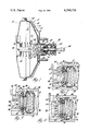
- FIG. 1 is a cross section view of a vacuum suspended brake booster having the control valve arrangement embodying the invention incorporated therein.
- FIG. 2 is an enlarged cross section view of the control valve arrangement embodying the invention and particularly illustrates the valve arrangement in the poise position.
- FIG. 3 is a cross section view of the control valve arrangement similar to FIG. 2 and illustrates the valve arrangement in the booster actuating or runout position.
- FIG. 4 is a cross section view of the control valve arrangement similar to FIG. 2 and illustrates the valve arrangement in the rest position.
- the vacuum suspended brake booster 10 includes a housing 12 divided by a power wall 14 into a vacuum pressure chamber 16 and a variable pressure chamber 18.
- a suitable connection not shown, communicates engine intake manifold vacuum into chamber 16.
- the power wall 14 includes a piston 20 on which a diaphragm 22 is suitably secured.
- a diaphragm support member 24 is also secured to piston 20.
- the diaphragm outer diameter 26 is secured to the outer peripheral portions of the walls forming housing 12.
- Piston 20 is sealingly and reciprocably mounted within housing 12 and has a rearward extension 28 which passes through a seal 30 and a housing rearward extension 32.
- the forward end of piston 20 has a reaction mechanism 34 and an output rod 36.
- Rod 36 extends through a seal 38 in the forward wall of housing 12 and is arranged to actuate a master cylinder, not shown.
- the piston return spring 40 is located in vacuum pressure chamber 16 and urges the piston 20 rearwardly.
- the control valve assembly 42 is contained within the piston rearward extension 28. It includes the air valve body 44 which is reciprocably mounted within piston extension 28 and has the annular air valve seat 46 formed thereon.
- the vacuum valve seat 48 is formed as a part of the piston extension 28, is annular, and is positioned generally concentrically outward of the air valve seat 46.
- the floating control valve body 50 includes a mounting ring 52 by which the valve body is mounted within piston extension 28.
- a diaphragm-like flexible connection 54 connects mounting ring 52 to the valve ring 56.
- the valve ring is positioned in axial alignment with the air valve seat 46 and the vacuum valve seat 48 and is axially movable within the piston extension 28.
- the valve ring has an outer portion 58 providing a valve face surface 60 aligned for sealing engagement and disengagement with the vacuum valve seat 48.
- the valve ring 56 has a ring inner portion 62 provided with a valve face surface 64 which is aligned axially with the air valve seat 46 for sealing engagement and disengagement.
- a stiff annular ring 66 is molded in the valve ring inner portion 62 so that its outer periphery 68 does not extend radially outward to the ring outer portion 58, and is therefore radially inward of the vacuum valve seat 48.
- Ring 66 is in axial alignment with the air valve seat 46 back of valve face surface 64, and also extends radially inward beyond the inner surface of the valve ring 56 so as to act as a spring seat for one end of the floating control valve spring 70.
- a spring cup 72 is secured to the valve body mounting ring 52 on the inner side thereof and has a rearwardly positioned radially inwardly extending flange 74 which acts as a seat for the other end of spring 70.
- spring 70 continually urges the valve ring 56 toward the air valve seat 46 and vacuum valve seat 48 relative to the mounting ring 52 and piston extension 28.
- the flexible connection 54 permits movement of the valve ring 56 relative to the mounting ring 52.
- the valve ring 56 is also provided with an annular recess or undercut 76 located between the valve ring outer portion 58 and inner portion 62 so as to provide controlled flexibility to the outer portion.
- the recess may be provided on the rear side of the valve ring 56, as illustrated, or in some arrangements may be provided on the front side.
- the air valve spring 78 is positioned rearwardly of flange 74 of spring cup 72.
- the input push rod 80 is operatively attached at its rearward end for brake pedal operation in a manner well known in the art and not further illustrated.
- Rod 80 extends through the spring 78, the cup 72, the spring 70, and the valve body 50. Its forward end terminates in a ball-and-socket joint within the air valve body 44. This joint is such that force may be transferred between the push rod 80 and the air valve body 44 in either direction.
- a flange 82 formed on the push rod 80 acts as a spring seat for air valve spring 78.
- Spring 78 is under compression so that it urges the input push rod 80 rearwardly, exerting a pulling force on the air valve body 44.
- the ball-and-socket arrangement between the air valve body 44 and the push rod 80 allows the air valve body to seek its own plane and effectively prevents a cocking action of the valve body within the piston extension 28.
- a suitable air filter 84 and boot 86 are provided at the rear portion of the booster assembly so that atmospheric air entering the booster is relatively clean and the valve elements are protected.
- the control valve assembly 42 When the booster assembly of FIG. 1 is at rest, the control valve assembly 42 is in the position shown in FIG. 4. In this arrangement the air valve body 44 is positioned rearwardly so that the air valve seat 46 is in sealing engagement with the valve face surface 64.
- the air valve spring 78 is sufficiently stronger than the floating control valve spring 70 so as to exert a force through the air valve body 44 and the floating control valve body 50, tending to further compress spring 70. This has provided sufficient rearward movement of the floating control valve body 50 to disengage the valve face surface 60 from the vacuum valve seat 48. This opens the connection by way of power piston passages 88 and 90 between the vacuum pressure chamber 16 and the variable pressure chamber 18, while preventing atmospheric air from passing the air valve seat 46. Thus vacuum pressure is found in both chambers 16 and 18.
- vacuum valve seat 48 moves with it and the floating control valve 50 follows until the poise position of FIG. 2 is once again obtained.
- the vehicle operator may hold the brakes in the applied position with a substantially constant brake application force by holding the control valve assembly 42 in the poise position. If he requires the maximum amount of braking force, he may move the air valve body 44 forward to such an extent that full atmospheric air pressure is exerted in chamber 18 with the air valve seat 46 remaining disengaged from the valve face surface 64. This is the runout position also illustrated in FIG. 3.
- the air valve spring 78 Upon release of the brake pedal by the vehicle operator, the air valve spring 78 will move the push rod 80 and the air valve body 44 rearwardly.
- the air valve seat 46 picks up the control valve body 50 and moves it rearwardly, disengaging the valve face surface 60 from the vacuum valve seat 48. This reestablishes communication between chambers 16 and 18, and the atmospheric air in chamber 18 is evacuated through passages 90 and 88 and chamber 16. This decreases the differential pressure acting on power wall 14, and return spring 40 moves the power wall rearwardly to the brake release position. This removes the actuating force exerted by rod 36 on the master cylinder, releasing the vehicle brakes.
- the control valve assembly embodying the invention provides for controlled flexibility to the outer portion of the floating control valve body, thus providing improved sealability at poise, brake actuation and runout positions. It provides flexibility to the outer sealing area only.
- the inner portion is rather stiff to provide for a minimal amount of indentation by the air valve seat due to time and force from the air valve spring, and to allow the air valve seat to be the controlling portion.
- the outer portion of the floating control valve body is free to align itself with the vacuum valve seat and to correct for any misalignment within the control valve assembly.
- the characteristics of the outer portion controlled flexibility are defined and maintained by the outer diameter of the insert ring 66 and the amount of indentation provided in the rubber-like material of the floating control valve body.
- the indentation established by the recess 76 can be located on either side of the valve ring 56.
Landscapes
- Engineering & Computer Science (AREA)
- Transportation (AREA)
- Mechanical Engineering (AREA)
- Braking Systems And Boosters (AREA)
Abstract
Description
Claims (4)
Priority Applications (1)
| Application Number | Priority Date | Filing Date | Title |
|---|---|---|---|
| US06/237,528 US4399736A (en) | 1981-02-23 | 1981-02-23 | Vacuum suspended brake booster control valve |
Applications Claiming Priority (1)
| Application Number | Priority Date | Filing Date | Title |
|---|---|---|---|
| US06/237,528 US4399736A (en) | 1981-02-23 | 1981-02-23 | Vacuum suspended brake booster control valve |
Publications (1)
| Publication Number | Publication Date |
|---|---|
| US4399736A true US4399736A (en) | 1983-08-23 |
Family
ID=22894112
Family Applications (1)
| Application Number | Title | Priority Date | Filing Date |
|---|---|---|---|
| US06/237,528 Expired - Lifetime US4399736A (en) | 1981-02-23 | 1981-02-23 | Vacuum suspended brake booster control valve |
Country Status (1)
| Country | Link |
|---|---|
| US (1) | US4399736A (en) |
Cited By (6)
| Publication number | Priority date | Publication date | Assignee | Title |
|---|---|---|---|---|
| US4546691A (en) * | 1980-11-12 | 1985-10-15 | Jidosha Kiki Company, Limited | Vacuum power servo booster |
| US5027695A (en) * | 1988-03-31 | 1991-07-02 | Jidosha Kiki Co., Ltd. | Valve mechanism for brake booster |
| WO1994029153A1 (en) * | 1993-06-14 | 1994-12-22 | Alliedsignal Europe Services Techniques | Pneumatic control device having a reduced load |
| FR2729356A1 (en) * | 1995-01-18 | 1996-07-19 | Alliedsignal Europ Services | PNEUMATIC BRAKE ASSIST MOTOR WITH FLEXIBLE VALVE |
| CN1039529C (en) * | 1993-06-14 | 1998-08-19 | 联合信号欧洲技术服务公司 | Booster with a porous bellows forming a filter |
| US6209441B1 (en) * | 1998-03-27 | 2001-04-03 | Jidosha Kiki Co., Ltd. | Brake booster |
Citations (10)
| Publication number | Priority date | Publication date | Assignee | Title |
|---|---|---|---|---|
| US3357311A (en) * | 1965-10-11 | 1967-12-12 | Bendix Corp | Servomotor system |
| US3410178A (en) * | 1967-08-03 | 1968-11-12 | Bendix Corp | Valve means for a fluid pressure servomotor |
| US3727516A (en) * | 1971-06-07 | 1973-04-17 | Bendix Corp | Cushioned valve plunger |
| US3972263A (en) * | 1975-02-19 | 1976-08-03 | The Bendix Corporation | Flow control valve means for a servomotor |
| US3974741A (en) * | 1974-04-19 | 1976-08-17 | Aisin Seiki Kabushiki Kaisha | Brake booster |
| US4085656A (en) * | 1975-07-19 | 1978-04-25 | Tokico Ltd. | Vacuum booster |
| GB2024967A (en) * | 1978-07-08 | 1980-01-16 | Lucas Industries Ltd | Servo Booster for Vehicle Braking Systems |
| US4188013A (en) * | 1977-08-08 | 1980-02-12 | Honeywell Inc. | Gas valve seating member |
| US4309935A (en) * | 1979-03-05 | 1982-01-12 | Itt Industries, Inc. | Two circuit vacuum brake booster |
| US4350076A (en) * | 1979-05-10 | 1982-09-21 | Itt Industries, Inc. | Vacuum brake booster |
-
1981
- 1981-02-23 US US06/237,528 patent/US4399736A/en not_active Expired - Lifetime
Patent Citations (10)
| Publication number | Priority date | Publication date | Assignee | Title |
|---|---|---|---|---|
| US3357311A (en) * | 1965-10-11 | 1967-12-12 | Bendix Corp | Servomotor system |
| US3410178A (en) * | 1967-08-03 | 1968-11-12 | Bendix Corp | Valve means for a fluid pressure servomotor |
| US3727516A (en) * | 1971-06-07 | 1973-04-17 | Bendix Corp | Cushioned valve plunger |
| US3974741A (en) * | 1974-04-19 | 1976-08-17 | Aisin Seiki Kabushiki Kaisha | Brake booster |
| US3972263A (en) * | 1975-02-19 | 1976-08-03 | The Bendix Corporation | Flow control valve means for a servomotor |
| US4085656A (en) * | 1975-07-19 | 1978-04-25 | Tokico Ltd. | Vacuum booster |
| US4188013A (en) * | 1977-08-08 | 1980-02-12 | Honeywell Inc. | Gas valve seating member |
| GB2024967A (en) * | 1978-07-08 | 1980-01-16 | Lucas Industries Ltd | Servo Booster for Vehicle Braking Systems |
| US4309935A (en) * | 1979-03-05 | 1982-01-12 | Itt Industries, Inc. | Two circuit vacuum brake booster |
| US4350076A (en) * | 1979-05-10 | 1982-09-21 | Itt Industries, Inc. | Vacuum brake booster |
Cited By (10)
| Publication number | Priority date | Publication date | Assignee | Title |
|---|---|---|---|---|
| US4546691A (en) * | 1980-11-12 | 1985-10-15 | Jidosha Kiki Company, Limited | Vacuum power servo booster |
| US5027695A (en) * | 1988-03-31 | 1991-07-02 | Jidosha Kiki Co., Ltd. | Valve mechanism for brake booster |
| WO1994029153A1 (en) * | 1993-06-14 | 1994-12-22 | Alliedsignal Europe Services Techniques | Pneumatic control device having a reduced load |
| FR2706543A1 (en) * | 1993-06-14 | 1994-12-23 | Alliedsignal Europ Services | Pneumatic control device with reduced load. |
| CN1039216C (en) * | 1993-06-14 | 1998-07-22 | 联合信号欧洲技术服务公司 | Pneumatic control device with reduced load |
| CN1039529C (en) * | 1993-06-14 | 1998-08-19 | 联合信号欧洲技术服务公司 | Booster with a porous bellows forming a filter |
| FR2729356A1 (en) * | 1995-01-18 | 1996-07-19 | Alliedsignal Europ Services | PNEUMATIC BRAKE ASSIST MOTOR WITH FLEXIBLE VALVE |
| WO1996022210A1 (en) * | 1995-01-18 | 1996-07-25 | Bosch Systemes De Freinage | Pneumatic brake servo with a flexible valve |
| US5657680A (en) * | 1995-01-18 | 1997-08-19 | Alliedsignal Europe Services Techniques | Pneumatic brake booster with flexible valve |
| US6209441B1 (en) * | 1998-03-27 | 2001-04-03 | Jidosha Kiki Co., Ltd. | Brake booster |
Similar Documents
| Publication | Publication Date | Title |
|---|---|---|
| EP0842368B1 (en) | Slave cylinder for hydraulic clutch release system | |
| EP0110740B1 (en) | Brake actuation assembly | |
| US4941323A (en) | Hydraulic cylinder provided with a seal-less piston | |
| GB2257760A (en) | Brake booster | |
| US4399736A (en) | Vacuum suspended brake booster control valve | |
| US4538503A (en) | Vacuum booster diaphragm mounting | |
| US4756232A (en) | Vacuum servomotor for assistance with braking | |
| GB2060100A (en) | Vacuum brake boosters | |
| GB2136900A (en) | Brake vacuum booster | |
| EP0629535B1 (en) | Pneumatic booster | |
| GB2104989A (en) | Pneumatic servo booster | |
| US5746107A (en) | Pneumatic booster with reduced load and reduced hysteresis | |
| US5609087A (en) | Valve mechanism for booster | |
| GB1593079A (en) | Booster for vehicle braking system | |
| US4453452A (en) | Servomotor for braking assistance with reduced stroke of actuation | |
| US5190125A (en) | Vacuum brake booster | |
| US5778754A (en) | Valve assembly | |
| EP0143270B1 (en) | A brake assembly | |
| US4259893A (en) | Fluid pressure operated servomotor | |
| US5178055A (en) | Vacuum booster | |
| GB2138521A (en) | Pull-type booster | |
| US4524584A (en) | Brake booster | |
| US7066073B1 (en) | Vacuum brake booster for motor vehicles | |
| US7240602B2 (en) | Brake control device | |
| JPS6019008Y2 (en) | Switching valve device for brake booster |
Legal Events
| Date | Code | Title | Description |
|---|---|---|---|
| AS | Assignment |
Owner name: GENERAL MOTORS CORPORATION, DETROIT, MI. A CORP. Free format text: ASSIGNMENT OF ASSIGNORS INTEREST.;ASSIGNOR:SCHUBERT, MALVIN L.;REEL/FRAME:003918/0778 Effective date: 19810205 |
|
| STCF | Information on status: patent grant |
Free format text: PATENTED CASE |
|
| CC | Certificate of correction | ||
| MAFP | Maintenance fee payment |
Free format text: PAYMENT OF MAINTENANCE FEE, 4TH YEAR, PL 96-517 (ORIGINAL EVENT CODE: M170); ENTITY STATUS OF PATENT OWNER: LARGE ENTITY Year of fee payment: 4 |
|
| MAFP | Maintenance fee payment |
Free format text: PAYMENT OF MAINTENANCE FEE, 8TH YEAR, PL 96-517 (ORIGINAL EVENT CODE: M171); ENTITY STATUS OF PATENT OWNER: LARGE ENTITY Year of fee payment: 8 |
|
| MAFP | Maintenance fee payment |
Free format text: PAYMENT OF MAINTENANCE FEE, 12TH YEAR, LARGE ENTITY (ORIGINAL EVENT CODE: M185); ENTITY STATUS OF PATENT OWNER: LARGE ENTITY Year of fee payment: 12 |
|
| FEPP | Fee payment procedure |
Free format text: PAYOR NUMBER ASSIGNED (ORIGINAL EVENT CODE: ASPN); ENTITY STATUS OF PATENT OWNER: LARGE ENTITY |