US4396341A - Apparatus for mounting a forklift vehicle on a carrier vehicle - Google Patents
Apparatus for mounting a forklift vehicle on a carrier vehicle Download PDFInfo
- Publication number
- US4396341A US4396341A US06/296,770 US29677081A US4396341A US 4396341 A US4396341 A US 4396341A US 29677081 A US29677081 A US 29677081A US 4396341 A US4396341 A US 4396341A
- Authority
- US
- United States
- Prior art keywords
- vehicle
- wheel
- forklift
- carrier vehicle
- forklift vehicle
- Prior art date
- Legal status (The legal status is an assumption and is not a legal conclusion. Google has not performed a legal analysis and makes no representation as to the accuracy of the status listed.)
- Expired - Lifetime
Links
- 239000002184 metal Substances 0.000 claims description 2
- 230000035939 shock Effects 0.000 abstract description 2
- 239000000725 suspension Substances 0.000 description 7
- 230000008901 benefit Effects 0.000 description 2
- 210000004279 orbit Anatomy 0.000 description 2
- 230000032258 transport Effects 0.000 description 2
- 239000006096 absorbing agent Substances 0.000 description 1
- 230000009471 action Effects 0.000 description 1
- 230000003213 activating effect Effects 0.000 description 1
- 239000011449 brick Substances 0.000 description 1
- 230000001066 destructive effect Effects 0.000 description 1
- 238000000034 method Methods 0.000 description 1
- 230000008569 process Effects 0.000 description 1
- 238000000926 separation method Methods 0.000 description 1
- 238000004904 shortening Methods 0.000 description 1
- 239000002023 wood Substances 0.000 description 1
Images


Classifications
-
- B—PERFORMING OPERATIONS; TRANSPORTING
- B66—HOISTING; LIFTING; HAULING
- B66F—HOISTING, LIFTING, HAULING OR PUSHING, NOT OTHERWISE PROVIDED FOR, e.g. DEVICES WHICH APPLY A LIFTING OR PUSHING FORCE DIRECTLY TO THE SURFACE OF A LOAD
- B66F9/00—Devices for lifting or lowering bulky or heavy goods for loading or unloading purposes
- B66F9/06—Devices for lifting or lowering bulky or heavy goods for loading or unloading purposes movable, with their loads, on wheels or the like, e.g. fork-lift trucks
- B66F9/075—Constructional features or details
- B66F9/07563—Fork-lift trucks adapted to be carried by transport vehicles
-
- B—PERFORMING OPERATIONS; TRANSPORTING
- B60—VEHICLES IN GENERAL
- B60P—VEHICLES ADAPTED FOR LOAD TRANSPORTATION OR TO TRANSPORT, TO CARRY, OR TO COMPRISE SPECIAL LOADS OR OBJECTS
- B60P3/00—Vehicles adapted to transport, to carry or to comprise special loads or objects
- B60P3/06—Vehicles adapted to transport, to carry or to comprise special loads or objects for carrying vehicles
- B60P3/07—Vehicles adapted to transport, to carry or to comprise special loads or objects for carrying vehicles for carrying road vehicles
Definitions
- This invention relates to apparatus for mounting a forklift vehicle on a carrier vehicle.
- Forklift vehicles are commonly used for loading carrier vehicles such as tractor trailers with pallets containing sod, bricks, lumber, pipes and other goods. After the tractor trailer transports its load to a place of use, a forklift vehicle is also needed to remove the pallets from the tractor trailer and to carry them to a required location. Because it would be uneconomic to keep a forklift vehicle at all of the places where it might be used, it is necessary that the forklift vehicle be transportable on the back of the carrier vehicle.
- the invention provides in one of its aspects attachment means for removably mounting on the rear end of a carrier vehicle, a forklift vehicle of the kind having a frame and a pair of resilient front wheels mounted on said frame, said attachment means comprising:
- each wheel pocket being shaped to receive and support a said front wheel and to limit upward, downward and forward movement of such front wheel
- each link being adapted to be pivotally connected at a first pivotal connection to said carrier vehicle and to be pivotally connected at a second pivotal connection to said frame of said forklift vehicle with said links being spaced laterally apart, and being of a length to extend between said pivotal connections when said front wheels are received in said wheel pockets, so that as said carrier vehicle bounces during travel, said forklift vehicle may pivot about said first and second pivotal connections, the resilience of said front wheels acting to cushion said pivoting of said forklift vehicle.
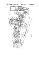
- FIG. 1 is a perspective view showing a forklift vehicle in position to be moved into mounting engagement with a carrier vehicle and showing attachment means according to the invention
- FIG. 2 is a side sectional view of a suspension link shown in FIG. 1;
- FIG. 3 is a side view of the forklift vehicle of FIG. 1 being advanced into raising position
- FIG. 4 is a side view similar to that of FIG. 3 showing the forklift vehicle in raised position
- FIG. 5 is a side view similar to that of FIG. 3 showing the forklift vehicle in raised and fully advanced position;
- FIG. 6 is a view similar to that of FIG. 5 but showing the forks of the forklift vehicle moved out of load carrying position;
- FIGS. 7, 8, 9 and 10 each show modified wheel pockets according to the invention.
- FIG. 1 shows a forklift vehicle 10 of the kind shown in our co-pending patent application Ser. No. 330,327.
- the forklift vehicle 10 has a frame 12 formed by a pair of elongated, parallel, laterally spaced longitudinal frame members 14, 16 and a transverse rear frame member 18 which connects the rear ends of the frame members 14, 16.
- Each frame member 14, 16 has near its front an integral, triangular downwardly extending plate 20.
- Axles 22 are mounted on and project outwardly from the bottoms of plates 20 and carry front wheels 24.
- the front wheels 24 are pneumatic inflatable tires of substantial diameter, to facilitate travel over rough terrain along a forward and rearward path of travel as indicated by arrow A.
- the rear of the vehicle 10 is supported by a pair of rear wheels 26 which are centered under the rear transverse frame member 18.
- the rear wheels 26 serve to drive and steer the vehicle.
- the fork carriage 28 which carries a fork tower 30.
- the fork carriage 28 includes a pair of carriage side members 32 which are movable forwardly and rearwardly along rails 34 located atop the frame members.
- the carriage side members 32 are supported by rollers 36 and are driven by a hydraulic motor 38 which drives a pinion (not shown) which engages rack teeth 40 located on the underside of rails 34.
- a transverse tube 44 extends between and is welded to the carriage side members 32.
- the base 46 of fork tower 30 is slidably and pivotally mounted on the tube 44 by rollers not shown.
- the fork tower 30 includes a pair of tower channels 48 fixed to the base 46 and connected at their tops by a U-shaped tube 50, a conventional vertically movable mast 52 formed by side channels 54 connected together by a top cross member 56 and a bottom cross member not shown, and a pair of forks 58.
- the forks which have forwardly projecting tines 59, are secured to chains 60.
- the chains 60 pass over upper sprockets 62 and lower sprockets not shown on the mast, and the chains are secured to brackets 64 welded to the tower channels 48.
- the mast 52 is raised and lowered by a piston 66 and piston rod 68, and as is conventional, as the mast is raised and lowered, the forks 58 will rise and fall at twice the rate of the mast.
- the entire fork tower 30 can be tilted forwardly and rearwardly by pistons 70 connected between the carriage side members 32 and the tower channels 48.
- the fork tower can be side shifted by a cylinder 72 connected between one of the carriage side members 32 and the tower base 46.
- the entire fork carriage 28 including the forks 58 can be moved forwardly and rearwardly along the frame of the forklift vehicle, and in addition the side to side position and tilt of the fork tower 30 and hence of the forks 58 can be adjusted.
- the carrier vehicle is shown as a truck 74 (it could equally be the trailer of a tractor trailer).
- the truck 74 includes an upper deck 76, and a pair of wheel pockets 78 located beneath the upper deck and behind the rear wheels 80 of the truck.
- the wheel pockets 78 will normally be secured to the frame, not shown, of the truck since they carry considerable load.
- Each wheel pocket 78 includes a front wheel engaging surface 82, a lower wheel supporting surface 84, and an upper wheel engaging surface 86.
- the vertical distance between the upper and lower surfaces 84, 86 of each wheel pocket 78 is made equal to the normal diameter of the front wheel 24 of the forklift vehicle plus a small clearance, so that the wheel 24 will normally be received relatively snugly within the wheel pocket.
- Side flanges 88 on the wheel pocket prevent sideways movement of the wheels 24 out of the wheel pockets and strengthen the wheel pockets.
- the side flanges 88 are spaced sufficiently far apart to allow a reasonable clearance for the front wheels 24 to enter the wheel pockets.
- the carrier vehicle 74 further includes, beneath its upper deck 76, front and rear cross bars 90, 92.
- Rear cross bar 92 is spaced below the rear of the upper deck 76 and its upper surface is located at a height convenient for the fork tines 59 to pass immediately thereabove as the forklift vehicle is being loaded onto the carrier vehicle.
- the front cross bar 90 is located between the rear bar 92 and the wheel pockets 78, and its bottom surface is spaced above the top surface of the rear bar 92 by a distance slightly greater than the thickness of the fork tines 59 in a vertical direction.
- the bars 90, 92 are supported from the truck frame by vertical struts 94, 96 at their edges and are braced by diagonal struts 98 extending between the vertical struts.
- the diagonal struts 98 allow the rear bar 92 to perform double duty as a bumper for the carrier vehicle.
- brackets 100 Secured at the rear vertical edge of the deck of the carrier vehicle are a pair of brackets 100, each containing an outwardly facing pin 102.
- the pins 102 are adapted to receive an eye socket 104 in one end of a suspension link 106.
- the other end of the suspension link 106 contains a further eye socket 108 adapted to fit over an outwardly facing pin 110 which is secured to the lower rear corner of each frame member 14, 16 of the forklift vehicle.
- each suspension link 106 is formed from a tube 112 and a shaft 114 telescopically fitted together.
- Shaft 114 has a collar 116 welded to its outer surface at its inner end, and tube 112 has a similar collar 118 welded to its inner surface at its free end (after shaft 114 has been fitted therein).
- the two collars 116, 118 abut when the link 106 is extended and prevent separation or further extension of the tube 112 and shaft 114.
- FIGS. 3 to 6 inclusive The manner in which the forklift vehicle is mounted on the carrier vehicle is best shown in FIGS. 3 to 6 inclusive.
- the forklift vehicle is first positioned so that its front wheels 24 are generally laterally aligned with wheel pockets 78.
- the height of the fork tines 59 is then adjusted so that they can pass over the rear cross bar 92 but beneath the front cross bar 90.
- the forklift vehicle is then driven forwardly as shown in FIG. 3, until the fork tines 59 are positioned with their front tips located below the front cross bar 90.
- the forklift vehicle is then raised, by lowering the forks, to the position shown in FIG. 4, in which the front wheels 24 are generally vertically aligned with the wheel pockets 78. At this time the weight of the forklift vehicle is supported by cross bars 90, 92.
- the fork carriage 28 is activated to retract the fork carriage, moving the frame 12 of the forklift vehicle forwardly and carrying the front wheels 24 into the wheel pockets 78, as shown in FIG. 5. It will be noted that if the side to side alignment of the forklift vehicle is not accurate, the forklift vehicle can be side shifted relative to the wheel pockets 78 at any time during the mounting process, by activating the side shift cylinder 72.
- the driver of the forklift vehicle simultaneously tilts the tower 30 rearwardly (by operating tower tilt cylinders 70) and drives the forks downwardly (by operating the piston 66). This raises the rear of the forklift vehicle frame 12, shortening the linear distance between pins 102 on the carrier vehicle and pins 110 on the forklift vehicle. (If the tower 30 were tilted rearwardly without at the same time driving the forks downwardly, the wheels 24 would tend simply to be pressed onto the bottoms of the wheel pockets 78 without raising the rear of the forklift vehicle.)
- the driver now telescopes (i.e. shortens) the suspension links 106 slightly and fits them over the pins 102, 110 on the carrier and forklift vehicles.
- Conventional retaining pins (not shown) are then inserted through holes (not shown) in the free ends of pins 102, 110 to retain the suspension links 106 in position.
- the tower 30 is tilted forwardly and the forks 58 are raised until, as shown in FIG. 6, all weight has been removed from the fork tines 59 and the cross bars 90, 92.
- the forklift vehicle is now supported solely by the engagement of the front wheels 24 in the wheel pockets 78, and by the suspension links 106.
- links 106 could be placed in links 106 to cushion their telescoping action.
- the links 106 could be made from very sturdy cable if desired. However, the lengths of the links 106 must be quite accurate (typically to within about one quarter inch) and will vary from one carrier vehicle to another. It is very difficult to cut cable and place a termination on it where the length of the cable must be accurately controlled, particularly when the customer is installing the equipment and lacks specialized equipment. In addition, cables can stretch. With the links 106, the customer is given tube 112, and is also given shaft 114 with collar 116 welded thereto and collar 118 loose thereon.
- the arrangement described is extremely simple, in that it requires little mechanical structure on the carrier vehicle; the structure used is extremely sturdy, and the operations required to load and unload the forklift vehicle are simple and can be performed quickly.
- the only springs employed are the resilient front tires of the forklift vehicle itself, which act as air cushions or springs; there are no other springs to stretch or become damaged.
- the links 106 need not be telescopic but can simply be made each as a single rigid bar.
- the telescopic feature facilitates mounting the forklift vehicle on the carrier vehicle.
- the clearance between the upper wheel engaging surface 86 of each wheel pocket and the top of the front wheel therein can be relatively substantial, e.g. about 5 inches, if desired. Tests show that the tendancy of the front wheels to move upwardly during transport of the forklift vehicle is somewhat limited. However, a smaller clearance, e.g. about 2 inches, is preferred.
- FIG. 7 shows a wheel pocket 78' having a flat bottom plate 84' and a forwardly and downwardly sloping flat upper plate 86' which combines the functions of the front plate 82 and upper plate 86.
- the side flanges 88 are still present.
- One advantage of the wheel pocket 78' is that it will accommodate front wheels of different sizes (but the links 106 will be dimensioned to ensure that the front wheels are located at the fronts of the wheel pockets).
- the upper plate can be curved, as shown at 86" for wheel pocket 78" in FIG. 8. This reduces the height needed for the wheel pocket, and provides a better stop against the upper surface of the front wheel.
- the front plate 82"' can slope forwardly and downwardly from the top plate 86"'.
- a single front crossbar 82"" can be used, as shown in FIG. 10, extending between the flanges 88 to block forward movement of the front wheel.
- crossbars 90, 92 which are used to support the forks while the forklift vehicle is being raised into position, can if desired be replaced by a pair of sleeves or pockets (not shown) into which the forks will extend. There should be sufficient clearance for the forks in such sleeves or pockets that the weight of the forklift vehicle can be removed from the forks, as shown in FIG. 6, so that bouncing of the forklift vehicle is still absorbed by the front wheels.
Landscapes
- Engineering & Computer Science (AREA)
- Transportation (AREA)
- Mechanical Engineering (AREA)
- Structural Engineering (AREA)
- Health & Medical Sciences (AREA)
- Public Health (AREA)
- Civil Engineering (AREA)
- Life Sciences & Earth Sciences (AREA)
- Geology (AREA)
- Forklifts And Lifting Vehicles (AREA)
Abstract
Description
Claims (13)
Priority Applications (2)
| Application Number | Priority Date | Filing Date | Title |
|---|---|---|---|
| CA000381684A CA1164503A (en) | 1981-07-14 | 1981-07-14 | Apparatus for mounting a forklift vehicle on a carrier vehicle |
| US06/296,770 US4396341A (en) | 1981-07-14 | 1981-08-27 | Apparatus for mounting a forklift vehicle on a carrier vehicle |
Applications Claiming Priority (2)
| Application Number | Priority Date | Filing Date | Title |
|---|---|---|---|
| CA000381684A CA1164503A (en) | 1981-07-14 | 1981-07-14 | Apparatus for mounting a forklift vehicle on a carrier vehicle |
| US06/296,770 US4396341A (en) | 1981-07-14 | 1981-08-27 | Apparatus for mounting a forklift vehicle on a carrier vehicle |
Publications (1)
| Publication Number | Publication Date |
|---|---|
| US4396341A true US4396341A (en) | 1983-08-02 |
Family
ID=25669370
Family Applications (1)
| Application Number | Title | Priority Date | Filing Date |
|---|---|---|---|
| US06/296,770 Expired - Lifetime US4396341A (en) | 1981-07-14 | 1981-08-27 | Apparatus for mounting a forklift vehicle on a carrier vehicle |
Country Status (2)
| Country | Link |
|---|---|
| US (1) | US4396341A (en) |
| CA (1) | CA1164503A (en) |
Cited By (26)
| Publication number | Priority date | Publication date | Assignee | Title |
|---|---|---|---|---|
| US4571139A (en) * | 1981-08-24 | 1986-02-18 | Superior Handling Equipment, Inc. | Self-propelled freight handling truck |
| US4613272A (en) * | 1984-02-02 | 1986-09-23 | Bielefelder Kuchenmaschinen-Und Transportgeratefabrik Gmbh | Method of operation for loading a motorized floor truck and support carriage therefor |
| EP0204363A1 (en) * | 1985-05-24 | 1986-12-10 | Selectiebedrijf Kooi Beheer B.V. | An apparatus for the transportation of a fork-lift truck on a lorry |
| FR2669588A1 (en) * | 1990-11-28 | 1992-05-29 | Audureau Omfort | On-board forklift truck support device |
| US5370494A (en) * | 1993-07-13 | 1994-12-06 | Holmes; Arthur J. | Self-propelled lift truck |
| EP0643009A1 (en) * | 1993-09-10 | 1995-03-15 | Fdi- Sambron S.A. | System for attaching a fork lifter with at least four attaching elements, attaching support and corresponding fork lifter |
| US5480275A (en) * | 1993-10-18 | 1996-01-02 | Taylor Iron-Machine Works, Inc. | Fork lift truck |
| WO1996033944A1 (en) * | 1995-04-26 | 1996-10-31 | Teledyne Industries Inc. | Mounting a forklift on a carrier |
| US5651658A (en) * | 1993-07-13 | 1997-07-29 | Holmes; Arthur Jack | Articulated lift truck |
| GB2313588A (en) * | 1996-05-31 | 1997-12-03 | Moffett Res & Dev Ltd | A Forklift Truck Mounting Frame |
| US5876175A (en) * | 1996-04-03 | 1999-03-02 | Manitou Bf | Device for securement of a goods handling carriage to a truck corresponding support chassis and truck |
| US5879124A (en) * | 1997-04-14 | 1999-03-09 | Gerardus J. Brouwer | Vehicle with retractible rear wheel assembly |
| US6059330A (en) * | 1996-05-31 | 2000-05-09 | Moffett Research And Development Limited | Vehicle crash bar assembly |
| US6062800A (en) * | 1998-02-24 | 2000-05-16 | Eagle Picher Industries, Inc. | Forklift frame and mounting kit |
| US6530739B1 (en) * | 2000-09-12 | 2003-03-11 | Boris Fridman | Vehicle mounted forklift mounting system and a forklift and carrier using the same |
| US6572322B2 (en) | 2000-11-15 | 2003-06-03 | Cargotec, Inc. | Mounting system for truck mounted beverage handler |
| EP0701963B2 (en) † | 1994-09-14 | 2004-08-18 | Manitou Bf | Motorised lift truck with telescopic arm |
| US20060245892A1 (en) * | 2005-03-11 | 2006-11-02 | Thomas Milani | Apparatus and method for the disposal of waste |
| US20080044265A1 (en) * | 2006-08-17 | 2008-02-21 | Steven Borntrager | Powered hand truck |
| US20080292448A1 (en) * | 2007-05-23 | 2008-11-27 | Moffett Research & Development Limited | Method for mounting a forklift to a vehicle |
| US20080292437A1 (en) * | 2007-05-23 | 2008-11-27 | Moffett Research & Development Limited | Mounting system for mounting a forklift on a vehicle |
| WO2008147218A3 (en) * | 2007-05-30 | 2009-01-22 | Olav Lauvdal | Forklift truck and method for transporting a forklift truck |
| US20100183412A1 (en) * | 2006-08-17 | 2010-07-22 | Steven Borntrager | Powered hand truck |
| US20110052354A1 (en) * | 2008-01-22 | 2011-03-03 | Mcgrane Barry | Top mount method and system |
| US20110058921A1 (en) * | 2008-01-22 | 2011-03-10 | Mcgrane Barry | Mounting kit |
| US20190351927A1 (en) * | 2018-05-21 | 2019-11-21 | The Raymond Corporation | Systems and methods for a universal mount and universal frame on a material handling vehicle |
Citations (3)
| Publication number | Priority date | Publication date | Assignee | Title |
|---|---|---|---|---|
| US3785517A (en) * | 1971-09-30 | 1974-01-15 | W Brajkovich | Motorcycle carrier and chock |
| US3799379A (en) * | 1973-01-26 | 1974-03-26 | T Grether | Fork lift |
| US3963129A (en) * | 1975-01-20 | 1976-06-15 | Clayton Jack E | Motorcycle carrier |
-
1981
- 1981-07-14 CA CA000381684A patent/CA1164503A/en not_active Expired
- 1981-08-27 US US06/296,770 patent/US4396341A/en not_active Expired - Lifetime
Patent Citations (3)
| Publication number | Priority date | Publication date | Assignee | Title |
|---|---|---|---|---|
| US3785517A (en) * | 1971-09-30 | 1974-01-15 | W Brajkovich | Motorcycle carrier and chock |
| US3799379A (en) * | 1973-01-26 | 1974-03-26 | T Grether | Fork lift |
| US3963129A (en) * | 1975-01-20 | 1976-06-15 | Clayton Jack E | Motorcycle carrier |
Cited By (42)
| Publication number | Priority date | Publication date | Assignee | Title |
|---|---|---|---|---|
| US4571139A (en) * | 1981-08-24 | 1986-02-18 | Superior Handling Equipment, Inc. | Self-propelled freight handling truck |
| US4613272A (en) * | 1984-02-02 | 1986-09-23 | Bielefelder Kuchenmaschinen-Und Transportgeratefabrik Gmbh | Method of operation for loading a motorized floor truck and support carriage therefor |
| EP0204363A1 (en) * | 1985-05-24 | 1986-12-10 | Selectiebedrijf Kooi Beheer B.V. | An apparatus for the transportation of a fork-lift truck on a lorry |
| FR2669588A1 (en) * | 1990-11-28 | 1992-05-29 | Audureau Omfort | On-board forklift truck support device |
| US5651658A (en) * | 1993-07-13 | 1997-07-29 | Holmes; Arthur Jack | Articulated lift truck |
| US5370494A (en) * | 1993-07-13 | 1994-12-06 | Holmes; Arthur J. | Self-propelled lift truck |
| EP0643009A1 (en) * | 1993-09-10 | 1995-03-15 | Fdi- Sambron S.A. | System for attaching a fork lifter with at least four attaching elements, attaching support and corresponding fork lifter |
| FR2709711A1 (en) * | 1993-09-10 | 1995-03-17 | Audureau Omfort | System for attaching a forklift to at least four attachment elements, cradle for attachment and corresponding forklift. |
| US5480275A (en) * | 1993-10-18 | 1996-01-02 | Taylor Iron-Machine Works, Inc. | Fork lift truck |
| EP0701963B2 (en) † | 1994-09-14 | 2004-08-18 | Manitou Bf | Motorised lift truck with telescopic arm |
| US6120232A (en) * | 1995-04-26 | 2000-09-19 | Terex Corporation | Apparatus and method for mounting a forklift on a carrier |
| US6024535A (en) * | 1995-04-26 | 2000-02-15 | Teledyne Princeton, Inc. | Method for mounting a forklift on a carrier |
| WO1996033944A1 (en) * | 1995-04-26 | 1996-10-31 | Teledyne Industries Inc. | Mounting a forklift on a carrier |
| US5813820A (en) * | 1995-04-26 | 1998-09-29 | Teledyne Princeton, Inc. | Apparatus and method for mounting a forklift on a carrier |
| US5575604A (en) * | 1995-04-26 | 1996-11-19 | Teledyne Princeton, Inc. | Apparatus and method for mounting a forklift on a carrier |
| US5876175A (en) * | 1996-04-03 | 1999-03-02 | Manitou Bf | Device for securement of a goods handling carriage to a truck corresponding support chassis and truck |
| GB2313588B (en) * | 1996-05-31 | 2000-03-01 | Moffett Res & Dev Ltd | A forklift truck mounting frame |
| US6059330A (en) * | 1996-05-31 | 2000-05-09 | Moffett Research And Development Limited | Vehicle crash bar assembly |
| GB2313588A (en) * | 1996-05-31 | 1997-12-03 | Moffett Res & Dev Ltd | A Forklift Truck Mounting Frame |
| US5749695A (en) * | 1996-05-31 | 1998-05-12 | Moffett Research And Development Limited | Forklift truck mounting frame |
| US5879124A (en) * | 1997-04-14 | 1999-03-09 | Gerardus J. Brouwer | Vehicle with retractible rear wheel assembly |
| US6062800A (en) * | 1998-02-24 | 2000-05-16 | Eagle Picher Industries, Inc. | Forklift frame and mounting kit |
| US6530739B1 (en) * | 2000-09-12 | 2003-03-11 | Boris Fridman | Vehicle mounted forklift mounting system and a forklift and carrier using the same |
| US6572322B2 (en) | 2000-11-15 | 2003-06-03 | Cargotec, Inc. | Mounting system for truck mounted beverage handler |
| US7789612B2 (en) | 2005-03-11 | 2010-09-07 | Thomas Milani | Apparatus and method for the disposal of waste |
| US20060245892A1 (en) * | 2005-03-11 | 2006-11-02 | Thomas Milani | Apparatus and method for the disposal of waste |
| US20100316482A1 (en) * | 2005-03-11 | 2010-12-16 | Thomas Milani | Method for the disposal of waste |
| US7597522B2 (en) * | 2006-08-17 | 2009-10-06 | Steven Borntrager | Powered hand truck |
| US8186931B2 (en) | 2006-08-17 | 2012-05-29 | Steven Borntrager | Powered hand truck |
| US20080044265A1 (en) * | 2006-08-17 | 2008-02-21 | Steven Borntrager | Powered hand truck |
| US7704035B2 (en) | 2006-08-17 | 2010-04-27 | Steven Borntrager | Powered hand truck |
| US20100183412A1 (en) * | 2006-08-17 | 2010-07-22 | Steven Borntrager | Powered hand truck |
| US7927063B2 (en) | 2007-05-23 | 2011-04-19 | Moffett Research & Development Limited | Method for mounting a forklift to a vehicle |
| US20080292448A1 (en) * | 2007-05-23 | 2008-11-27 | Moffett Research & Development Limited | Method for mounting a forklift to a vehicle |
| US7927061B2 (en) | 2007-05-23 | 2011-04-19 | Moffett Research & Development Limited | Mounting system for mounting a forklift on a vehicle |
| US20080292437A1 (en) * | 2007-05-23 | 2008-11-27 | Moffett Research & Development Limited | Mounting system for mounting a forklift on a vehicle |
| WO2008147218A3 (en) * | 2007-05-30 | 2009-01-22 | Olav Lauvdal | Forklift truck and method for transporting a forklift truck |
| US20110052354A1 (en) * | 2008-01-22 | 2011-03-03 | Mcgrane Barry | Top mount method and system |
| US20110058921A1 (en) * | 2008-01-22 | 2011-03-10 | Mcgrane Barry | Mounting kit |
| US8858153B2 (en) * | 2008-01-22 | 2014-10-14 | Barry McGrane | Top mount method and system |
| US20190351927A1 (en) * | 2018-05-21 | 2019-11-21 | The Raymond Corporation | Systems and methods for a universal mount and universal frame on a material handling vehicle |
| US11180172B2 (en) * | 2018-05-21 | 2021-11-23 | The Raymond Corporation | Systems and methods for a universal mount and universal frame on a material handling vehicle |
Also Published As
| Publication number | Publication date |
|---|---|
| CA1164503A (en) | 1984-03-27 |
Similar Documents
| Publication | Publication Date | Title |
|---|---|---|
| US4396341A (en) | Apparatus for mounting a forklift vehicle on a carrier vehicle | |
| US3799379A (en) | Fork lift | |
| KR100718660B1 (en) | Device for loading and unloading a storage container with respect to a transport vehicle and associated system and method | |
| US3861716A (en) | Platform lift transporter | |
| EP1827900B1 (en) | Tow trailer assembly | |
| US4606692A (en) | Quick-mount loader for articulated tractors | |
| US3863782A (en) | Self-loading article transport vehicle | |
| US5332345A (en) | Vehicle carrier | |
| US4859133A (en) | Fork lift truck and vehicle for the transport thereof | |
| US6428047B1 (en) | Combine header transport trailer | |
| US6062800A (en) | Forklift frame and mounting kit | |
| US2868401A (en) | Vehicle body changing method | |
| US20170120794A1 (en) | Dual Axis Tow Lift | |
| US6830422B2 (en) | Container transport apparatus | |
| US6530739B1 (en) | Vehicle mounted forklift mounting system and a forklift and carrier using the same | |
| US4437807A (en) | Wheeled trailer frame carrying unit attachment for lift truck | |
| US20070095616A1 (en) | Forklift trucks | |
| US7001131B2 (en) | Forklift loading support | |
| CA2707527C (en) | A mounting kit | |
| US4273500A (en) | Low profile lift attachment for a forklift | |
| US4714273A (en) | Vehicle for transporting elongated objects | |
| US3894747A (en) | Method and apparatus for lowering a trailer to the ground | |
| US4044999A (en) | Camper jack | |
| US3912097A (en) | Vehicle transport loading and servicing means | |
| EP1457456B1 (en) | Forklift truck |
Legal Events
| Date | Code | Title | Description |
|---|---|---|---|
| AS | Assignment |
Owner name: BROUWER TURF EQUIPMENT LIMITED, WOODBINE AVE., KES Free format text: ASSIGNMENT OF ASSIGNORS INTEREST.;ASSIGNORS:BROUWER, GERARDUS J.;ARNOLD, WILLIAM T.;REEL/FRAME:003916/0785 Effective date: 19810819 |
|
| STCF | Information on status: patent grant |
Free format text: PATENTED CASE |
|
| MAFP | Maintenance fee payment |
Free format text: PAYMENT OF MAINTENANCE FEE, 4TH YEAR, PL 96-517 (ORIGINAL EVENT CODE: M170); ENTITY STATUS OF PATENT OWNER: LARGE ENTITY Year of fee payment: 4 |
|
| AS | Assignment |
Owner name: CUSHMAN INC., A CORP. OF DE, NEBRASKA Free format text: ASSIGNMENT OF ASSIGNORS INTEREST.;ASSIGNOR:OUTBOARD MARINE CORPORATION;REEL/FRAME:005159/0016 Effective date: 19890619 |
|
| MAFP | Maintenance fee payment |
Free format text: PAYMENT OF MAINTENANCE FEE, 8TH YEAR, PL 96-517 (ORIGINAL EVENT CODE: M171); ENTITY STATUS OF PATENT OWNER: LARGE ENTITY Year of fee payment: 8 |
|
| FEPP | Fee payment procedure |
Free format text: PAYOR NUMBER ASSIGNED (ORIGINAL EVENT CODE: ASPN); ENTITY STATUS OF PATENT OWNER: LARGE ENTITY |
|
| MAFP | Maintenance fee payment |
Free format text: PAYMENT OF MAINTENANCE FEE, 12TH YEAR, LARGE ENTITY (ORIGINAL EVENT CODE: M185); ENTITY STATUS OF PATENT OWNER: LARGE ENTITY Year of fee payment: 12 |
|
| FEPP | Fee payment procedure |
Free format text: PAT HLDR NO LONGER CLAIMS SMALL ENT STAT AS SMALL BUSINESS (ORIGINAL EVENT CODE: LSM2); ENTITY STATUS OF PATENT OWNER: LARGE ENTITY |
|
| AS | Assignment |
Owner name: STEINER TURF EQUIPMENT INC., OHIO Free format text: ASSIGNMENT OF ASSIGNORS INTEREST;ASSIGNOR:BROUWER TURF EQUIPMENT LIMITED;REEL/FRAME:008022/0672 Effective date: 19960626 |