US4389682A - Magnetic recording systems - Google Patents
Magnetic recording systems Download PDFInfo
- Publication number
- US4389682A US4389682A US06/180,614 US18061480A US4389682A US 4389682 A US4389682 A US 4389682A US 18061480 A US18061480 A US 18061480A US 4389682 A US4389682 A US 4389682A
- Authority
- US
- United States
- Prior art keywords
- read
- waveform
- transformed
- transitions
- medium
- Prior art date
- Legal status (The legal status is an assumption and is not a legal conclusion. Google has not performed a legal analysis and makes no representation as to the accuracy of the status listed.)
- Expired - Lifetime
Links
- 230000007704 transition Effects 0.000 claims abstract description 32
- 238000010897 surface acoustic wave method Methods 0.000 claims abstract description 23
- 238000005070 sampling Methods 0.000 claims abstract description 17
- 238000000034 method Methods 0.000 claims description 23
- 230000001131 transforming effect Effects 0.000 claims description 9
- 238000000605 extraction Methods 0.000 claims description 5
- 230000004044 response Effects 0.000 claims description 5
- 230000001419 dependent effect Effects 0.000 claims description 4
- 230000009466 transformation Effects 0.000 claims description 4
- 238000011084 recovery Methods 0.000 abstract description 3
- 230000008569 process Effects 0.000 description 14
- 230000000694 effects Effects 0.000 description 3
- 210000001520 comb Anatomy 0.000 description 2
- 230000003111 delayed effect Effects 0.000 description 2
- 238000001514 detection method Methods 0.000 description 2
- 238000010586 diagram Methods 0.000 description 2
- 230000004907 flux Effects 0.000 description 2
- 230000008859 change Effects 0.000 description 1
- 230000001427 coherent effect Effects 0.000 description 1
- 238000010276 construction Methods 0.000 description 1
- 239000013078 crystal Substances 0.000 description 1
- 230000001934 delay Effects 0.000 description 1
- 230000008030 elimination Effects 0.000 description 1
- 238000003379 elimination reaction Methods 0.000 description 1
- 230000002349 favourable effect Effects 0.000 description 1
- 230000001360 synchronised effect Effects 0.000 description 1
- 238000004804 winding Methods 0.000 description 1
Images


Classifications
-
- G—PHYSICS
- G11—INFORMATION STORAGE
- G11B—INFORMATION STORAGE BASED ON RELATIVE MOVEMENT BETWEEN RECORD CARRIER AND TRANSDUCER
- G11B5/00—Recording by magnetisation or demagnetisation of a record carrier; Reproducing by magnetic means; Record carriers therefor
- G11B5/02—Recording, reproducing, or erasing methods; Read, write or erase circuits therefor
- G11B5/09—Digital recording
-
- G—PHYSICS
- G11—INFORMATION STORAGE
- G11B—INFORMATION STORAGE BASED ON RELATIVE MOVEMENT BETWEEN RECORD CARRIER AND TRANSDUCER
- G11B20/00—Signal processing not specific to the method of recording or reproducing; Circuits therefor
- G11B20/10—Digital recording or reproducing
- G11B20/10009—Improvement or modification of read or write signals
- G11B20/10046—Improvement or modification of read or write signals filtering or equalising, e.g. setting the tap weights of an FIR filter
Definitions
- This invention relates to digital magnetic recording systems, especially for high density recording, such as is used for example with magnetic-disc devices.
- the magnetic recording process can be divided into two parts, which in a digital context are usually called the write process and the read process.
- the write process In high-density digital recording the write process normally records the digital information as a sequence of transitions between regions of a magnetic medium that are approximately fully magnetised in opposite senses. This process exploits the non-linear recording properties of the medium and allows transitions to be written very close together. There are no corresponding non linearities in the read process, so the read pulses resulting from neighbouring transitions will, as the transitions are brought closer together, overlap and superpose. This process, which will be referred to herein as "interference,” makes it difficult to distinguish the individual pulses and recover the recorded information. It is therefore possible to write transitions closer together than they can be resolved by the read process.
- the read process is therefore the factor which limits the density with which information can be recorded. If it could be improved the storage capacity of the medium and the rate at which data can be read out could be increased.
- This invention provide a digital magnetic recording system the read channel of which includes a read head and a surface acoustic wave transversal filter the characteristics of which are such as to transform, or assist in transforming, the read waveform into a waveform from which the recovery of the recorded information is facilitated.
- the invention provides apparatus for reproducing digital information recorded on a magnetic medium as transitions between regions of the medium magnetised in opposite senses, the apparatus comprising:
- a read head for outputting a read waveform on relative movement between the magnetic medium and the read head, the read waveform being composed of read pulses each resulting from the relative movement of a single one of the said transitions past the read head, and read pulses being subject to interference with one another;
- means for transforming the read waveform into a transformed waveform which means comprise in sequence a modulator arranged to modulate a carrier wave in accordance with an input derived from the output of the read head, a surface acoustic wave transversal filter and a demodulator arranged to remove the said carrier wave; and
- the means for extracting from the transformed waveform a digital signal dependent on the recorded information the characteristics of the surface acoustic wave transversal filter being chosen, in conjunction with those of the remainder of the transforming means, in such a way as to facilitate the extraction of the said digital signal by controlling the manner in which, or at least reducing the extent to which, the transformed versions of the read pulses interfere with one another in the transformed waveform.
- the invention further provides a method of reading digital information recorded on a magnetic medium as transitions between regions of the medium magnetised in opposite senses, the method comprising:
- the read head being thereby caused to output a read waveform composed of read pulses each resulting from the relative movement of a single one of the said transitions past the read head, read pulses being subject to interference with one another;
- transforming the read waveform into a transformed waveform by means which comprise in sequence a modulator in which a carrier wave is modulated in accordance with an input derived from the output of the read head, a surface acoustic wave transversal filter and a demodulator in which the said carrier wave is removed;
- the characteristics of the surface acoustic wave transversal filter being chosen, in conjunction with those of the remainder of the transforming means, in such a way as to facilitate the extraction of the said digital signal by controlling the manner in which, or at least reducing the extent to which, the transformed versions of the read pulses interfere with one another in the transformed waveform.
- a surface acoustic wave transversal filter in accordance with the invention makes it possible to increase the density with which information can be recorded as compared with the case in which the information is recovered from the untransformed read waveform.
- FIG. 1 is a block diagram of the system
- FIG. 2a through h show waveforms arising at various points in the system
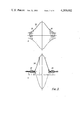
- FIG. 3 shows waveforms in more detail
- FIG. 4 illustrates how the transformed waveform of FIG. 3 is derived.
- the system writes and reads digital data on a magnetic medium 1.
- the medium may, for example, be a magnetic disc, although the technique to be described may equally well be used in other high-density digital recording applications.
- the information to be recorded is supplied as a write current to a write head 2 past which the medium in operation moves.
- the write current switches between a positive and a negative value (see also the waveform of FIG. 2a). While the current is steady at one of these values it magnetises the medium to saturation in one direction; after it has switched to the other value it magnetises the medium in the opposite direction; and between the two regions magnetised in opposite directions is a very thin transition region which coincides with the instant of switching.
- the instants at which switching is allowed to take place occur at equally spaced intervals.
- the transitions therefore, can occur only at possible positions which are equally spaced on the medium.
- FIG. 2a they have been interpreted as representing a string of bits each of which occurs at one of the possible positions and using a non-return to zero encoding in which a one is represented by a transition at a possible position and a zero by the absence of a transition at a possible position. This is the most compact representation assuming that the positions at which transitions can occur are spaced as closely as the system allows.
- the bit sequence recorded may itself be an encoding of the original data.
- the information recorded on the medium 1 is read by a read head 3.
- the read head is shown as separate from the write head 2, because that allows the two heads to be optimised independently, but a combined read-write head can be used if desired.
- the magnetic medium 1 moves past the read head 3, and flux changes sensed by the head induce a voltage in the windings of the head. Flux changes are only experienced in the neighbourhood of the transitions, and an individual transition gives rise to a bell-shaped read pulse such as one of the pulses of FIG. 2b. As the read process is effectively linear, the pulses from different transitions may be summed to give the complete read waveform, as shown in FIG. 2c.
- the read waveform is transformed into a waveform from which the recorded information may be recovered more easily.
- This transformation is carried out principally by a surface acoustic wave transversal filter 4.
- the filter 4 operates not on the read waveform itself, but on that waveform modulated by an amplitude modulator 5 onto a high-frequency carrier wave from a source 6.
- the signal output by the surface acoustic wave transversal filter 4 is then demodulated by a coherent demodulator 7 to remove the carrier.
- any required frequency response can be achieved to a desired accuracy free (at the expense of a delay) from the restriction to which conventional filters are subject that the phase and amplitude of the output cannot be tailored independently.
- the techniques for designing a surface acoustic wave transversal filter to have a desired response are described in greater detail in, for example, Part 3 of "Surface acoustic filters, design, construction, and use,” edited by John Matthews and published by John Wiley and Sons in 1977.
- the principal tool in tailoring the response is the adjustment of the spacing and degree of overlap of the teeth of the transducer combs.
- the surface acoustic wave transversal filter is designed to transform the measured shape of a single read pulse 32, modulated onto the carrier 31, as shown in FIG. 3a, into a pulse as shown in FIG. 3b.
- the envelope 34 of the transformed pulse is of the Nyquist 2 form. That is, perhaps, most helpfully explained by reference to the Nyquist 1 form, which is shown in FIG. 4a.
- the Nyquist 2 form is obtained by adding together two Nyquist 1 waveforms the peaks of which are spaced apart by T, as shown in FIG. 4b.
- the resultant, as shown in FIG. 4, has the value 1 at 0 and T and is 0 at -T and ⁇ nT, where n is an integer greater than 1.
- the envelope of the waveform output by the surface acoustic wave transversal filter as shown in FIG. 3b has the Nyquist 2 form. It is, of course, delayed by the filter, but for convenience its peak is shown aligned with that of the read pulse, with the result that the waveform has a predetermined value equivalent to 1 at ⁇ 1/2T, and is 0 at ⁇ (n+1/2)T, where n is an integer greater than 0.
- the period T is chosen to be the interval between the passage past the read head 2 of two successive positions at which transition can occur.
- FIG. 2d shows the transformed versions of three read pulses (advanced, once again, so that they are aligned with the read pulses from which they are derived). Because the read process is (at any rate to a first approximation) linear, the superposition theorum applies and the total waveform is, as shown in FIG. 2e, the sum of the individual transformed pulses each derived by considering the effect of the filter 7 on a single read pulse.
- the demodulated waveform as shown in FIG. 2e is rectified by a rectifier 8 into what may be regarded as the final transformed waveform, as shown in FIG. 2f. (In practice the demodulator may carry out the rectification.)
- the transformed waveform is subjected to a recovery process by which the original recorded digital signal is recovered. In this process the waveform as shown in FIG. 2f is strobed at intervals equal to those at which the positions at which transitions can occur pass the read head 3, but displaced from the peak of an isolated read pulse in the final transformed waveform by half a period. At these times this waveform has the value 0 or 1.
- the final transformed waveform is strobed by a signal from a clock 9 applied to a sampling circuit 10 receiving the output of the rectifier 8. That produces the digital signal shown in FIG. 2g, which is applied to a scale-of-2 circuit 11.
- the circuit 11 recovers the original recorded digital information shown in FIG. 2a by changing its output when it receives a 1 and leaving it unchanged when it receives a 0. The effect of this operation is to remove the contribution of the pulse whose peak immediately precedes the strobe time on the occasions when that pulse is present.
- the output of the circuit 11 is shown in FIG. 2b (where it is delayed by half a period to restore alignment on the diagram with the original recorded information). It reproduces that recorded information and is the output from the read channel.
- the read signal is amplified by an amplifier 12 before being supplied to the modulator 5 for the surface acoustic wave transversal filter.
- the gain of the amplifier 12 is controllable, and a control circuit 13 monitors the waveform from the rectifier 8 and detects isolated peaks, which are compared with a reference to give rise to a signal changing the gain of the amplifier 12 if necessary in order to keep the amplitude of a transformed read pulse equal to a reference value (treated as "1" in the previous discussion) at the sampling times.
- the clock 9 is a controllable oscillator. It is controlled by a circuit 14 which compares the output of the clock 9 with the recorded information in order to keep the two in synchronism.
- the circuit 14 monitors the peaks of the waveform to direct those which are symmetrical, that is, those which are not shifted by interference. Their timing is compared with the clock output (displaced by half a period to coincide with the expected peak) and a signal issued to change the frequency or phase of the clock if the peak occurs earlier or later than expected.
- the recorded signal may contain redundant information to ensure that the longest possible period between synchronising pulses does not exceed a desired value. That also allows error detection and the elimination of a d c component in the write current resulting from unequal totals of ones and zeros.
- the filter giving Nyquist 2 transformed read pulse may be a pulse of another shape, for example Nyquist 1.
- detection of the recorded digits consists simply in sampling the amplitude of the final transformed waveform at the time of the expected peaks.
- This form has a less favourable signal-to-noise ratio.
- bit string recorded is output from the scale-of-two circuit 11.
- the information to be recorded may be precoded by being input to a scale-of-two circuit from the output of which the write current is derived.
- the scale-of-two circuit 11 is not used and the output of the sampling circuit 10 is itself the desired information.
- the bit string of 2g when put through a scale-of-two circuit, gives the bit string of FIG. 2a, and if precoded in this way and then recorded is recovered directly from the sampling circuit 10.
- the transformation to be performed may, if desired, be carried out in stages by more than one surface-acoustic wave transversal filter.
- the carrier frequency may be ten times the data rate, which for a data rate of 5 to 10 million bits per second implies a frequency of 50 to 100 megahertz.
- the filter according to the invention improves the signal to noise ratio of the read process, and therefore its ability to resolve the recorded bits, allowing them to be recorded more closely. Even assuming that imperfections cause departures from the ideal system described above it may be expected that it will allow the storage capacity and data rate of a current magnetic disc storage device to be increased by a factor of 1.5 to 2.
- Transversal filters have been implemented by forms of shift register such as the bucket-brigade transversal filter. That however necessitates a strobing waveform synchronised with the information signals, and this poses a difficult synchronism problem since the input to such a filter is ill-suited to the provision of precise timing signals.
- the carrier frequency of the surface acoustic wave transversal filter can be regarded as a strobe of so high a frequency as to avoid the need for synchronisation.
Landscapes
- Digital Magnetic Recording (AREA)
- Signal Processing For Digital Recording And Reproducing (AREA)
- Dc Digital Transmission (AREA)
Applications Claiming Priority (2)
| Application Number | Priority Date | Filing Date | Title |
|---|---|---|---|
| GB7930355 | 1979-08-31 | ||
| GB7930355 | 1979-08-31 |
Publications (1)
| Publication Number | Publication Date |
|---|---|
| US4389682A true US4389682A (en) | 1983-06-21 |
Family
ID=10507550
Family Applications (1)
| Application Number | Title | Priority Date | Filing Date |
|---|---|---|---|
| US06/180,614 Expired - Lifetime US4389682A (en) | 1979-08-31 | 1980-08-25 | Magnetic recording systems |
Country Status (7)
| Country | Link |
|---|---|
| US (1) | US4389682A (enExample) |
| JP (1) | JPS5661015A (enExample) |
| DE (1) | DE3032542A1 (enExample) |
| FR (1) | FR2464531A1 (enExample) |
| NL (1) | NL8004862A (enExample) |
| SE (1) | SE8006038L (enExample) |
| ZA (1) | ZA805184B (enExample) |
Families Citing this family (2)
| Publication number | Priority date | Publication date | Assignee | Title |
|---|---|---|---|---|
| ZA81781B (en) * | 1980-02-13 | 1982-03-31 | Int Computers Ltd | Digital systems |
| US4535371A (en) * | 1983-05-16 | 1985-08-13 | International Business Machines Corporation | Recording channel with signal controlled integrated analog circuits |
Citations (3)
| Publication number | Priority date | Publication date | Assignee | Title |
|---|---|---|---|---|
| US3775759A (en) * | 1972-01-21 | 1973-11-27 | Ibm | Magnetic recording and readback systems with raised cosine equalization |
| US3899666A (en) * | 1973-10-24 | 1975-08-12 | Rca Corp | Integral correlation and transverse equalization method and apparatus |
| US4081756A (en) * | 1976-12-30 | 1978-03-28 | Sperry Rand Corporation | Dual channel signal detector circuit |
Family Cites Families (4)
| Publication number | Priority date | Publication date | Assignee | Title |
|---|---|---|---|---|
| US3215995A (en) * | 1962-04-25 | 1965-11-02 | Ibm | Passive electric networks for magnetic storage system |
| GB1353019A (en) * | 1970-04-21 | 1974-05-15 | Xerox Corp | Channel-shaping filter |
| DE2126745A1 (de) * | 1971-05-28 | 1972-12-07 | Siemens Ag | Anordnung zur Korrektur von Verzerrungen bei sogenannten "partial-response"-Datensignalen |
| US3737808A (en) * | 1971-12-29 | 1973-06-05 | Honeywell Inf Systems | Pulse shaping network |
-
1980
- 1980-08-22 ZA ZA00805184A patent/ZA805184B/xx unknown
- 1980-08-25 US US06/180,614 patent/US4389682A/en not_active Expired - Lifetime
- 1980-08-28 NL NL8004862A patent/NL8004862A/nl not_active Application Discontinuation
- 1980-08-29 FR FR8018817A patent/FR2464531A1/fr active Granted
- 1980-08-29 SE SE8006038A patent/SE8006038L/ not_active Application Discontinuation
- 1980-08-29 DE DE19803032542 patent/DE3032542A1/de not_active Ceased
- 1980-08-30 JP JP12056880A patent/JPS5661015A/ja active Pending
Patent Citations (3)
| Publication number | Priority date | Publication date | Assignee | Title |
|---|---|---|---|---|
| US3775759A (en) * | 1972-01-21 | 1973-11-27 | Ibm | Magnetic recording and readback systems with raised cosine equalization |
| US3899666A (en) * | 1973-10-24 | 1975-08-12 | Rca Corp | Integral correlation and transverse equalization method and apparatus |
| US4081756A (en) * | 1976-12-30 | 1978-03-28 | Sperry Rand Corporation | Dual channel signal detector circuit |
Also Published As
| Publication number | Publication date |
|---|---|
| ZA805184B (en) | 1981-08-26 |
| DE3032542A1 (de) | 1981-03-19 |
| FR2464531B1 (enExample) | 1984-05-25 |
| NL8004862A (nl) | 1981-03-03 |
| SE8006038L (sv) | 1981-03-01 |
| FR2464531A1 (fr) | 1981-03-06 |
| JPS5661015A (en) | 1981-05-26 |
Similar Documents
| Publication | Publication Date | Title |
|---|---|---|
| US4355408A (en) | System for extracting timing information from a digital waveform | |
| US7764458B1 (en) | Up-sampled filtering for servo demodulation | |
| CA1214264A (en) | Digital data detecting apparatus | |
| US4202017A (en) | Magnetic recording signal equalization apparatus | |
| DE69317181D1 (de) | Einrichtung zur Wiedergabe eines digitalen Signals von einem Aufzeichnungsträger mit einem variablen Entzerrer | |
| US4219890A (en) | Digital signal regulation system | |
| US5319502A (en) | System and method for employing buried servos within a magnetic recording medium | |
| US4607296A (en) | Clock recovery system in digital rotary scan magnetic playback devices | |
| US3775759A (en) | Magnetic recording and readback systems with raised cosine equalization | |
| US4389682A (en) | Magnetic recording systems | |
| EP0427928A2 (en) | Feed forward differential equalizer for narrowing the signal pulses of magnetic heads | |
| US4327383A (en) | Read circuit for a floppy disk drive | |
| US4195318A (en) | High density bias linearized magnetic recording system utilizing Nyquist bandwidth partial response transmission | |
| US6091558A (en) | Device for write compensation in magnetic media recording | |
| US4330799A (en) | Interleaved dipulse sequence generating apparatus for data transmission or recording channels | |
| US3573770A (en) | Signal synthesis phase modulation in a high bit density system | |
| CA1171522A (en) | Multitrack recording with minimal intermodulation | |
| US3952329A (en) | Pulse compression recording | |
| Chi | Characterization and spectral equalization for hight-density disk recording | |
| US4492990A (en) | Noise reduction system | |
| GB2061047A (en) | Pulse shaping | |
| US3441921A (en) | Self-synchronizing readout with low frequency compensation | |
| US6288859B1 (en) | Device for write compensation in magnetic-media recording | |
| US4323932A (en) | Readback pulse compensator | |
| US5019919A (en) | Apparatus for recording and reproducing divided signals of an angle modulated signal |
Legal Events
| Date | Code | Title | Description |
|---|---|---|---|
| STCF | Information on status: patent grant |
Free format text: PATENTED CASE |