US4384517A - Full tonnage stop for hydraulic presses - Google Patents
Full tonnage stop for hydraulic presses Download PDFInfo
- Publication number
- US4384517A US4384517A US06/267,903 US26790381A US4384517A US 4384517 A US4384517 A US 4384517A US 26790381 A US26790381 A US 26790381A US 4384517 A US4384517 A US 4384517A
- Authority
- US
- United States
- Prior art keywords
- flange
- cylinder
- hydraulic press
- press according
- stop
- Prior art date
- Legal status (The legal status is an assumption and is not a legal conclusion. Google has not performed a legal analysis and makes no representation as to the accuracy of the status listed.)
- Expired - Fee Related
Links
- 238000006073 displacement reaction Methods 0.000 claims description 8
- 238000013459 approach Methods 0.000 abstract description 2
- 239000012530 fluid Substances 0.000 description 11
- 238000010276 construction Methods 0.000 description 2
- 230000002093 peripheral effect Effects 0.000 description 2
- 230000000717 retained effect Effects 0.000 description 2
- 230000008878 coupling Effects 0.000 description 1
- 238000010168 coupling process Methods 0.000 description 1
- 238000005859 coupling reaction Methods 0.000 description 1
- 230000000694 effects Effects 0.000 description 1
- 238000005242 forging Methods 0.000 description 1
- 238000009432 framing Methods 0.000 description 1
- 230000007257 malfunction Effects 0.000 description 1
- 238000012986 modification Methods 0.000 description 1
- 230000004048 modification Effects 0.000 description 1
- 238000007789 sealing Methods 0.000 description 1
Images


Classifications
-
- B—PERFORMING OPERATIONS; TRANSPORTING
- B30—PRESSES
- B30B—PRESSES IN GENERAL
- B30B15/00—Details of, or accessories for, presses; Auxiliary measures in connection with pressing
- B30B15/04—Frames; Guides
- B30B15/041—Guides
-
- B—PERFORMING OPERATIONS; TRANSPORTING
- B30—PRESSES
- B30B—PRESSES IN GENERAL
- B30B15/00—Details of, or accessories for, presses; Auxiliary measures in connection with pressing
- B30B15/28—Arrangements for preventing distortion of, or damage to, presses or parts thereof
Definitions
- This invention relates to the art of hydraulic presses and, more particularly, to an improved arrangement for positively stopping travel of the displaceable component of the hydraulic drive unit in the direction of movement thereof toward the press bed.
- a hydraulic press with a hydraulic drive unit of the character comprising a ram fixed with respect to the press frame and a cylinder slidably displaceable relative to the ram and operatively connected with the press slide to impart reciprocation thereto relative to the press bed.
- the ram is fixed to the crown portion of the press frame, and the drive cylinder component has an open upper end receiving the ram and defines a hydraulic fluid receiving variable volume chamber with the ram.
- the press slide is attached to the closed lower end of the cylinder and is displaced thereby toward the press bed by introducing hydraulic fluid between the ram and cylinder.
- Return movement of the cylinder and slide is achieved by hydraulic return cylinder units on the crown and connected to the cylinder.
- the open upper end of the cylinder component has been provided with a crosshead mechanically fastened to the cylinder such as by bolts extending through the crosshead and axially into the cylinder wall.
- Piston rods of the return cylinders are attached to the crosshead, and radially outer portions of the crosshead carry guide components engageable with gibbing on the press frame to provide support and guidance for the cylinder during reciprocation thereof.
- valve as mentioned above is mechanically actuated by the crosshead component on the cylinder, whereby it is extremely difficult to maintain accuracy of adjustment between the valve actuator and crosshead to achieve valve operation at the same time during each succeeding stroke of the drive cylinder and thus the press slide. Accordingly, considerable down time is required to maintain a satisfactory degree of accuracy with respect to such valve actuation and, when such accuracy is lost, either slide undertravel or overtravel can result. Overtravel is undesirable for the reason of the potential damage referred to hereinabove, and undertravel can result in inaccuracies with respect to the work performed on a workpiece in the press.
- an arrangement for positively stopping and taking the full tonnage load of the hydraulic drive unit upon movement of the drive cylinder and thus the slide to the desired position relative to the press bed.
- the drive cylinder is provided with an integral radially outwardly extending flange about the periphery thereof
- the press frame is provided with a stop plate arrangement axially spaced from the die space area of the press and positioned in the path of movement of the flange so as to be engaged thereby when the drive cylinder and thus the slide reaches the desired position relative to the press bed.
- the flange and stop plate have sufficient structural integrity to take the full tonnage load for which the press and hydraulic drive unit are designed and, thus, positively stop the slide in the desired position eliminating the possibility of both undertravel and overtravel of the slide.
- a positive stop arrangement advantageously eliminates potential mechanical damage to component parts of the return cylinder units, the gibbing, and the guide components associated with the flange of the drive cylinder.
- the arrangement according to the present invention advantageously eliminates the need for hydraulic fluid flow control through a mechanically or otherwise actuated dump valve, and provides continuity with respect to accuracy in controlling the position of the drive cylinder and thus the slide relative to the press bed.
- a further object is the provision of a stop arrangement for the drive cylinder which minimizes wear and avoids structural damage to component parts of the hydraulic drive unit and guidance components associated therewith.
- Another object is the provision of a positive, full tonnage stop arrangement for the drive cylinder in which the component parts of the stop arrangement are located outside the die space area of the press.
- Yet another object is the provision of a stop arrangement of the foregoing character which positively prevents overtravel of the press slide toward the press bed.
- Still a further object is the provision of a stop arrangement of the foregoing character enabling improved efficiency with respect to press operation and improved accuracy with respect to work performed on workpieces in the press.
- Yet another object is the provision of a stop arrangement of the foregoing character which is more economical to construct, use and maintain than stop arrangements heretofore employed and which at the same time provides improved accuracy with respect to continuously stopping the press slide in a desired position relative to the press bed during the working stroke of the press.
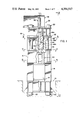
- FIG. 1 is a front elevation view, partially in section, of a hydraulic press incorporating the stop arrangement according to the present invention
- FIG. 2 is a side elevation view, partially in section, of the press as seen in the direction of line 2--2 in FIG. 1;
- FIG. 3 is a plan view, in section, taken along line 3--3 in FIG. 1 and showing the flange at the upper end of the drive cylinder;
- FIG. 4 is a detailed sectional elevation view taken along line 4--4 in FIG. 3 and showing the upper and lower gibbing arrangement for the drive cylinder and slide;
- FIG. 5 is a plan view, in section, taken along line 5--5 in FIG. 1 and showing the lower guidance arrangement for the drive cylinder and slide;
- FIG. 6 is a detailed sectional elevation view taken along line 6--6 in FIG. 3 and showing the return cylinder piston rod connection to the flange of the drive cylinder;
- FIG. 7 is a plan view, in section, taken along line 7--7 in FIG. 1 and showing the stop plate for the drive cylinder.
- FIGS. 1 and 2 of the drawing comprising a frame assembly including a lower portion 10 providing a bed area 12 at about floor level, corner post portion 14, an intermediate frame portion 16, and a crown portion 18.
- the latter frame portions are of welded construction and are interengaged in assembled relationship by means of tie rod units 20 at the four corners of the press.
- the hydraulic drive unit for the press is designated generally by the numeral 22 and includes a ram member 24 having a vertical axis 26, and a drive cylinder 28 received on and reciprocable relative to ram 24 as set forth more fully herinafter.
- Ram 24 has a radially outwardly extending peripheral flange 30 intermediate the opposite ends thereof and by which the ram is mounted such as by bolting to a frame plate 32 in crown portion 18, and the ram has a central passageway 34 communicating at its upper end with a source 36 of hydraulic fluid under pressure through a coupling 38 therebetween.
- the lower end of cylinder 28 is closed, thus to provide a variable volume hydraulic fluid receiving chamber with ram 24 and, in the embodiment illustrated, a slide member 40 is suitably attached to the closed lower end of cylinder 28 and thus is displaceable therewith relative to ram 24 during operation of the press.
- fluid flow to such return cylinder units is through suitable controls, not illustrated, which provide for piston rods 44 to descend freely with drive cylinder 28 until the slide reaches its lowermost position, at which time hydraulic fluid under pressure is introduced into cylinder units 42 to elevate cylinder 28 and thus slide 40.
- Such return movement of the slide is of course enabled by releasing hydraulic fluid under pressure between ram 24 and drive cylinder 28 for free flow through passageway 34 back to source 36.
- drive cylinder 28 includes a circular body portion 46 having radially inner and outer surfaces 46a and 46b, respectively, and a radially outwardly extending flange 48 integral with the body portion at the open upper end of the cylinder and extending about the periphery thereof.
- flange 48 is octagonal in plan view and has radially extending upper and lower sides 48a and 48b, respectively.
- the octagonal configuration of flange 48 provides the flange with diametrically opposed pairs of radially outer sides 50, 52, 54 and 56.
- each pair are planar and parallel to one another and extend axially between the upper and lower sides of flange 48.
- the open upper end of drive cylinder 28 is slidably and sealingly interengaged with ram 24 by means of an annular sealing ring assembly 58 received in an annular recess therefor on inner surface 46a of the cylinder and retained in place by means of an annular retaining ring 60 secured to cylinder 28 by means of a plurality of bolts 62.
- flange 48 of drive cylinder 28 is provided adjacent each of the pairs of sides 50 and 54 with an axially and radially extending recess 74 parallel to the corresponding radially outer side.
- Each recess 74 receives a pair of guide blocks 66 and corresponding shims 76, which guide blocks and shims are secured in recess 74 by means of a plurality of bolts 78.
- Each guide block 66 carries a corresponding wear plate 66a.
- Gibbing 64 for each guide block assembly is mounted on a corresponding gibbing support frame plate 80 in crown portion 18 of the press frame, and it will be appreciated of course that wear plates 66a on guide blocks 66 slidably engage the corresponding gibbing to provide lateral support and vertical guidance for drive cylinder 28 and slide member 40 during reciprocation thereof.
- the outer surface of slide member 40 is octagonal in cross-sectional configuration providing opposed pairs of parallel, axially extending planar surfaces 82, 84, 86 and 88 corresponding, respectively, to sides 50, 52, 54 and 56 of drive cylinder flange 48.
- guidance at the lower end is provided by guide blocks 70 mounted on frame plate 72 and, more particularly in this respect, frame plate 72 provides an octagonal opening defined by sides facing and parallel to sides 82, 84, 86 and 88 of slide member 40.
- the bottom of frame plate 72 is provided with axially and radially extending recesses 90 along each of the opposed pairs of the edges of the opening therethrough corresponding to sides 82 and 86 of slide member 40.
- Each recess 90 receives a pair of guide blocks 70 and corresponding shims 92, which guide blocks and shims are retained in place in the corresponding recess by means of a plurality of bolts 94.
- Each guide block 70 carries a wear plate 70a slidably engaging the corresponding one of the guides 82 and 86 of slide member 40.
- each piston rod is provided with a head 96 received in a bore 98 extending axially into flange 48 from upper side 48a thereof, and head 96 and thus piston rod 44 is releaseably connected to flange 48 by means of a retaining collar 100 threadedly interengaged with recess 98.
- the press frame includes a stop plate 102 between intermediate portion 16 and crown portion 18 of the frame.
- Stop plate 102 extends about circular body portion 46 of drive cylinder 28 and is provided with an octagonal opening therethrough providing diametrically opposed pairs of parallel planar walls 104, 106, 108 and 110 corresponding, respectively, with radially outer sides 50, 52, 54 and 56 of drive cylinder flange 48.
- Walls 104, 106, 108 and 110 are disposed in close proximity to the outer surface of body portion 46 of the drive cylinder, whereby the portions of plate 102 radially outwardly adjacent each of the walls 104, 106, 108 and 110 underlie and are in the path of movement of the corresponding portion of drive cylinder flange 48.
- the flange on the drive cylinder be integral with the body portion thereof.
- the flange may have an outer peripheral configuration other than octagonal, and gibbing and guide arrangements other than those illustrated and described in connection with the preferred embodiment can be employed.
Landscapes
- Engineering & Computer Science (AREA)
- Mechanical Engineering (AREA)
- Presses And Accessory Devices Thereof (AREA)
- Control Of Presses (AREA)
- Forging (AREA)
- Press Drives And Press Lines (AREA)
Priority Applications (4)
| Application Number | Priority Date | Filing Date | Title |
|---|---|---|---|
| US06/267,903 US4384517A (en) | 1981-05-28 | 1981-05-28 | Full tonnage stop for hydraulic presses |
| GB8212369A GB2099359B (en) | 1981-05-28 | 1982-04-28 | Full tonnage stop for hydraulic presses |
| CA000403193A CA1178117A (en) | 1981-05-28 | 1982-05-18 | Full tonnage stop for hydraulic presses |
| JP57091142A JPS57202999A (en) | 1981-05-28 | 1982-05-28 | Total load weight stop device for hydraulic pressure press |
Applications Claiming Priority (1)
| Application Number | Priority Date | Filing Date | Title |
|---|---|---|---|
| US06/267,903 US4384517A (en) | 1981-05-28 | 1981-05-28 | Full tonnage stop for hydraulic presses |
Publications (1)
| Publication Number | Publication Date |
|---|---|
| US4384517A true US4384517A (en) | 1983-05-24 |
Family
ID=23020625
Family Applications (1)
| Application Number | Title | Priority Date | Filing Date |
|---|---|---|---|
| US06/267,903 Expired - Fee Related US4384517A (en) | 1981-05-28 | 1981-05-28 | Full tonnage stop for hydraulic presses |
Country Status (4)
| Country | Link |
|---|---|
| US (1) | US4384517A (OSRAM) |
| JP (1) | JPS57202999A (OSRAM) |
| CA (1) | CA1178117A (OSRAM) |
| GB (1) | GB2099359B (OSRAM) |
Families Citing this family (1)
| Publication number | Priority date | Publication date | Assignee | Title |
|---|---|---|---|---|
| JPH07106480B2 (ja) * | 1986-11-29 | 1995-11-15 | 株式会社アマダ | プレス機械 |
Citations (8)
| Publication number | Priority date | Publication date | Assignee | Title |
|---|---|---|---|---|
| US247385A (en) * | 1881-09-20 | Hydrostatic press | ||
| US429666A (en) * | 1890-06-10 | Hydraulic press | ||
| US735368A (en) * | 1902-10-22 | 1903-08-04 | Elmer E Hanna | Cotton-press. |
| US1721421A (en) * | 1926-02-27 | 1929-07-16 | William B Updegraff | Fluid-pressure press |
| US2075968A (en) * | 1933-04-15 | 1937-04-06 | Baldwin Southwark Corp | Hydraulic load producing means |
| US2085695A (en) * | 1933-12-23 | 1937-06-29 | Baldwin Southwark Corp | Hydraulic press |
| US2850966A (en) * | 1955-12-12 | 1958-09-09 | Dohm And Nelke Inc | Press |
| GB940871A (en) * | 1960-01-05 | 1963-11-06 | Loewy Eng Co Ltd | Vertical hydraulic press |
-
1981
- 1981-05-28 US US06/267,903 patent/US4384517A/en not_active Expired - Fee Related
-
1982
- 1982-04-28 GB GB8212369A patent/GB2099359B/en not_active Expired
- 1982-05-18 CA CA000403193A patent/CA1178117A/en not_active Expired
- 1982-05-28 JP JP57091142A patent/JPS57202999A/ja active Granted
Patent Citations (8)
| Publication number | Priority date | Publication date | Assignee | Title |
|---|---|---|---|---|
| US247385A (en) * | 1881-09-20 | Hydrostatic press | ||
| US429666A (en) * | 1890-06-10 | Hydraulic press | ||
| US735368A (en) * | 1902-10-22 | 1903-08-04 | Elmer E Hanna | Cotton-press. |
| US1721421A (en) * | 1926-02-27 | 1929-07-16 | William B Updegraff | Fluid-pressure press |
| US2075968A (en) * | 1933-04-15 | 1937-04-06 | Baldwin Southwark Corp | Hydraulic load producing means |
| US2085695A (en) * | 1933-12-23 | 1937-06-29 | Baldwin Southwark Corp | Hydraulic press |
| US2850966A (en) * | 1955-12-12 | 1958-09-09 | Dohm And Nelke Inc | Press |
| GB940871A (en) * | 1960-01-05 | 1963-11-06 | Loewy Eng Co Ltd | Vertical hydraulic press |
Also Published As
| Publication number | Publication date |
|---|---|
| GB2099359A (en) | 1982-12-08 |
| JPS6358080B2 (OSRAM) | 1988-11-14 |
| JPS57202999A (en) | 1982-12-13 |
| GB2099359B (en) | 1984-09-26 |
| CA1178117A (en) | 1984-11-20 |
Similar Documents
| Publication | Publication Date | Title |
|---|---|---|
| US5323697A (en) | Radial press having two press yokes movable radially against one another | |
| US4419878A (en) | Hydraulic drop forging press of above-construction with prestressed press frame | |
| US4977773A (en) | Double action die set for closed forging | |
| CA2390044C (en) | Die cushion apparatus | |
| GB1230218A (OSRAM) | ||
| KR102349812B1 (ko) | 미세 블랭킹 프레스의 1차 드라이브를 제어하기 위한 장치 및 방법 | |
| US3914978A (en) | Lower blankholder for sheet-forming mechanical presses | |
| US2432804A (en) | Composite punching and dimpling tool | |
| US4370878A (en) | Workpiece ejector system for presses | |
| US2173358A (en) | Press with work ejector | |
| US5463892A (en) | Hydraulic press | |
| US3456478A (en) | Hydraulic locking cylinders | |
| US4384517A (en) | Full tonnage stop for hydraulic presses | |
| US4445840A (en) | Pressure cylinder apparatus and hydraulic press incorporating the same | |
| KR100562188B1 (ko) | 단조 프레스 슬라이드 또는 단조기 슬라이드용 유압 구동시스템 | |
| IT1254188B (it) | Dispositivo di imbutitura idroelastico | |
| US4272980A (en) | Load equalizer for press tooling | |
| US1989827A (en) | Triple action power press | |
| US3707086A (en) | Deep-drawing press | |
| US4485661A (en) | Deep-drawing end edge-trimming die | |
| US3333457A (en) | Hydraulic ram assembly for a forging press | |
| US3802248A (en) | Forging press | |
| CA1051229A (en) | Cam actuated ejector mechanisms for presses | |
| US6708610B2 (en) | Bolster-elevating device for a press | |
| CN201470803U (zh) | 液压式上梁提升机构 |
Legal Events
| Date | Code | Title | Description |
|---|---|---|---|
| AS | Assignment |
Owner name: GULF & WESTERN MANUFACTURING COMPANY, 26261 EVERGR Free format text: ASSIGNMENT OF ASSIGNORS INTEREST.;ASSIGNOR:SPANKE, EDWIN A.;REEL/FRAME:003893/0026 Effective date: 19810513 |
|
| AS | Assignment |
Owner name: E.W. BLISS COMPANY, INC., A CORP. OF DE Free format text: ASSIGNMENT OF ASSIGNORS INTEREST.;ASSIGNOR:GULF & WESTERN MANUFACTURING COMPANY;REEL/FRAME:004219/0439 Effective date: 19831110 |
|
| FEPP | Fee payment procedure |
Free format text: MAINTENANCE FEE REMINDER MAILED (ORIGINAL EVENT CODE: REM.); ENTITY STATUS OF PATENT OWNER: LARGE ENTITY |
|
| LAPS | Lapse for failure to pay maintenance fees | ||
| STCH | Information on status: patent discontinuation |
Free format text: PATENT EXPIRED DUE TO NONPAYMENT OF MAINTENANCE FEES UNDER 37 CFR 1.362 |
|
| FP | Lapsed due to failure to pay maintenance fee |
Effective date: 19870524 |
|
| AS | Assignment |
Owner name: BARCLAYS AMERICAN/BUSINESS CREDIT, INC., CONNECTIC Free format text: SECURITY INTEREST;ASSIGNOR:E.W. BLISS COMPANY;REEL/FRAME:005880/0330 Effective date: 19880915 |
|
| AS | Assignment |
Owner name: SHAWMUT CAPITAL CORPORATION, CONNECTICUT Free format text: SALE/TRANSFER OF SECURITY INTEREST TO A NEW SECURED PARTY;ASSIGNOR:BARCLAYS BUSINESS CREDIT, INC.;REEL/FRAME:007644/0215 Effective date: 19950130 |